Note: Descriptions are shown in the official language in which they were submitted.
CA 02385030 2002-03-22
WO 01/21395 PCT/US00/26335
EXTENDED WRAP LABEL
FIELD OF THE INVENTION
The present invention relates in general to labels and, more
particularly, to labels for products and product containers.
BACKGROUND OF THE INVENTION
Labels, typically in the form of flexible sheet or web material attached
to an object, have long been used to identify the object, its contents and/or
display
other information associated with the object. Such labels, which are normally
Fabricated from paper or plastic, are usually adhesively secured to the object
by a
contact or pressure sensitive adhesive material.
Many objects such as jars, bottles, cans and similar receptacles support
wrap" labels which cover substantially all of their circumferential side wall
surfaces.
With these labels, essentially the entire outer surface of the label is
available as an
indicia bearing surface. A label covering all or nearly all of the
circumferential area
I ~ of an object such as a product container is oftentimes sufficient to
convey desired
advertising, content information, instructions, warnings, and the like. In
many
circumstances, however, an object's physical dimensions detrimentally limit
the
available print space of the late( borne thereby.
A common solution to the problem of limited label print area, as
taught for example in U.S. Patent Nos. ~,4~8, 374, j,439,721 and x,403,636, is
to
affix an additional mufti-sheet leaflet or "outsert" to the exterior of the
label. While
generally effective for providing additional print space, such leaflets
complicate the
label assembly process in that at least three fabrication steps must be
performed, apart
CA 02385030 2002-03-22
WO 01/21395 PCT/US00/26335
from printing and placement of any necessary adhesive and release layers, in
order to
manufacture the label. That is. the base label must be cut to desired
dimensions, the
leaflet must be similarly cut and/or folded, and the leaflet must be secured
to the base
label. Moreover, the multiple layers of the leaflet may add considerable
thickness and
bulk to the label construction. Such label e~~signs may also be unwieldy to
the end
user of the product if the leaflet is Folded in a complicated pattern and is
difficult to
refold into its compact folded initial configuration. Further, because the
base label
and leaflet are discrete parts which must be joined to one another during the
assembly
process, the possibility exists that the leaflet may become detached from the
base
l0 label and thereafter become misplaced. In that event, the additional
printed
information borne by the leaflet and, thus, the utility of the leaflet itself
are lost.
An advantage exists, therefore, for a unitary, i.e., one-piece, label
construction which offers enhanced printable surface area capacity versus wrap
labels
of conventional design.
I ~ Other details, objects and advantages of the present invention will
become apparent as the following description of the presently preferred
embodiments
and presently preferred methods of practicing the invention proceeds-
SUMMARY OF THE INVENTION
These objects are achieved by providing a unitary label suitable for
20 attachment to an object havin' a circumference. The label comprises a first
label
portion: a first adhesive means for affixing the first label portion about the
circumference of the object; and a second label portion contiguous with the
first Label
portion and operable to overlie the first label portion when the label is
affixed to the
CA 02385030 2002-03-22
WO 01/21395 PCT/US00/26335
object, wherein the first label portion and the second (abet portion have a
combined
length which is greater than the circumferenceof the object.
BRIEF DESCRIPTION OF THE DRAWINGS
The invention will become more readily apparent from the following
description of preferred embodiments thereof shown, by way of example only, in
the
accompanying drawings wherein:
Figure 1 is a perspective view of a conventional wrap-type label
aftixed to a product container;
Figure 2 is a top plan view of a first embodiment of a label constructed
in accordance with the present invention;
Figure 3 is a top plan view of a further embodiment of a label
constructed in accordance with the present invention;
Figure 4 is a top plan view of a further embodiment of a label
constructed in accordance with the present invention;
l ~ Fi?ure ~ is a perspective view of a label according to the present
invention with a releasable end thereof lifted from the surface of a product
container
to which the label is affixed;
Figure 6 is a perspective view of the label of Figure ~ with the
releasable end thereof attached to the surface of the product container to
which the
label is affixed;
.7
CA 02385030 2002-03-22
WO 01/21395 PCT/US00/26335
Figures 7, 8 and 9 are top plan views of labels according to the present
invention including means for facilitating separation of a second portion of
the label
from a Erst portion thereof;
Figure 10 is a top plan view of a further embodiment of a label
constructed according to the present invention having a tear strip;
Figure 1 I is a perspective view of the label of Figure 10 shown
wrapped about the circumference of a substantially cylindrical product
container;
Figure 12 is a perspective view similar to Figure 1 I with said tear strip
removed;
Figure 13 is a schematic depicting a method for making the labels of
this invention;
Figure 14 is a schematic depicting a further method for making the
labels of this invention;
Figure I S is a schematic depicting yet a further method For making the
1 ~ labels of this invention;
Figure 16 is a schematic depicting yet another method for making the
labels of this invention;
Figure 17 is a schematic depicting another method for making the
labels of this invention; and
Figure 18 is a top plan view of a further embodiment of a label
constructed in accordance with the present invention
4
CA 02385030 2002-03-22
WO 01/21395 PCT/US00/26335
DETAILED DESCRIPTION OF THE INVENTION
Referring to Figure 1, there is shown an object such as a product
container P, e.g., a bottle, jar, or the like. Adhesive(y affixed about the
circumferential side wall of container P is a wrap-type label l0. Label 10, as
is
conventional, may cover any fraction of the circumferentiat side wall of
container P.
As illustrated, label 10 is constructed as an elongated strip member spanning
nearly
the entire circumference of container P such that the ends of the label are
separated by
a small gap G. The available printing area of such a label is limited by the
area, (i.e.,
length and width) dimensions of the label. Additionally, printing is normally
carried
only by the exposed exterior surface of the label.
Figures 2, 3 and 4 depict several presently preferred embodiments of
labels which alleviate the problem of limited print space associated with
conventional
wrap labels such as label 10 of Figure 1. . Furthermore, as will be described
in greater
detail in connection with Figures 3 and 4, labels constructed in accordance
with the
l ~ present invention may incorporate structural features which impart
additional
functions and advantages to the (abet.
The labels according to the present invention, respectively identified
by reference numeral 110 in Figure 2, 210 in Figure 3 and 310 in Figure 4,
include
several common characteristic features. For instance, each may be comprised of
a
flexible and printable substrate such as paper or plastic sheet or web
material.
Although they may be made individually, the labels are preferably produced
from
rolls of such substrates, such as paper or plastic sheet stock which can be
continuously printed, coated with adhesive, applied with protective material,
affixed
to release paper, and cut to produce multiple labels as further described
herein.
CA 02385030 2002-03-22
WO 01/21395 PCT/US00/26335
Additionally, each label has general areal dimensions L and W which represent
the
length and width dimensions, respectively, of the label. Length L is a
predetermined
distance related to the circumferential dimension of the object to be labeled
and width
W is that dimension extending perpendicularly to length L. Width W may vary,
as
may be desired or necessary, along length L.
As used herein, the terms ''circumferential," ''circumference," or
variants thereof shall be construed to include any distance circumscribing the
perimeter of the target object to be labeled. The object may comprise a
polygonal
shape (e.g., square or rectangular), curvilinear shape (e.g., circular or
oval) or
composite polygonal and curvilinear cross-sectional configuration defining a
desirect'-
perimetrical exterior wall surface to be covered by label 110, 210, 310, 410,
5 I0. 610,
7l0 or any other label disclosed herein.
Labels l 10, 210 and 310 each include a first portion 112, 212 and 312,
respectively, having a length L,. L, is preferably less than or equal to the
1 ~ circumferential dimension of the object to be labeled. In addition, labels
110, 2 l0 and
310 include second portions 114, 214 and 314, respectively, of length L, which
are
contiguous with first portions 11 ~, 2 l 2 and 312. Second label portions 114,
214 and
314 provide additional length to first label portions 112, 212 and 312 such
that the
total length L of the labels 110, 210 and 310 is greater than the
circumference of the
object to be labeled. All or a portion of the underside of first label
portions 1 I2, 212
and 3I2 may be coated with a layer of pressure sensitive or other adhesive
having
sufficient tackiness to essentially affix the label on the target object. such
adhesive
being respectively identified by dot-dash lines 116, 216 and 316.
6
CA 02385030 2002-03-22
WO 01/21395 PCT/US00/26335
Each of the second label portions l 14, 214 and 3 l4 provides additional
print space to labels 110, 2l0 and 310. Indeed, both the top and bottom
surfaces of
the second label portions are available as printable surfaces. Further,
depending on
which of certain other structural features, described below, are incorporated
into the
label of the present invention, second label portions 114, 214 and 314 may
functio::,
without limitation, as resealable and/or removable flaps.
The length L, of second.portions 114, 214 and 314 is dictated by, inter
alia, the need for additional print space. The primary practical limitation on
the
second Label portion length L, and, hence, the overall length L of labels 110,
2 ( 0 and
310 is that, if L, results in multiple wraps of the second label portion 114,
214 and
3 l4 about the target object, the several superimposed label layers may
produce a label
whose bulk and thickness rivals those of presently available two-part (base
label and
leatlet) label constructions, however, the label of this invention may include
any
number of wraps of the second label portion about the target object. In fact,
the
I S multiple wraps embodiment of this invention may be preferable to known
leaflet
labels because multiple wraps provide, in most cases, an equal or greater
amount of
print area than would an equivalent leaflet label while providing a
substantially
uniform overall diameter to container P. A leaflet label providing an
equivalent
amount of print area would produce a bulge on the side wall of container P at
the
point where the leaflet is located thereby creating a non-symmetric overall
cross
section to container P.
Referring more specifically to Figures 2, 3 and 4. Figure 2 represents
the simplest e~cpression of the present invention. According to this
embodiment. label
110 comprises first and second portions 112, 114 which are contiguous regions
of an
7
CA 02385030 2002-03-22
WO 01/21395 PCT/US00/26335
elongated unitary strip of material. No perforation exists between first and
second
label portions l 12 and 114. Physical demarcation between first label portion
112 and
second label portion may be established by the rightmost edge of the pressure
sensitive adhesive ( 16 underlying f rst portion 112. The boundary between the
first
and .;;:cond label portions 112 and 114 may also be distinguished by a change
in
width W and/or the printed image carried on the label.
Figures 5 and 6 are sequential views of the label 110 being applied to
an object, e.g., a product container P.
Referring initially to Figure 5, first label portion 112 of label I 10 is
shown wrapped about and adhered to the circumference of container P and second
label portion l 14 is depicted in a lifted and turned-away disposition to
expose the
bottom surface 1 l8 thereof. Both the top and bottom surfaces of second
portion l 14
are_available as printable surface areas. To enhance the utility of label 110,
a
comparatively narrow strip of tack adhesive material 120 may be provided along
the
1 ~ distal edge of the bottom surface 1 l 8 of the second label portion 114.
Alternatively.
tack adhesive 120 may be applied in any pattern and to any area of bottom
surface
118 of second portion 114 and to as much as the entire bottom surface 118. The
tackines~of adhesive material 120 should be such that it may enable the second
label
portion 114 to be selectively and repeatedly adhered to the first label
portion I 12
substantially in the manner shown in Figure 6 and released from the first
Label portion
as in Figure ~ to expose the bottom surface 118 of second label portion 114 at
the end
user's discretion. Preferably, where the strip of tack adhesive I20 is
employed, the
label stock is coated with adhesive to enable the strip to releasably adhere
to the top
surface of the first label portion.
8
CA 02385030 2002-03-22
WO 01/21395 PCT/US00/26335
Although second label portion 1 l4 may be of any length, an example
best illustrates the degree to which a second label portion 114 of relatively
moderate
length increases the available print surface area of label 110. Assuming that
product
container P is a generally cylindrical jar or bottle such as in Figures 5 and
6, length L,
of the first portion 112 of label 1 10 is selected to be substantially equal
tc that of the
circumference of container P. Recalling that both the top and bottom surface
of the
second label portion 114 may be printed, if the length L, of the second
portion 114 is
chosen so as to extend for an additional 360° of arc about the
circumference of
container P, then the total available print surface area is increased by 200%
as
compared to the available print surface area of conventional 360° wrap
labels. That
is. 720° of additional printable surface area is created in a label
which consists of no
more than two superimposed layers wrapped about container P. As a consequence.
a
compact, low-bulk and low thickness resultant label construction is produced
which
offers essentially three times the print area of a presently existing wrap
label such as
1~ label IO of Figure 1.
Figure 3 represents a further embodiment of the present invention.
According to Figure 3, label 210 is substantially similar in construction to
label 110.
Hence, only those features which materially distinguish label 210 from label
110 will
be described in detail.
Unlike label .110, label 210 includes a perforation 222 which may be
placed at or. as illustrated, near the boundary between the first label
portion 212 and
the second label portion 214. Although not illustrated, second label portion
214 may
also include a thin strip of tack adhesive on the bottom surface and at the
distal end
thereof similar to adhesive material 120 of label 110 (Figure ~) or in any
pattern or to
9
CA 02385030 2002-03-22
WO 01/21395 PCT/US00/26335
any area of the bottom surface of the second portion. So disposed, the tack
adhesive
serves to retain the second label portion 214 in contact with the first label
portion 212
until deployment of the second label position is desired. In this way, some or
all of
the second label portion 214 can be torn from the first label portion 212
along
aerforation 222 to expose the surface of the first label portion previously
covered by
the second label portion. Additionally, the second label portion according to
this
embodiment may be adapted for a use, once detached from the first label
portion, that
is independent of the function of the first label portion. For instance,
second label
portion 2l4 may be printed with information such that it may function as a
redeemable coupon for consumer merchandise.
Figure 4 represents another embodiment of the label according to the
invention. The label 310 depicted therein, like (abet ? 10, includes a
perforation 322
generally at or near the boundary between first label portion 312 and second
label
portion 314. Additionally, second label portion 3 l4 is provided with a pair
of
I S comparatively closely spaced perforations 324 and 326 disposed adjacent
the end of
the second label portion 314 opposite the first label portion 312.
Perforations 324,
326 together define a removable tear strip 328, described below, which
separates the
second label portion 314 into a first non-adhesive-bearing, removable segment
314a
and a second adhesive-bearing segment 3146. Alternatively, a single
perforation may
be located in second label portion 314 in order to separate second label
portion 314
from segment 314b.
The bottom surface of the second (abet segment 314b is preferably
coated with a pressure sensitive or other adhesive (not illustrated) similar
to adhesive
316 provided on the first label portion 3I2. In this way, when label 310 is
fully
CA 02385030 2002-03-22
WO 01/21395 PCT/US00/26335
wrapped about an object such as product container P such as that shown in
Figures l,
S and 6, the first label portion 312 is essentially affixed to the
circumferential wall of
the container and the second segment 314b of the second label portion 3l4 is
similarly affired to the first label portion 312. Alternatively, if L, is
greater than the
circumference of container P, second segment 314b of second !abet portion 314
may
be affixed to second label portion 314.
With respect to the embodiment shown in Figure 4, in-order to detach
the first removable segment 314a, therefore, the end user simply grasps and
pulls the
tear strip 328 (which also preferably has no adhesive on its bottom surface,
althoueh
it may contain adhesive on such surface) thereby severing the tear strip from
the first'-
and second segments 314a, 314b along perforations 324, 326. Thereafter, the
user
grasps and pulls the first segment 314a to sever it from the first label
portion 312
along perforation 322. At this stage, the area of the first label portion 312,
as well as
any area of second label portion 314, previously covered by the first label
segment
1 ~ 3 (4a of the second label portion 314 is exposed. And, if sa designed, the
detached.
first label segment 314 may perform an additional function, e.g., as a
redeemable
coupon or the like. Additionally, tack adhesive 120 (not shown in Figure 4)
may also
be added to the bottom surface of segment 314a in a fashion similar to that
for labels
l 10 and 210 in order to provide a resealable means for segment 314x. And, if
so
designed, the first label segment 314 may perform an additional function, e.g.
as a
resealable segment.
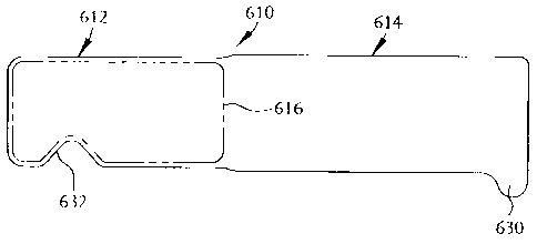
Figures 7, 8 and 9 illustrate further embodiments of a product label
constructed according to the present invention, identified respectively by
reference
numerals 410, ~ 10 and 610. It will be understood that labels 410, ~ 10 and
610 may be
CA 02385030 2002-03-22
WO 01/21395 PCT/US00/26335
constructed substantially similarly to any of the label embodiments disclosed
herein
including, but not limited to, labels 110, 2 ( 0 and 310 described above or
label 710
discussed below. Hence, only those structural aspects of labels 410, 510 and
610 which
materially depart From those previously addressed, or whose description may
otherwise
be necessary for a proper understandingof the invention, will be described in
detai'..
More particularly, labels 410, 510 and 610 depict exemplary, although
not limitative, means for facilitating separation of the releasable second
portions of the
labels from the first portions thereof when the labels are secured to objects
such as
products or product containers. These means may include a protrusion 430
provided
adjacent a distal end of the second portion 414 of label 410, a notch 532
adjacent an end
of the first portion 512 of label S 10, or a combination of a notch 630
adjacent a distal
end of second portion 614 and a notch 632 adjacent an end of the first portion
61 ? of
label 610. Each of these means enable easier insertion of a user's finger or
fingernail
beneath the releasable second portion of any of the labels herein described
when such
l 5 labels are affixed to a product or product container whereby the second
label portion
may be more easily lifted and separated from contact with the first label
portion.
Figures 10, 11 and 12 reveal a further presently preferred embodiment of
a product label 710 constructed in accordance with the present invention.
Label 710
may be manufactured in a substantially similar manner to and/or incorporate
any
combination of the features of previously described labels 110 through 610.
Hence,
only those features of label 710 not earlier mentioned will be discussed in
detail.
Label 710 preferably includes means 734 for evidencing tampering of
product prior to consumption thereof by an end user. According to a presently
preferred
construction, tamper evident means 734 comprise a fined or disposable tear
strip 736
12
CA 02385030 2002-03-22
WO 01/21395 PCT/US00/26335
contiguous with either the first, the first and second or , as shown, the
second portion
7 l4 of label 710 along perforation 738. Tear strip 736 may be of any length,
but
typically corresponds to the length of the circumference of C shown in Figure
12.
Figure 1 l shows label 710 as it would appear when affixed to the
circumferential side wall of a substantially cylindrical product container P.
To assure its
attachment to the product container prior to removal, all or a portion of the
tear strip 736
may be provided with a pressure sensitive or other suitable adhesive. When it
is desired
to access the contents of container P, the end user simply lifts a distal end
flap 740 of
the tear strip 736 and pulls the strip away from the remainder of the label
710 such that
the strip detaches from the label along perforation 738. Upon removal, the
tear strip
may then be discarded.
Once the tear strip 736 is removed, the pcoduct container cap or lid C is
exposed thereby enabling the user to remove the cap and access the contents of
the
product container P. Should the end user discover however that, prior to
purchase or
1 ~ use, that tear strip 736 is missing or damaged, tamper evident means 7~4
alerts the user
that consumption of the contents of product confainec P should be avoided.
Alternatively, distal end flap 740 may be omitted from tear strip 736.
Tear strip 736 may be' temporarily or permanently affixed to cap C and,
instead of the
end user tearing away tear strip 736, the end user may remove cap C by
twisting or
pulling thereby breaking perforation 738 and alerting a subsequent user that
the
container had been previously opened. In this embodiment, tear strip 736 may
either be
removed from or remain attached to cap C.
13
CA 02385030 2002-03-22
WO 01/21395 PCT/US00/26335
Referring now to Figure 18, there is shown preferredembodimentof a
product label l 800 constructed in accordance with the present invention. The
label
l 800 is essentially identical to the label shown in Figure 10. except that
the label I 800
is adapted to be applied to irregularly shaped objects, particularly tapered
objects. The
S label 1800 has a first portion 1812 with a top edge 1814 and a b~ttorr~ eage
1816. The
label 1800 also has a second portion 1817 with a top edge 1818 and a bottom
edge
1820. To accommodate application to a tapered object having a top with a
larger
circumference than the bottom, the top edges 1814 and 1820 are longer than the
corresponding bottom edges 1816 and 1818. In addition, the first portion 1812
may be
oriented at an oblique angle relative to the second portion 1817. The relative
length of
the top and bottom edges and the angle between the first and second portions
depend
upon the shape and size of the article to which the label is to be applied.
Generally, the
greater the taper of the article, the greater the angle and the greater the
difference
between the length of the top and bottom edges, and vice versa. The specific
lengths
and~angle are preferably selected so that the second portion 1817
substantially precisely
overlaps the first portion 1812 when the label 1800 is wrapped more than
360° around
an article. Alternatively, the specific lengths and angle may be selected so
that the
second portion 1817 only partially overlaps the first portion 1812 and
partially contacts
the container when the label 1800 is wrapped more than 360° around an
article. Some
or all of the edges may be curved to accommodate the difference in length
between the
top edges and the bottom edges. In Figure 18, the top edge 1820 of the second
portion
1817 is curved. In another alternative embodiment, the second portion may
comprise
one or more sub-sections, wherein each sub-section is at an angle relative to
the adjacent
preceding sub-section and said angle is selected to fit the Geometry of the
object to
2~ which the label is to be applied.
14
CA 02385030 2002-03-22
WO 01/21395 PCT/US00/26335
As mentioned above, the label of this invention may be comprised of a
tlexible and printable substrate such as paper or plastic (such as, for
example, polyvinyl
chloride, polyethylene or polypropylene)sheet or web material. Although each
label
may be made individually, labels are preferably produced in larger quantities
from rolls
of such substrate such as sheet stock which can be continuously printed,
coated with
adhesive, affixed to release paper, and cut to produce multiple labels. One or
more
areas or surfaces of the label may also be coated with a Lacquer or varnish in
order to
protect the label and/or printed inks from wear or other degradation. Also, as
an
alternative to the protective lacquer or varnish, an additional layer of
protective material
(e.g. a substantial transparent layer of plastic such as polyvinyl chloride,
polyethylene or
polypropylene) may be applied to select surfaces or areas of the label. The
means by
which the labels wilt be made will depend, in part, upon the features which
are to be
incorporated into such labels.
Referring to Figure l 3, there is shown a schematic depicting a method
I 5 for making the labels of this invention. It should be noted at the outset
that the order in
which the steps of the methods herein disclosed are carried out is not
necessarily critical
to successfully making the labels of this invention. As mentioned above, the
labels are
made from a flexible and printable substrate 800. Graphic or other inks 810
are printed
by printing step 820 (e.g. by tlexographic, rotogravure, silk screening or
other printing
methods) at predetermined locations on the top and/or bottom surfaces of
substrate 800.
For example, depending on the desired or necessary label configuration, inks
810 may
be applied to: the top surface of first label portion 112, 2 I2, 312, 412. ~
I2, 6I2, or 7I 2:
the top surface of second label portion 114, 214, 314a, 414. ~ 14. 614, or
7I4; and/or the
bottom surface of second label portion I 14, 214. 3 I4, 414, S I4. 614, or
714. Pressure
sensitive adhesive 830 is applied by step 840 (e.g. hot melt or other adhesive
means) to
1~
CA 02385030 2002-03-22
WO 01/21395 PCT/US00/26335
predetermined locations on the bottom surface of substrate 800 so as to
provide a means
by which the label may be affixed to the desired object. For example,
depending on the
desired or necessary label configuration, pressure sensitive adhesive 830 may
be applied
to the bottom surface of the first label portion 112, 212, 312, 412, 512, 612,
or 712.
Figure 14 depicts a method for making the labels of this invention which
adds to the steps shown in Figure 13 optional step 860 for applying tack or
releasable
adhesive 850 to select locations on substrate 800 such that the second label
portion may
be selectively and repeatedly adhered to the first label portion. For example,
depending
on the desired or necessary label configuration, tack or releasable adhesive
850 may be
applied to the distal edge of the bottom surface of first label portion 112
(i.e. I l8), 2 l ~-
312, 412, 512, 612, or 712.
Figure I ~ depicts a method for making the labels of this invention which
adds to the steps shown in Figure l 4 optional step 880 for applying a
protective material
870 to select locations over substrate 800 and/or inks 810 in order to protect
substrate
800 and/or inks 810 from wear or other degradation. For example, depending on
the
desired or necessary label confi;uration, protective dtaterial 870 (e.g.
lacquer, varnish,
PVC, or other substantially transparent protective material) may be applied to
any
surface. In addition, it should be noted that either adhesive 830 or 8~0 may
be applied
over protective material 870 provided that such application does not cause an
adverse
chemical reaction.
Figure I6 depicts a method for making the labels of this invention which
adds additional optional steps to the steps shown in Figure 1 ~. In this
embodiment,
substrate 800 is in the form of a web,irl order to facilitate the production
of larger
16
CA 02385030 2002-03-22
WO 01/21395 PCT/US00/26335
quantities of labels. Specifically, in step 900 substrate web 800 is fed
through a series
of process steps. Each such step is represented schematically by a box in
Figure 16.
As indicated above, the order in which the steps are carried out is not
necessarily critical to the successful manufacture of the labels of this
invention. With
this in mind, inks 810 are printed on one or both sides of web 800 in.
printing step 8?0.
Pressure sensitive adhesive 830 is applied to select areas of web 80U in
application step
840. Releasable adhesive 850 is applied to select areas of web 800 in
application step
860. A surface of web 800 bearing pressure sensitive adhesive 830 is applied
to release
paper 9 I 0 in application step 920 such that the resulting labels produced
from this
l0 process may later be removed for application to container P. Inapplication
step 880,
protective material 870 (e.g. lacquer, varnish (such as ultra violet varnish),
PVC, or
other substantially transparent protective material) is applied to select
surfaces of web
800 which surfaces generally do not contain pressure sensitive adhesive 830.
In die
cutting step 940, substrate web 800 (along with any protective material 870)
is die cut to
15 form label blanks, perforations, and/or other openings (if any) in web 800.
In stripping
step 960, substrate waste 9~0 is removed from release paper 910 after die
cutting step
940 thereby leaving finished label blanks releasably adhered to release paper
910 for
later application to container P. Finally, in optional rewinding step 980,
release paper
910 bearing die cut label blanks may be wound into rolls or other convenient
form for
20 later application of the resulting labels to.containerP or other objects by
manual or
automated means.
Figure 17 depicts another method for making the labels of this invention
which method is similar to the method set forth in Figure 16. except that
substrate web
800 is replaced with a pressure sensitive adhesive (PSA) material 80~. PSA
material
17
CA 02385030 2002-03-22
WO 01/21395 PCT/US00/26335
805 comprises substrate web 800 releasably adhered to release paper 910 by
pressure
sensitive adhesive 830 which adhesive 830 is typically coated on one side of
web 800.
In step 900 PSA material 805 is fed through a series of process steps. Each
such step is
represented schematically by a box in Figure 17. Again, the order in which the
steps of
this method are carried out is not necessarily-crit:~al to the successful
manufacture of
the labels of this invention. With this in mind, in step 990 release paper 910
is removed
From PSA material 805 to expose pressure sensitive adhesive 830.
As discussed above, in certain embodiments of the labels of this
invention, it is desirable to have certain portions of the label which are
coated with
( 0 pressure sensitive adhesive 830 (see e.g. portions 1 l6, 216 and 316 of
Figures 2 througfi
4 respectively and portions 416, 516, 6 l 6 and 716 of Figures 7 through ( 0
respectively)
in certain areas which are intended to be indicia or ink bearing surfaces (see
e.g. second
portions l l4, 2 l4 and 314 of Figures 2 through 4 respectively and 414, 5 (
4, 6 l4 and
714 of Figures 7 through 10 respectively). When PSA material 80~ is provided
with
1 ~ pressure sensitive adhesive 830 in areas where it is necessary or
desirable to print
indicia or inks 810, such areas must be "deadened" by either removing pressure
sensitive adhesive 830 from web 800 or by applying a detackifying material
such as a
varnish, laminate or other material capable of providing a suitable surface
for the
printing of indicia or inks 810. This deadening process is particularly useful
when it is
20 necessary or desirable to print on the surface of web 800 which surface
also bears
pressure sensitive adhesive 830 (see e.g. surface 118 of Figure ~).
The deadening process (if any is required) is carried out in step 1000.
With PSA material 80~ prepared, web 800 may be printed with inks 810 on any
surface
of the label which is suitable for accepting inks 810. Such printed surfaces
may include
is
CA 02385030 2002-03-22
WO 01/21395 PCT/US00/26335
both top and bottom surfaces of the label being produced, any surface not
bearing
pressure sensitive adhesive 830, or any surface which has been deadened in
step 1000.
Printing step 8 ( 0 may comprise one or more steps wherein the top and bottom
surfaces
of the label are printed either simultaneouslyor in separate steps. In one
embodiment of
the invention, inky 810 are printer o~i the top surface of the PSA material
80~, PSA
material 80~ is turned over, and inks 810 are printed on the bottom surface of
PSA
material 80~.
In step 920, release paper 910 is reapplied to web 800 with pressure
sensitive adhesive 830. Reapp(icationstep 920 may occur at any time after
printing step
8 ( 0 is completed with respect to the surface of the label which also bears
pressure
sensitive adhesive 830.
As in.the method depicted in Figure 16, application of protective
material 870 takes place in step 880, die cutting of individual labels takes
place in step
940, substrate waste 9~0 is stripped away in step 960, and the resulting web
which bears
I ~ the finished die cut label blanks is rewound in step 980.
Although the invention has been described in detail for the purpose of
illustration, it is to be understood that such detail is solely for that
purpose and that
variations can be made therein by those skilled in the art without departing
from the
spirit and scope of the invention.
19