Note: Descriptions are shown in the official language in which they were submitted.
CA 02385137 2002-05-07
- 1 -
SHEARING-STRIPPING MACHINE FOR ELECTRIC CABLES
The present invention relates to a shearing-stripping machine for electric
cables.
It is well known that for shearing electric cables into sections of different
length and stripping their ends and the possible wires constituting the
cables,
shearing-stripping machinEa are used, carrying out said operations starting
from cables of indefinite length wound as a coil.
The working method generally provides 'For unwinding the cable from the
coil and introducing it through suitable advancement devices into a shearing
and stripping unit where the cable is firstly shorn to the desired length and
then stripped at the ends.
When the cable comprises more wires, these wires may also be stripped
for a determined stretch so as to uncover the conductors.
The above mentioned shearing-stripping machines of known type
available on the market generally comprise one or more cable driving units
and one or more shearing and stripping units, the latter being provided with
opposite movable blades for shearing the cable and stripping its ends and
possibly also the ends of each wire of the cable.
The shearing-stripping machines carrying out also stripping of the wires,
in addition to the cable shearing and stripping unit, comprise also an
alignment
unit provided with opposite aligning jaws to place the wires juxtaposed to
each
other an an almost horizontal plane and opposite blades incising the sheaths
and carrying out stripping of the wires after their alignment.
In such machines of the prior art the aligning jaws and the stripping
blades are supported by suitable sliding units and are put in motion by
suitable
driving means moving them along a rectilinear direction generally orthogonal
to the cable advancement direction.
In the above mentioned machines of the prior art, the stripping blades for
the cable and the wires are juxtaposed on a generally vertical plane
perpendicular to the cable advancement direction. Both blades are put in the
working position by a first driving unit provided with an electric motor with
electronic motion control, while a second driving unit also provided with
electric motor with electronic motion control, move the blades in opposite
directions to carry out incision and stripping.
Such machines, therefore, have the drawback of having high
CA 02385137 2002-05-07
_ 2 _
construction costs in view of the presence of two driving units each provided
with a motor with electronic motion control and corresponding software.
Another drawback consists in that the presence of two motors involves
greater difficulty of regulation and greater need of maintenance together with
a
lower reliability of operation.
A further drawback arises from the fact that the wire aligning jaws are
independent from each other and each jaw is driven by a pneumatic actuator.
Indeed, the independent pneumatic control on the jaws does not warrant the
precise co-ordination of the movements of said jaws and consequently does
not warrant that the wires are always aligned ors the same generally
horizontal
plane. Consequently, during the wire stripping stage the blades could incise
besides the sheaths also the conductors so as to damage the conductors and
wear the blades.
The present invention aims at overcoming said drawback.
More particularly, a first object of the invention is to provide a shearing-
stripping machine wherein the means far driving and controlling the movement
of the stripping blades are of simpler construction in comparison of the known
types.
Another object of the invention is to provide a shearing-stripping machine
in which there is a unit for aligning the wires to be stripped having a self-
centering effect on the wires so as to place them always aligned and coplanar
during incision of the sheaths.
A further object of the invention is to provide a machine which is more
reliable and less expensive to be constructed in comparison with the machines
of the prior art.
Said objects are attained with a shearing-stripping machine for electric
cables that according to tine main claim comprises a casing on which the
following elements are mounted: driving means to advance said cable to be
shorn and stripped; at least a shearing and stripping unit comprising a blade
guide body provided with first blades supported by first blade holders for
shearing the cable, incising the sheath and stripping said cable and second
blades for incising the sheaths of the wires of the cable and stripping said
wires; at least an alignment unit of said wires adapted to place said wires
juxtaposed and coplanar before incision of said sheaths by said second
blades; first driving means for the movement of said first blades; second
CA 02385137 2002-05-07
- 3 -
driving means for the movement of said second blades; at least a
microprocessor unit controlling and actuating said driving means and said
driving units, characterized in that said first driving means comprise a
single
motor coupled to a mechanism to which adjustable stop means for the stroke
of said second blades are associated.
In this way with the same motor carrying out the movement of said first
shearing and stripping blades, the control of the movement of the second
stripping blades is obtained as well.
The motor is preferably an electric motor with electronic rotation control.
According to the preferred embodiment that will be described hereinafter,
the mechanism comprises ~~ screw coupled to the shaft of said single motor,
said screw having opposite right-hand and left-hand threads coupled with
corresponding screw nuts with which the adjustable stop means of the stroke
of the second stripping blades are associated, which consist of the same first
blade holders supporting the first shearing and stripping blades.
In this way the number of motors is advantageously reduced in
comparison with those used to make equivalent machines of the prior art, to
the advantage of a greater reliability of the machine and lower construction
costs.
The foregoing objects and advantages will be better understood by
reading the following description of a preferred embodiment of the invention
which is given as an illustrative but non limiting example with reference to
the
accompanying sheets of drawings in which:
FIG. 1 is a front view of the machine of the invention;
FIG. 2 is a top view of a part of the machine of the invention;
FIG. 3 is a view of part of the machine shown in FIG. 1;
FIG. 4 is an enlarged view of the sheari,~g and stripping blades of the
machine of the invention;
FIGS. 5 and 6 are two different views of the shearing and slipping blades
of FIG. 4 in the operative position;
FIG. 7 is a cross sectianal view of the machine of the invention, when
shearing the cable;
FIGS. 8 to 10 show the mutual positions of the blades of the machine
shown in FIG. 7;
FIG. 11 shows the machine of FIG. 3 in a different operative stage;
CA 02385137 2002-05-07
- 4 -
FIGS. 12 and 13 are different views of the shearing and stripping blades
of the machine of FIG. 11;
FIGS. 14 to 16 show different positions of the shearing and stripping
blades during the stage of incising the cable sheath;
FIG. 17 shows the machine of FIG. 11 during the cable stripping stage;
FIGS. 18 to 20 show the detail of the blades of the machine of FIG. 17
during the stripping operation;
FIGS. 21 and 22 show a detail of the machine of FIG. 17 in two different
operative stages;
FIG. 23 to 26 show details of the machine of FIG. 21 in the operative
stage;
F1G. 27 is another cross sectional view of the machine of FIG. 1;
FIG. 28 shows a detail of the machine of the invention during the incision
of the wire sheaths;
FIGS. 29 and 30 are two different views of the blades during incision of
the sheaths of the cable wires;
FIG. 31 is a detail of the machine of FIG. 22 during the wire stripping
stage;
FIG. 32 shows the detail of the blades of the machine of FIG. 31 during
stripping of the cable wires;
FIG. 33 shows the machine of FIG. 17 during another working stage;
FIGS. 34 and 35 show details of the shear ing and stripping blades of the
machine of F1G. 33;
FIG. 36 is an enlarged view of the incision stage of the cable sheath;
FIGS. 37 is an enlarged view of the cable stripping stage;
FIG. 38 shows the wire aligning phase;
FIG. 39 shows the aligned wires;
FIG. 40 shows incision of the wire covering sheaths;
FIG. 41 shows the wire stripping;
FIGS. 42 and 43 are two different views of the outlet cable guide;
FIGS. 44 to 46 are different views of the wire stripping blades; and
FIG. 47 is a detail of FIG. 44.
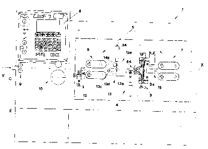
The shearing-stripping machine subject of the present invention is
generally shown in FIG. 1 and partially also in FIG. 2 where it is generally
indicated with reference numeral 1.
CA 02385137 2002-05-07
- 5 -
One can see that the machine comprises a casing 2 on which the
following elements are mounted: driving means generally indicated with
numeral 5 adapted to advance cable C along a longitudinal direction X in the
way indicated by arrow V; a unit generally indicated with numeral 3 for
shearing the cable C and stripping both the cable C and the wires F
constituting the cable; an alignment unit for the wires F generally indicated
with numeral 4 and arranged upstream the shearing and stripping unit 3 to
arrange the wires aligned on a generally horizontal plane one aside the other
before the stripping operation; a microprocessor unit generally indicated with
numeral 8 controlling and actuating the advancement, shearing and stripping
operations.
More particularly, the driving means 5 comprise a first driving unit
generally indicated with numeral 6 advancing the cable C to the alignment unit
4; and a second driving unit generally indicated with numeral 7 moving the
cable C away from the shearing and stripping unit.
The shearing-stripping machine comprises also a cable guiding roller
inlet 9 followed by a gauging unit 10 arranged upstream the first driving unit
6.
Downstream the gauging unit 10 and just upstream the first driving unit 6
there is an inlet cable guide 12 while immediately downstream the first
driving
unit 6 there is an intermediate cable guide 13.
The intermediate cables guide 13 comprises a tubular member 13a having
an end 13b pivoted through a pin 13c to the movable member 13d of a first
actuator 13 fixed to the machine casing 2.
A second actuator 14 also fixed to the casing 2 of the machine, has the
movable member 14a connected in an intermediate position to the tubular
member 13a.
Therefore, the tubular member 13a through the actuators 13 and 14 may
be translated horizontally and also rotated on the pin 13c.
An outlet cable guide 15 is arranged between the shearing and stripping
unit 3 and the second driving unit 7.
With regard now to the shearing and stripping unit 3 that can be seen in
greater detail also in FIGS. 3, 7, 11 and 17, one can see that it comprises a
blade guiding body 3a provided with two first blades 18, 19 for shearing the
cable C and incising the outer sheath C1 covering the cable, as shown more
particularly in FIGS. 4 to 6, 8 to 10, 12 to 18 and 18 to 20, and two second
CA 02385137 2002-05-07
- 6 -
blades 42, 43 more particularly the sheaths F1 covering the wires F
constituting the cable C.
With reference more particularly to FIGS. 4 and 5, the first blades 18, 19
consist of a couple of plates 20, 21 with planar surfaces 20a, 21a closely
juxtaposed one to the other', each plate being provided with a cutting element
22, 23 defined by the sharp edge 24, 25. The cable C to be shorn and stripped
is arranged between the sharp edges 22, 23 of said blades properly spaced
from each other.
Each of said first blades 18, 19 is supported by the first blade holder 32,
33 respectively to be seen more particularly in FIG. 7, each blade holder
being
in term coupled to first driving means generally indicated with 34 for moving
the blades 18, 19.
According to the invention said first driving means 34 comprise a single
motor 35 whose driving shaft 36 is connected to a mechanism generally
indicated with numeral 34a to which adjustable stop means 80, 81 of the
stroke of the second blades 42, 43 are associated.
Preferably, said single motor 35 is an electric motor with electronic
rotation control. As shown in FIG. 7 the mechanism 34a comprises a screw 37
coupled to the shaft 36 of the electric motor 35 and provided with opposite
right-hand thread 37b and left-hand thread 3'a coupled with corresponding
screw nuts 38, 39 to which adjustable stop means 80, 81 of the stroke of the
second blades 42, 43 are associated.
Therefore, the blades 18, 19 can move along the directions indicated by
axis Ya, Yb in the opposite ways indicated by arrows 40a, 40b according to
the rotation direction of motor 35.
The adjustable means stop means 80, 81 of the stroke of the second
blades 42, 43 are constituted by the same first blade holders 32, 33, each of
them acting as a stop element for a corresponding shaped head 42b, 43b,
belonging to each second blade 42, 43 to be seen in FIGS. 45 to 47 as will be
described in more detail hereinafter.
The second blades 42, 43 can be seen in detail in FIGS. 17, 21, 22, 28
and 31 and still in grater detail in FIGS. 45 to :.f8 where one can see that
the
blades consist of a couple of plates 44, 45 vertically aligned to each other
and
provided with opposite rectilinear cutting edges 42a, 43a for incising the
sheaths F1 covering each wire F.
CA 02385137 2002-05-07
_ 7 _
At the opposite part relative to the cutting edge, each second blade has
the above mentioned shaped head 42b, 43b with a hole 42c, 43c for
connection to second driving means 52 shown in FIG. 21 adapted to move the
blade in the same vertical direction of the first blades 18, 19 along the
opposite
ways indicated by arrows 40a or 40b.
Said second driving means 52 consist of a couple of fluidic actuators
52a, 52b supported by the blade guiding body 3a and having the rods 52c,
52d each connected to a corresponding shaped head 42b, 43b of a second
blade 42, 43.
With regard now to the alignment unit 4 for the wires F constituting the
cable C, said unit is arranged upstream the shearing and stripping unit 3 as
shown in FIG. 21 and is provided with an aligning chuck 54 to place the wires
F coplanar and juxtaposed to each other before incising their sheaths.
The aligning chuck cornprises two aligning jaws 55a, 55b, each jaw being
supported by a rotation pin 59, 60 supported by the machine casing 2.
A pinion gear 61, 62 is associated to each of said rotation pins 59, 60
and one of said pins, far instance the lower rotation pin 60 is in its turn
associated to third driving means through a connecting rod 63.
Said third driving means consist of a fluidic actuator 58 of commercial
type available on the market, whose rod 58a has the end 58b pivoted to the
connecting rod 63 for connection to the lower pin 60.
Movement of the rod 58a gives to the jaws 55a, 55b of the aligning chuck
54 opposite rotation movements around the corresponding pins 59, 60
because the pinion gears 61, 62 are mutually engaged and therefore the
rotation given by the actuator 58 to the lower pins 60 is transmitted also to
the
upper pin 61.
Preferably but not necessarily the aligning jaws 55a, 55b as shown in
FIGS. 23 and 24 comprise shaped blades 55c, 55d having opposite planar
surfaces 55e, 55f in contact with the wires F constituting the cable C.
The jaws 55a, 55b, as shown more particularly in FIGS. 24 and 26, have
the function to align the wires F juxtaposing them to each other on the same
plane, before incising their sheaths F1 to the second blades 42, 43.
In this way a perfect incision of the sheaths by the second blades 42, 43
is warranted and the risk that the blades incise also the metal wire because
of
a misalignment of the wires F is prevented.
CA 02385137 2002-05-07
As to the position of the second blades 42, 43 and more particularly,
penetration of their cutting Edges 42a, 43a into the sheaths F1 of the wires
F,
such penetration is set through adjustable stop means generally indicated with
80, 81 and to be seen particularly in FIGS. 27 and 28, consisting of each
first
blade holder 33, 32 acting as stop for the carresponding shaped head 42b,
43b of a corresponding second blade 42, 43.
In such a way control .of penetration of the cutting edges 42a, 43a of the
second blades 42, 43 into the sheaths F1 occurs using the same first blade
holder 33, 32 of the first blades 18, 19 and also the same electric motor 35
carrying out movement of the first blade holders 33, 32.
Indeed, the microprocessor unit 8 controlling rotation of the motor 34
allows to vary the vertical stroke of the second blades 42, 43 changing the
position of the first blade holders 33, 32 and therefore the point of contact
with
the shaped heads 42b, 43b and consequently, the penetration of the second
blades 42, 43 into the sheaths F1 to be incised according to their thickness.
Finally, as to the outlet cable guide 15 shown in greater detail in FIGS. 43
and 44 illustrating its closed and open position respectively, it consist of
an
actuator 15a fixed through a connection flange 15b to the machine casing and
controlling opening and closing of a gripping chuck generally indicated with
90
and consisting of a couple of jaws, 91, 92 with opposite shaped ends 93, 94.
These ends when arranged in the closed position shown in FIG. 43, define a
hole 95 accomodating the cable C.
In operation the cable C to be shorn to size and stripped, is introduced at
the cable guiding roller inlet 9 and is advanced along the direction indicated
by
arrow V by the driving units 6 and 7.
The gauging unit 10 detects the length of cable C set in the controlling
and actuating microprocessor unit 8 and stops its advancement when reaching
the desired shearing length.
This occurs when along the advancement direction V the desired length
of cable is protruding from the shearing and stripping unit 3.
In such a position as shown also in FIGS. 5 and 6, the cable C is
arranged between the first shearing and stripping blades 18, 19 ready to
undergo the shearing operation when the control and actuation unit 8 on the
basis of a set program, actuates the motor 35. Said motor 35 moves the
blades 18, 19 according to the opposite directions indicated by arrows 70, 71
CA 02385137 2002-05-07
_ g _
in FIG. 9, bringing the cutting edges 22, 23 close to the cable along the
movement axis Y until it is shorn.
At this point the intermediate cable guide 13 is lifted as shown in FIG. 17
while the first blades 18, 19, as shown in FIGS. 12 and 13, invert their
mutual
movement to return to the configuration in which they allow passage of cable
C between them.
The cable C is then retracted in the direction indicated by arrow V1 in
FIG. 11 for a stretch equal i:o the stripping length so as to place the cable
end
under the shearing and stripping unit 3 to carry out incision of the sheaths
covering said cable.
The blades 18, 19 are then moved along the opposite directions
indicated by arrows 70, 71 until they are arranged in the position shown in
F1GS. 14 to 16 where the sharp edges 24, 25 of the cutting rims 22, 23 of both
blades penetrate into the sheath C1 for an amount sufficient to incise
circumferentially at least for a portion.
The microprocessor unit controls rotation of the motor 35 that through the
coupling of screw 37 and corresponding screw 36, 39 causes the blades 18,
19 to move for a controlled amount so as to regulate also the depth of
penetration of the blades into the sheath as a function of its thickness.
After the sheath incision, the second driving unit ? inverts movement of
cable C causing it to advance again in the direction indicated by arrow V, so
as to obtain separation of the sheath C1 by contrast against the first blades
18, 19 as shown more particularly in FIG. 18, 19 and 20.
To proceed to stripping the wires F, the second driving unit 7, as shown
in FIG. 21, inverts again the rotation of the belts 7a, 7b so that the cable C
is
again retracted along the direction indicated by arrow V1 to place the wires F
under the second cutting blades 42, 43 and the aligning jaws 54, 55 as shown
in FIG. 21.
At this point a control imparted by the control and actuation unit 8 causes
the aligning chuck 54 to close whose jaws 55a, 55b are arranged against the
wires F in the position shown in FIG. 22.
If the wires F are arranged in the superimposed position shown in FIG.
24, by acting on the second driving unit 7, the cable C is again advanced
along the direction indicated by arrow V in FIGS. 25 and 26 and pressure of
the jaws 55a, 55b causes the wires F to be arranged on a single plane as
CA 02385137 2002-05-07
- 10 -
shown in FIG. 26.
The self-centering effect of the opposite rotation motion of the aligning
jaws 55a, 55b constituting the aligning chuck 54, warrants alignment of the
wires F always on the same plane.
At this point by actuating the actuators 52a, 52b, the second blades, 42,
43 incise the sheaths F1 as shown in FIGS. 28, 29 and 30 and their
penetration into the sheaths F1 is regulated by the position of the contact
elements of the shaped heads 42b, 43b of the second blades 42, 43 with the
first blade holders 32, 33 imposed by the motor 35.
By inverting again the advancement of the cable C along the direction of
arrow V, separation of the sheaths F1 of wires F by contrast against the
second blades 42, 43 is obtained as shown also in the detail of FIG. 32.
In this way the conductors M constituting each wire F of the cable C are
uncovered.
In order to proceed to strip the end of the cable C kept inside the
intermediate cable guide 13, the cable guide is arranged aligned along axis X
as shown in FIG. 33 and through the driving unit 6 the cable C is advanced
until the end to be shorn is places under the action of the sharing and
stripping
unit 3. Proceeding exactly according to the same previously described
sequence and starting from the configuration shown in FIGS. 34 and 35,
through the movement of the first blades 18, 19 incision of the sheaths C1 of
cable C is carried out as shown in FIG. 35, followed by its stripping with
separation of the sheath C1 a shown in FIG. 37.
In order to strip the wires F one proceeds in the previously described
way, firstly aligning the wires as shown in the details of FIGS. 39 and 42,
then
incising their sheaths as shown in FIG. 40 and then stripping them as shown in
FIG. 41.
The stretch of stripped cable is then discharged by movement in the
direction of the arrow V givE:n by the second driving unit 7, or by opening
the
gripping chuck 90.
In view of the foregoing one can understand that the described machine
carries out the method of shearing and stripping electric cables and attains
all
the previously mentioned objects.
It is clear that in the executive stag:: many modification could be made to
the method and the shearing stripping machine carrying out said method, that
CA 02385137 2002-05-07
- 11 -
should be considered all covered by the present invention when falling within
the scope of the appended claims.