Language selection

Search

Patent 2385188 Summary

Third-party information liability

Some of the information on this Web page has been provided by external sources. The Government of Canada is not responsible for the accuracy, reliability or currency of the information supplied by external sources. Users wishing to rely upon this information should consult directly with the source of the information. Content provided by external sources is not subject to official languages, privacy and accessibility requirements.

Claims and Abstract availability

Any discrepancies in the text and image of the Claims and Abstract are due to differing posting times. Text of the Claims and Abstract are posted:

  • At the time the application is open to public inspection;
  • At the time of issue of the patent (grant).
(12) Patent: (11) CA 2385188
(54) English Title: SEGMENTED TIRE MOLD
(54) French Title: MOULE A PNEUMATIQUES SEGMENTE
Status: Expired and beyond the Period of Reversal
Bibliographic Data
(51) International Patent Classification (IPC):
  • B29C 33/48 (2006.01)
  • B29C 33/22 (2006.01)
  • B29D 30/06 (2006.01)
(72) Inventors :
  • LONEY, GREGORY LEE (United States of America)
  • ROBEK, DAVID CHESTER (United States of America)
(73) Owners :
  • THE GOODYEAR TIRE & RUBBER COMPANY
(71) Applicants :
  • THE GOODYEAR TIRE & RUBBER COMPANY (United States of America)
(74) Agent: MARKS & CLERK
(74) Associate agent:
(45) Issued: 2008-12-09
(86) PCT Filing Date: 1999-10-01
(87) Open to Public Inspection: 2001-04-12
Examination requested: 2004-05-20
Availability of licence: N/A
Dedicated to the Public: N/A
(25) Language of filing: English

Patent Cooperation Treaty (PCT): Yes
(86) PCT Filing Number: PCT/US1999/022799
(87) International Publication Number: WO 2001024987
(85) National Entry: 2002-03-18

(30) Application Priority Data: None

Abstracts

English Abstract


A segmented tire mold having radially movable circumferentially spaced sliding
center segments activated by sliding
connections between an upper mold half and the segments in response to opening
and closing of the mold.


French Abstract

L'invention concerne un moule à pneumatiques segmenté, comportant des segments centraux coulissants espacés sur la circonférence et radialement mobiles, que l'on active par des connexions coulissantes entre une moitié de moule supérieure et les segments, en réponse à l'ouverture et à la fermeture du moule.

Claims

Note: Claims are shown in the official language in which they were submitted.

The embodiments of the invention, in which an exclusive property or privilege
is claimed, are defined as follows:
1. A segmented tire mold having an upper mold half, a lower mold half and
radially movable circumferentially spaced sliding segments, characterized by:
a. each of said sliding segments being mounted on said lower mold half for
radial movement; and,
b. a disengagable sliding connection between said upper mold half and each
of said sliding segments for moving said segments radially of said mold
between an
open retracted position and a closed molding position, said disengagable
connection
comprising a plurality of spaced bars mounted on said upper mold half and
engagable
with a slot in each of said segments.
2. A segmented tire mold in accordance with claim 1 further characterized by a
spring being mounted in said lower mold half and in engagement with each of
said
sliding segments for holding said segments in said open retracted position.
3. A segmented tire mold having an upper mold half, a lower mold half and
radially movable circumferentially spaced sliding segments characterized by:
a. each of said sliding segments being mounted on said lower mold half for
radial movement; and,
b. a disengagable sliding connection between said upper mold half and each
of said sliding segments for moving said segments radially of said mold
between an
open retracted position and a closed molding position, said disengagable
connection
comprising a bar mounted on said upper mold half in sliding engagement with a
slot
in each of said sliding segments.
4. A segmented tire mold in accordance with claim 3 further characterized by
said
bar having rollers for engagement with surfaces of said slot for reducing the
sliding
resistance of said sliding connection.
5. A segmented tire mold in accordance with claim 1 further characterized by
said lower mold half having circumferentially spaced centering pins extending
upwardly for register in corresponding spaced-apart holes in said upper mold
half.

6
6. A segmented tire mold in accordance with claim 1 further characterized by
stop members mounted on said lower mold half radially outward of said sliding
segments for limiting radial movement upon opening of said mold.

Description

Note: Descriptions are shown in the official language in which they were submitted.


CA 02385188 2002-03-18
WO 01/24987 PCT/US99/22799
1
SEGMENTED TIRE MOLD
Technical Field
This invention relates to segmented tire molds and especially to molds having
center
segments which are movable radially in response to opening and closing of the
mold.
Background of the Invention
Full segmented molds such as the mold shown and described in U.S. Patent No.
5,585,064 provide for expanding and contracting segments, however, the
segments are mounted
on the top mold and must be lifted to retract the segments. In addition to the
added power
required to lift the segments, the wear on the parts is also a disadvantage of
this type of mold.
Other segmented molds, such as the mold shown in Great Britain Patent GB
1,176,162
provide hinged segments with springs for retracting the hinge pins of the
segment. The tilt type
segmented molds of this type do not provide for loading an uncured tire
without engaging the
bridge work on the segments. This is especially objectional for molds with
curved segmental
boundary designs where the mold segments must be retracted in a direction
perpendicular to the
vertical axis of the segments.
Summary of the Invention
The present invention is directed to a segmented mold having radially movable
center
segments which are mounted on the lower mold half. Each center segment has a
slotted
connection with a sloped surface of the upper mold half for retracting and
then returning the
segment to the registered position for molding a tire. The slot in the center
segment is open at
the top to permit opening of the mold without lifting of the segment. A spring
holds the center
segment in a radially outward position against a stop in the lower mold half
which positions the
slot for engagement with the upper mold half upon closing of the mold.
In accordance with one aspect of the invention there is provided a segmented
tire mold
having an upper mold half, a lower mold half and radially movable
circumferentially spaced
sliding segments characterized by:
a. each of the sliding segments being mounted on the lower mold half for
radial
movement,
b. a disengagable sliding connection between the upper mold half and each of
the
sliding segments for moving the segments radially of the mold between an open
retracted position
and a closed molding position.
In accordance with another aspect of the invention there is provided a method
of
vulcanizing a tire in a segmented tire mold having an upper mold half, a lower
mold half and

CA 02385188 2002-03-18
WO 01/24987 PCT/US99/22799
2
radially movable circumferentially spaced center segments in sliding
engagement with the lower
mold half and slidably engagable with the upper mold half upon closing of the
mold characterized
by:
a. opening the mold by lifting the upper mold half away from and out of
sliding
engagement with the center segments,
b. moving the center segments radially outward by the sliding engagement with
the
upper mold half,
c. limiting the movement of the center segments radially outward by stop means
on
the lower mold half,
d. placing an unvulcanized tire on the lower mold half,
e. lowering the upper mold half in sliding engagement with the center segments
for
moving the center segments radially inwards into engagement with the tire upon
closing of the
mold,
f. applying heat to the tire mold to vulcanize the tire,
g. lifting the upper mold half for sliding the center segments radially
outward on the
lower mold half, and
h. removing the tire from the tire mold.
Brief Description of Drawings
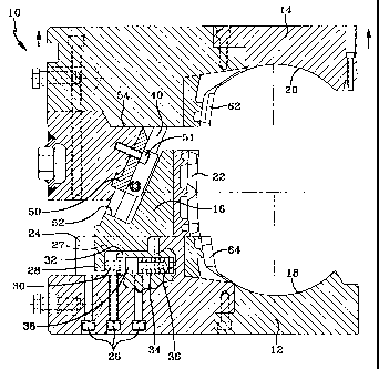
Fig. 1 is a plan view of the lower mold half and the center segments embodying
the
invention.
Fig. 2 is a section of the mold embodying the invention taken along line 2-2
in Fig. 1 with
parts being broken away to show the plunger and coil springs of the mold in
the closed position.
Fig. 3 is a section like Fig. 2 showing the center segment in a partially
retracted position.
Fig. 4 is a enlarged fragmentary sectional view of one of the centering pin
connections
between the lower mold half and the upper mold half taken along the plane of
line 4-4 in Fig. 2.
Fig. 5 is an enlarged fragmentary sectional view of the lower mold half taken
along the
line 5-5 in Fig. 1 showing the stop means and spring pin for a center segment
in the fully
retracted position.
Fig. 6 is an enlarged fragmentary sectional view of the sliding connection
between the
upper mold half and one of the center segments taken along line 6-6 in Fig. 2.
Detailed Description of the Invention

CA 02385188 2007-04-20
3
Referring to Figs. 1 and 2, a segmental tire mold 10 is shown having a lower
mold half 12, an upper mold half 14 and radially movable center segments 16.
The
lower mold half 12 and the upper mold half 14 have sidewall forming surfaces
18 and
20 respectively. In addition to the lower mold half 12, upper mold half 14 and
center
segments 16, the segmental tire mold 10 also includes means for heating the
molds
and lifting and lowering the upper mold half 14. The center segment 16 has
tread
forming surfaces 22, which are movable radially for disengaging the mold 10
from the
tire after vulcanization.
Each of the center segments 16 is slidably mounted on a T-bar 24, fastened to
the lower mold half 12 by bolts 26 or other suitable means. Each T-bar 24
extends
radially of the mol d 10 and slides in a slot 27 extending radially of the
mold.
Each of the center segments 16 also has recesses with end flanges 28 for
plungers 30 mounted in sleeves 32 mounted on the lower mold half 12 and urged
radially outward by coil springs 34 located between the recessed surface 36 in
the
lower mold half 12 and a flange 38 on the plunger 30. The coil springs 34 hold
the
center segments 16 in the fully retracted position after mold half 12 is
pulled away
from the center segments 16.
Referring to Figs. 2 and 6, a slot 40 is provided in a sloped surface 42 of
the
center segment 16 and has grooves 44 for receiving rollers 46 mounted on a
shaft 48,
supported by a bar member 50 which is bolted to the upper mold half 14 by a
bolt 51.
The slot 40 extends from a base surface 52 to a top edge 54 of the center
segment 16.
With this construction, lifting of the upper mold half 14 from the position
shown in
Fig. 2 to the position shown in Fig. 3 provides for travel of the rollers 46
upward
through the grooves 44 pulling the center segments 16 radially outward to the
position
shown in Fig. 3.
Referring to Fig. 5, stop means, such as bolts 56 are located on the lower
mold
half 12 at spaced apart positions for limiting the radially outward movement
of the
center segments 16 beyond the partially open position shown in Fig. 3 to a
position
where the upper mold half 14 is lifted away from the lower mold half 12 and
center
segment 16 removing the rollers 46 from the grooves 44. The bolts 56 hold the
center
segments 16 in the position shown in Fig. 5 by springs 36 so that when the
upper
mold half 14 is lowered onto the center segment 16, the rollers 46 will be in
alignment
with and enter the grooves 40 for closing the mold 10.

CA 02385188 2007-04-20
4
Referring to Fig. 4, centering pins 58 are mounted in the lower mold half 12
at
circumferentially spaced positions for registering in holes 60 in the upper
mold half
14 when the upper mold is lowered into position over the center segment 16 and
lower mold half 12.
The upper mold half 14 has shoulder forming surfaces 62 adjacent the sidewall
forming surfaces 20 and the lower mold half 12 has shoulder forming surfaces
64
adjacent the sidewall forming surfaces 18. Positioned between the shoulder
forming
surfaces 62 and 64 are the tread forming surfaces 22 on the center segments
16.
In addition to the lower mold half 12, upper mold half 14 and center segments
16, the segmental tire mold 10 also includes means for heating the molds and
lifting
and lowering the upper mold half 14. These services are well known in the art
and are
included in this disclosure, although not shown in the drawings or described
herein.
In operation the segmental tire mold 10 is opened by lifting the upper mold
half 14 away from the center segments 16 and lower mold half 12 causing the
center
segments 16 to retract to a partially open position shown in Fig. 3. The
springs 36
move the segments 16 to the fully open position shown in Fig. 5. A green
unvulcanized tire is then lowered into the lower mold half 12 and the upper
mold half
14 lowered so that the centering pins 58 shown in Fig. 4 are registered in the
centering
pin holes 60. The grooves 44 in the center segments are then in position for
receiving
the rollers 46 of the segment bars 50 in the slots 40 of the center segments
16. Further
lowering of the upper mold half 14 from the position shown in Fig. 3 to the
position
shown in Fig. 2 causes the tread forming surfaces 22 of the center segments 16
to
move radially inward into the position shown in Fig. 2. During the closing of
the
mold 10, the springs 34 are compressed by movement of the flange 28 radially
inward
against the plungers 30. The segmental tire mold 10 is then in position for
molding
the tire upon the application of heat for a predetermined period of time.
After the tire is vulcanized, the mold 10 is opened by raising the upper mold
half 14. This results in radially outward movement of the center segments 16
due to
the action of each T-bar 24 in each slot 27 of each center segment. As the
upper mold
half 14 is lifted, the rollers 46 attached to the upper mold half engage the
surfaces of
the slot 40 in the center segments 16 urging them radially outward out of
engagement
with the cured tire tread. The upper mold half 14 may then be lifted away from
the
center segment 16 and lower mold half 12 for removal of the tire.

Representative Drawing
A single figure which represents the drawing illustrating the invention.
Administrative Status

2024-08-01:As part of the Next Generation Patents (NGP) transition, the Canadian Patents Database (CPD) now contains a more detailed Event History, which replicates the Event Log of our new back-office solution.

Please note that "Inactive:" events refers to events no longer in use in our new back-office solution.

For a clearer understanding of the status of the application/patent presented on this page, the site Disclaimer , as well as the definitions for Patent , Event History , Maintenance Fee  and Payment History  should be consulted.

Event History

Description Date
Time Limit for Reversal Expired 2010-10-01
Letter Sent 2009-10-01
Grant by Issuance 2008-12-09
Inactive: Cover page published 2008-12-08
Inactive: Final fee received 2008-07-25
Pre-grant 2008-07-25
Notice of Allowance is Issued 2008-02-04
Letter Sent 2008-02-04
Notice of Allowance is Issued 2008-02-04
Inactive: Approved for allowance (AFA) 2007-10-26
Amendment Received - Voluntary Amendment 2007-04-20
Inactive: S.30(2) Rules - Examiner requisition 2006-10-30
Inactive: IPC from MCD 2006-03-12
Letter Sent 2004-06-02
Request for Examination Requirements Determined Compliant 2004-05-20
All Requirements for Examination Determined Compliant 2004-05-20
Request for Examination Received 2004-05-20
Inactive: Cover page published 2002-09-11
Inactive: Notice - National entry - No RFE 2002-09-06
Letter Sent 2002-09-06
Application Received - PCT 2002-06-17
National Entry Requirements Determined Compliant 2002-03-18
Application Published (Open to Public Inspection) 2001-04-12

Abandonment History

There is no abandonment history.

Maintenance Fee

The last payment was received on 2008-09-19

Note : If the full payment has not been received on or before the date indicated, a further fee may be required which may be one of the following

  • the reinstatement fee;
  • the late payment fee; or
  • additional fee to reverse deemed expiry.

Please refer to the CIPO Patent Fees web page to see all current fee amounts.

Owners on Record

Note: Records showing the ownership history in alphabetical order.

Current Owners on Record
THE GOODYEAR TIRE & RUBBER COMPANY
Past Owners on Record
DAVID CHESTER ROBEK
GREGORY LEE LONEY
Past Owners that do not appear in the "Owners on Record" listing will appear in other documentation within the application.
Documents

To view selected files, please enter reCAPTCHA code :


To view images, click a link in the Document Description column. To download the documents, select one or more checkboxes in the first column and then click the "Download Selected in PDF format (Zip Archive)" or the "Download Selected as Single PDF" button.

List of published and non-published patent-specific documents on the CPD .

If you have any difficulty accessing content, you can call the Client Service Centre at 1-866-997-1936 or send them an e-mail at CIPO Client Service Centre.


Document
Description 
Date
(yyyy-mm-dd) 
Number of pages   Size of Image (KB) 
Representative drawing 2002-09-11 1 30
Cover Page 2002-09-11 1 54
Claims 2002-03-18 2 75
Abstract 2002-03-18 1 71
Drawings 2002-03-18 4 152
Description 2002-03-18 4 218
Description 2007-04-20 4 224
Claims 2007-04-20 2 56
Representative drawing 2008-11-21 1 29
Cover Page 2008-11-21 1 55
Notice of National Entry 2002-09-06 1 192
Courtesy - Certificate of registration (related document(s)) 2002-09-06 1 112
Acknowledgement of Request for Examination 2004-06-02 1 176
Commissioner's Notice - Application Found Allowable 2008-02-04 1 164
Maintenance Fee Notice 2009-11-12 1 170
PCT 2002-03-18 14 587
Correspondence 2008-07-25 1 57