Note: Descriptions are shown in the official language in which they were submitted.
CA 02385367 2002-05-07
FIELD OF THE INVENTION:
This Invention relates to a system for indicating the velocity of an object.
More
particularly, this Invention relate:. to a sysrtem that determines information
which can be
used to calculate or infer the velocity of an object by measuring the force at
the point of
impact with a sensor that is attached to a can-ier.
DESCRIPTION OF RBLATEL) ART:
The prior art relevant to this Invention, and described below, consists of
various systems
and devices for measuring the velocity of an object, the distance traveled by
an object or
the location of the point of impact of an object on an implement. It is thus
known ir~ the
art that the velocity of an object may be measured or inferred by using
sensors and that
the measurement or the inferred velocity may be displayed on a display.
United States Patent No. 4,088,324 to E. W. Farmer, filed December 6, 1976, is
a device
for measuring the impact between an implement and a stmck object and for
displaying
the distance traveled by the object. The device is comprised of motion
sensors, a signal
circuit, an environmental correction circuit and a display. The Farmer patent
suffers from
the fact that it requires a motion sensor that is responsive to the distance
traveled by the
object.
United States Patent No. 4,801,880 to K. Eishi, filed November 28, 1986, is a
device for
measuring the speed of a moving object. The device is comprised of movement
start and
finish detecting means, a time measuring means, a speed computing means and a
display
unit. The Eishi patent suffers from the fact: that it requires a movement
detection and time
v
1
CA 02385367 2002-05-07
measuring means.
United States Patent No. 4,898,389 to D. J. Platt, filed September 8, 1987, is
a device for
golf training. The device is comprised of a golf club with an impact sensitive
transducer
which generates an electrical signal and has an electrical signal receiver to
determine the
location of the point of impact of the object on the club face. The Platt
patent suffers from
the fact that it requires electrical. signals to determine the location of the
point of impact
between the club-face and the stmck object.
United States Patent No. 5,419,65 to T. J. Gordon et al, filed August 20,
1993, is an
electrical device for detecting th.e location and speed or force of impact
with- a target. The
device is comprised of a projectile target with an elastomeric enclosure and a
matrix. The
Gordon patent suffers from the fact that it requires measurement of the impact
of an
object on a stationary matrix target.
United States Patent No. 5,688,183 to J. Sabatino, filed March 21, 1995, is a
velocity
monitoring system for golf clubs. The system is comprised of a golf club, a
monitor, and
an acceleration sensor that generates a noise reading. The Sabatino patent
suffers from the
fact that it requires a noise reading to calculate club speed.
Canadian Patent No. 2,146,527 to M. Tison et al, filed April 6, 1995, and laid
open on
October 7, 1996, is an apparatus for measuring the speed of a hockey puck. The
apparatus
is comprised of a simulative puck, a guide track and a computer system. The
Tison patent
suffers from the fact that it requires a guide track and special puck.
United States Patent No. 5,806,048 to B. D. Edward, filed July 23, 1996, is an
apparatus
for determining the speed of a projectile. The apparatus is comprised of a
control logic
unit with a pulsating clock and an acoustic sensor. The Edward patent suffers
from the
fact that it requires an acoustic sensor and a timer.
United States Patent No. 6,212,129 to M. Nussbaumer, PCT filed September 19,
1997, is
2
CA 02385367 2002-05-07
a device for measuring the velocity of a variety of objects. 'The device is
comprised of a
base unit with a sound wave emitter, a sound wave receiver, a computing unit
and a
display screen. The device is placed next to the projected line of movement of
the object.
The Nussbaumer patent suffers from the fact that it requires a sound wave
emitter and
receiver, and Doppler effects to measure projectile speed.
Canadian Patent No. 2,248,114 to A. E. Dilz, filed November 24, 1997, and laid
open on
August 6, 1998, is a miniature sports radar speed measuring device. The device
is
comprised of a radar in the form of a microwave radio frequency transmitter
and a
receiver. The Dilz patent suffers frc,~m the fact that it requires a radio
transceiver and
Doppler effects to measure speed.
United States Patent No. 6,173,610 to R. L. Pace, filed December 23, 1998, is
a sports
swing impact speed indicator. The device is comprised of an accelerometer, an
event
window timer and a LCD. The Pace patent suffers from the fact that it requires
a timer
and a sensor to measure speed.
PCT Patent No. WO 01/00285 to Y. C. Pao, filed June 24, 1999, is a method and
apparatus for a portable golf training system with an optical sensor net. The
device is
comprised of an optical sensor net system that utilizes light emitters. The
Pao patent
suffers from the fact that it requires an optical net, sensors, receptors and
interference to
measure club speed.
United States Patent No. 6,157,898 to D. J. lVlarinelli filed July l, 1999, is
a measuring
device that uses multiple sensors to determine the speed, spin rate and curve
of a movable
object, such as a baseball or hockey puck, through space. The device is
comprised of an
accelerometer network, an electronic processor circuit, a radio transmitter
and a monitor
unit. The Marinelli patent suffers from the fact that it requires a complex
radio method.
The existing prior art inadequately addresses the need for an inexpensive.
transportable,
and easy to use, single user system for indicating or inferring the velocity
of a struck
3
CA 02385367 2002-05-07
object by measurement taken at the point o:f impact. None of the prior art
discloses an
invention that utilizes a durable force measurement sensor; attached directly
to the area of
impact on the system earner, that transmits the force measurement via a
transmission
carrier to a computing unit, located near the holding area of the system
carrier, that
calculates the velocity of the object at the point of impact with the sensor
and conveys
that information on a display and permits the user to manipulate that
information into
various formats via option buttons. The prc;sent invention fulfills these
needs and
provides further related advantages as described in the following summary.
SUMIV~~.Y OF THE INVENTION
The present invention teaches certain benefits in construction and use which
give rise to
the objectives described below.
The preferred embodiment of the invention is comprised of four elements: a
force
measurement sensor with protective covering; a transmission carrier; a
computing unit
with display and option buttons; and a system carrier with impact area and
holding area.
These elements are applied, as a system for indicating or infernng the
velocity of an
object from measurements taken at a point of impact.
The Invention in its preferred embodiment is designed to be used with a
sporting
equipment system carrier, such as a hockey stick, to indicate the velocity of
an object,
such as a puck or ball, at the point of impact with the force measurement
sensor located
on the impact area of the carrier, such as the blade of the hockey stick, and
convey an
indication of the velocity measurement to the user on a display also located
on the carrier,
such as an LED located near the handle of a hockey stick. This enables players
of all
ages, without the necessity of expensive radar devices and without the
presence of
another person, to immediately determine an indication of the velocity of the
puck or ball
by inference from the measured force at the point of impact with the stick,
and utilize that
information to experiment so as to improve,, develop and monitor the progress
of skills
necessary to increase the velocity and efficiency of the shot, hit or strike.
CA 02385367 2002-05-07
The Invention thus accomplishes the goal of developing an affordable, portable
and easy
to use system for displaying an indication of the velocity of a struck object,
that may be
used by children and adults for hockey, golf, baseball, martial arts and other
sporting and
striking activities.
These and other objects and advantages of the Invention are apparent in the
following
detailed description and the accompanying drawings, of the preferred
embodiment of the
invention, which is not intended to limit in any way the scope or the claims
of the
Invention.
BREF ll;~'. '~C~P~CION OF THE DRAWINGS
The accompanying drawings illustrate the present invention. In such drawings:
Figure 1 is an exploded perspective view of the preferred embodiment of the
invention;
Figure 2 is a partial view thereof showing, assembled, a lower and an upper
portions; and
Figure 3 is a logic flow diagram thereof defining a preferred operation.
DETAILED DESCRILPTjON OF THE INVENTION
The above described drawing figures illustrate the invention in at least one
of its preferred
embodiments, which is further defined in detail in the following description.
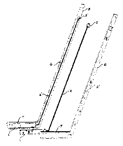
Figure I illustrates a preferred embodiment of the Invention, which comprises
a force
measurement sensor 1 with protective covering 9, transmission carrier 2,
computing unit
3, with display 4, option buttons S, and a system earner 6, with impact area
7, and
CA 02385367 2002-05-07
holding area 8
The transmission carrier 2 is embedded within or affixed to the exterior of
the length of
tilt body of the system carrier so that one end of the transmission carrier 2
is located at the
impact area 7 and the other end is located near the holding area 8. The end of
the
transmission carrier 2 nearest to the impact area 7 is connected to the force
measurement
sensor 1 and the end of the transmission carrier 2 nearest the holding area 8
is connected
to the computing unit 3. The force measurement sensor 1 is attached firmly
within the
impact area 7 of the system carrier 6 and the computing unit 3 is attached in
a convenient
location near the holding area 8 of the system carrier 6 in such a manner that
will not
impede the user's ability to hold the system carrier 6. A protective covering
~ is attached
to the impact area 7, directly over the force measurement sensor 1. The system
carrier 6 is
used to contact an object in such manner that the object contacts the system
carrier 6 in
the impact area 7, preferably near the middle of the force measurement sensor
1. Upon
impact, the force measurement sensor 1 measures the force of the impact of an
object
with the force measurement sensor 1. This force measurement is transmitted to
the
computing unit 3 via the transmission carrier 2. The computing unit 3 receives
the force
measurement and uses this measurement to calculate the estimated velocity of
the object
at impact, and projects the estimated velocity on the display 4. The user may
manipulate
the read-out of the information on the display 4 by pressing the option
buttons 5. Upon
the depression of an option button 5, the computing unit 3 will manipulate the
velocity
measurement according to the desired manipulation. T'he option buttons 5 may
include
manipulations such as turning the display 4 on and off, averaging the velocity
measurements, resetting the computing unit 3, and changing the unit of measure
for the
velocity reading.
The preferred construction is as shown in Fig. 1, wherein the system carrier 6
is split into
two halves and each of the halves includes recesses 1', ?' and 3' defined to
receive the
sensor l, the corner 2 and the computing unit 3 respectively. The recesses are
sized to
hold the respective elements tightly so that inertial forces cannot damage
them.
6
CA 02385367 2002-05-07
All components of the Invention may be comprised of any device and material
suitable,
including but not limited to a force detection sensor comprised of electronic
components
embedded in an elastomeric or plastic covering; a transmission carrier
comprised of
electrical wire or cable; a computing unit housing comprised of metal,
aluminum or
plastic; a computing unit display comprised of a LED display or a LCD; a
system carrier
comprised of wood, aluminum, metal or plastic; and a protective covering
comprised of
elastomeric, plastic or Plexiglas. rChe references incorporated in this
application clearly
define the steps necessary to produce the several elements or components and
to provide
for their interconnection and operation.
Fig. 3 defines the logical operation of the computing unit 3. After power is
turned on, the
unit 3 initializes. This step is very well recognized in the art. The circuit
remains in a
"sleep" low power consumption mode until brought to active mode by the
pressing of any
button 5. This type of circuit is very well I<:nown in the art. Next, the
logic searches for
which key has been activated, including the OFF key, the velocity units
selection key, the
"RESET" key, and the "AVERAGE" key. These produce the actions of: toggling
between kilometers per hour and miles per hour; clearing the display 4; and
calculating an
average, respectively depending upon which button 5 was depressed. Such
operations are
very well known in the art and the circuit elements and configurations needed
to achieve
them are well known as well. If the OFF key has not been actuated and none of
the
foregoing buttons 5 have been activated, as well, the logic reads the signal
from the
sensor 1. If there is none, the cycle repeats. If there is, speed is
calculated and displayed
in accordance with the selected units. Timeout and low battery functions are
provided as
is well known in the art.
The above apparatus may be alternately described as follows. A sport apparatus
comprising: a force measuring means 1 engaged within an impact portion 7 of
the sport
apparatus; a computing and displaying means 3 engaged within a hand-held
portion 8 of
the sport apparatus; and a signal transmitting means 2 joining the force
measuring means
1 and the computing and displaying means 3 for carrying information from the
force
measuring means to the computing and displaying means; the computing and
displaying
7
CA 02385367 2002-05-07
means 3 providing means for converting the signal from the force measuring
means into a
velocity and for displaying said velocity. such converting means is preferably
a
computer calculation using a normalizing factor determined by trial using a
selected force
sensing transponder device such as peizo element, an accelerometer, strain
guage, etc.
Preferably, the computing and displaying means 3 provides functional buttons 5
adapted
for selecting power status, clearing a display screen of the computing and
displaying
means, selecting units of the velocity values displayed on the display screen,
and
averaging plural of the displayed values. Of course, other functions could be
applied as
desired in a particular sport.
Preferably, the sport apparatus is formed of two mating halves which may be
fastened
into an integral unit using any system of fastening known to the art. One, or
both, of the
halves provides a recess 1', 2', 3' :for accepting the force measuring means
l, the
computing and displaying means sand the signal transmitting means 2 in tight-
fitting
engagement; critical to avoid inertial force damage to these components.
While the invention has been described with reference to at least one
preferred
embodiment, it is to be clearly understood by those skilled in the art that
the invention is
not limited thereto. Rather, the scope of the invention is to be interpreted
only in
conjunction with the appended claims.
~3