Note: Descriptions are shown in the official language in which they were submitted.
CA 02385474 2002-03-19
WO 01/25594 1 PCT/N000/00310
Method and plugging material for reducing formation
fluid migration in wells
Particulate matter to hinder/reduce migration of formation
fluids in wells
Subject of the invention
The invention concerns a mixture of particulate matter to
hinder/reduce migration of formation fluids in wells,
primarily in connection with plugging of wells related to
exploitation of hydrocarbons. Formation fluids encompass both
liquids and gases in the sub-terrain.
Known technique
Plugging of wells is on the most part carried out by removing
the production tubing, upper part of well casings and other
superfluous well equipment to the extent that this is
possible and necessary. Simultaneously with or prior to the
plugging, one or several mechanical plugs are placed in the
CA 02385474 2002-03-19
WO 01/25594 2 PCT/N000/00310
well, eventually combined with one or several cement plugs.
The plugs are commonly placed within a few well intervals,
and these represent only a small fraction of the total volume
in the well. Similarly, for example related to production, it
may be required to perform zone isolation in the well by
plugging. The plugging is carried out to hinder eventual
fluids in the formations, including hydrocarbons, from
leaking to the surface or eventually to another formation in
the well, where such leaks would create unwanted and eventual
dangerous situations.
Drawbacks of the known technique.
The conventional technique for plugging of wells usually
requires much work and time and is therefore rather
expensive, especially for offshore wells. Much of the work is
related to preparations before the plugging operation, such
as among others cutting and removal of downhole casings and
production tubing(s). The quality of these preparatory works
have great impact on how efficiently one manages to place
mechanical and/or cement plugs, and on how well the plugs
keep a tight seal afterwards. After the placement in the well
the metal in the mechanical plugs and in the casings
remaining in the well are subjected to corrosion. This will,
in the foreseeable future reduce the thickness of the metal
by corrosion, eventually they crack under the prevailing
physical loads and leakage will occur. Eventual displacements
in the Earth's crust can also damage mechanical plugs and
cement plugs and make them deform and eventually become
fractured. These plugs lack the ability to conform to changes
in their environments and will therefore not maintain their
3o function to hinder flow.
CA 02385474 2002-03-19
WO 01/25594 3 PCT/N000/00310
An article in the Norwegian Petroleum Directorate's (NPD)
magazine 'Sokkelspeilet', No.2, 1999, pp. 12-13, speaks about
the risk for well leaks resulting from Earth crust
displacements, alluded to above, and where the NPD's concern
is to bring forward a method for well plugging that shall
have a sufficient durability that in principle is the
perspective of eternity.
Although NPD in principle wants the perspective of eternity
for the durability of well securing, it is in practice
reasonable to assume that well plugs are never absolutely
tight for all times. Another practical question concerns what
may be viewed as being sufficient well securing.
The purpose of the invention
The purpose of the present invention is to make available a
simple and less expensive method for hindering/reducing
unwanted migration of formation fluids in wells, primarily in
connection with plugging of wells related to the exploitation
of hydrocarbons. The invention also aims at making available
a more flexible and durable plugging of such wells.
How the objective is accomplished
The purpose is, as described in the characteristic in the
present independent and dependent patent claim, realised by
preferably applying a poorly sorted mass of naturally
occurring and/or synthetic produce of granulated material,
eventually like material suspended in a suitable carry fluid,
to be placed suitably in the well, eventually also around
remaining casings in the well, production tubing, eventually
CA 02385474 2002-03-19
WO 01/25594 4 PCT/N000/00310
other equipment left in the well, in the entire or portions
of the well.
The principle behind the method is known from natural
sedimentological processes, and is applied in construction
activities, among others for building of the core of dams
and dikes. The novelty is that the principle is carried
further in the form of a new method whereby a defined mass of
particulate matter constitutes the main, preferred material
for plugging of wells. The application of the method requires
acceptance that a packed particulate matter with low
permeability can form a sufficiently impermeable well plug.
The mass can for example consist of a poorly sorted mixture
of granule, sand, silt and clay. Sorting is among others, a
measure of the degree of variability, or width of variation
of the different particle sizes in the aggregate mass. The
notion of sorting also expresses the distribution of these
particle sizes in the aggregate, that yields a statistical
description by means of a cumulative distribution function.
A poorly sorted particulate matter consists of particles
including several particle sizes. In comparison, a moderately
sorted mass consists of a small number of categories of
particle sizes, for example medium sand and fine sand, while
a well sorted mass includes one category of particle sizes,
for example coarse silt. Other examples of particle size
categories are very coarse sand (particle diameter 1 - 2 mm),
coarse sand (particle size diameter 0.5 - 1 mm), very find
sand (particle diameter 0.0625 - 0.125 mm), fine silt
(particle diameter 0.008 - 0.016 mm), and so forth. These are
examples from the so-called Udden-Wentworth scale of particle
sizes.
CA 02385474 2002-03-19
WO 01/25594 5 PCT/N000/00310
In statistical terms, each particle size category is often
expressed by a variation width given as ~-values, where
~=- logz d ( d = average particle diameter )
As examples, fine silt has ~-values between 6 and 7 and
medium silt has ~-values between 5 and 6. The accompanying
scale of particle sizes is known as the Krumbein phi (~)
scale. The distribution of particle sizes in the mass is
commonly given by the variation width (in ~-values) that
include approximately 2/3 of all the particles in the mass.
Statistically this variation width equals two times the
standard deviation. The standard deviation is therefore a
commonly accepted measure for the sorting of a sediment or a
mass of particulate matter.
Both the Udden-Wentworth scale and the Krumbein ~-scale and
other notions are generally known and applied within among
others, geological disciplines. There are also other similar
scales and/or terminology that in varying degrees are used
within different geographical areas and/or engineering
disciplines.
The composition of the mentioned particulate material mass
must be adapted to the well conditions and objectives one
wishes to accomplish for the individual well. There may also
be conditions where the composition of the particulate matter
can be varied along the length of the well if this appears to
be preferable. The mentioned particulate matter mass
replaces, eventually is used in combination with conventional
mechanical plugs and/or cement plugs, eventually also in
CA 02385474 2002-03-19
WO 01/25594 6 PCT/N000/00310
combination with other plug types containing e.g. resin or
similar additives.
After placement in the well, the particulate matter should
over a large length in the well be such sorted, packed and
eventually contain a sufficiently irregular form, such that
appreciable migration of formation fluid is hindered.
Alternatively, the same effect can be achieved by placement
of a homogenous and fine-grained particulate matter, such as
silt and/or clay in the well. This lastly named alternative
however appears impractical since the placement of such a
mass would be far more time consuming, and the fine grains
require a long time to sediment from the fluidised mass. The
mixed in fluid, a so-called carry fluid, must also have
viscosity, specific gravity and/or other physical/chemical
properties designed for the/those specific objectives one
wants to achieve.
The low permeability of the particulate matter results in
that a fluid front will move slowly through the mass. The
velocity of the fluid front through the particulate material
is controlled by adapting the composition of particle sizes
and the length of the particulate material plug(s) according
to the properties of the migrating fluid, for example the
viscosity, such that the time to migrate through becomes
acceptably long. In addition the gravitational force of the
Earth will over time further pack the particles together,
similar to the physical changes that occur in a naturally
deposited sediment after the sedimentation. In this regard,
it is theoretically possible to obtain a time for migrating
through of more than 1000 years for a formation fluid
migrating from a depth of more than 1000 metre under the
solid surface of the Earth.
CA 02385474 2002-03-19
WO 01/25594 7 PCT/N000/00310
Darcy's Law describes the parameters and the relation that
influence on the migration front velocity through a porous
and permeable material;
v = k = ( pin - Pout ) / ([x = L ) ; where,
v - the migration velocity of the fluid (in cm/sec)
k - the effective permeability to the fluid in the
material (in Darcy)
pin - the inlet pressure (in atmospheres)
Pout - the outlet pressure (in atmospheres)
- the kinematic viscosity of the flowing fluid (in
centiPoise)
L - the length of the permeable material (in cm).
As an illustration of this, calculations performed on the
premise of a 3000 metre long vertical well from a depleted
reservoir where the pore pressure can build up to 300
atmospheres and where the permeability of the particulate
matter plug has a permeability of 0.001 Darcy and the pores
in the plug are full initially of fresh water, show that it
would take more than 20,000 years for the reservoir fluid to
migrate from the reservoir to the surface. If the plug's
pores were initially full of seawater the time to migrate
through would be about 60,000 years. These calculations
premise static parameters and that these do not change with
time. We know that naturally deposited sediments become
CA 02385474 2002-03-19
WO 01/25594 8 PCT/NO00/00310
subjected to physical and chemical changes, so-called
diagenetic changes, that over geological time commonly lead
to solidification of sediments. It may therefore be justified
to assume that a plug of particulate material will also be
subjected to such changes and that the porosity of the plug
and its permeability will gradually decrease, which in due
course results in increasing degree of hindering/reducing the
migration of formation fluids through the plug. Earth crust
movements can for example lead to that a partially or totally
petrified mass becomes fractured, and that formation fluids
then flow through the fractures upwardly in the well.
However, we know that diagenetic changes usually happen in
the run of thousands of years or more. It is therefore most
probable that the plug will remain deformable in such a time
perspective and that it will conform to eventual changes in
the geometry of the well and that it will thus maintain its
function as a plugging material.
It is possible to design most of the parameters in the Darcy
Law. The permeability in the particulate matter plug is a
function of the sorting and the packing of the particles. In
addition the permeability is relative to the pore saturation
of the flowing fluid, in the oilfield terminology called the
relative permeability. The length of the plug(s) is also
controllable. The pore fluid of the plug may also consist of
fluid thickening substances that increase the viscosity of
the fluid. =
According to Darcy's Law a fluid will not flow through a
permeable material if the pressure drop across (pin - Pout) _
0, eventually if the product ( =L) =oo. The pressure drop
can simply be eliminated by placing a suitable liquid over a
sufficient well length to obtain a hydrostatic head pressure
CA 02385474 2002-03-19
WO 01/25594 9 PCT/N000/00310
equal to the pressure of the formation fluid. Strictly
theoretical this should be sufficient to prevent formation
fluids from entering into the well. In practise the pressure
in the reservoir fluids will change slightly over time, and
in addition the hydrostatic pressure from the liquid
mentioned above may also change over time, for example as a
consequence of leaks to/from the surrounding formations in
the ground. Under these conditions for a liquid filled well a
pressure drop may develop with a resulting flow of formation
fluids up through the well. A plug of particulate material
will hinder/reduce such a leak in the future.
The placement of a plug of particulate matter in a well can
be most easily done by mixing the particulate matter with a
suitable liquid to make it possible to pump or dump as a
slurry. The mass can for example be pumped through the
production tubing simultaneously with it being removed from
the well, eventually that the slurry in a suitable way is
pumped into the well after the production tubing being
removed. In some cases, for example for placement of a
particulate mass containing a large fraction of clay it may
be necessary to gradually build a plug by repeatedly lowering
by wire line a cartridge containing the particulate mass, in
a bailer, and dump the mass in the well. Oftentimes one plug
wells with wellhead pressure higher than 1 atmosphere. Then
it may be necessary to utilise high pressure operating
technique, so-called snubbing, in order that the well
operation is done in full control. Such snubbing technique
can for example be done with a snubbing unit, coiled tubing
or drill-pipe. When the production tubing is removed and when
it is impossible to inject a carry fluid into an underground
reservoir, using a coiled tubing may be the quickest and most
applicable way for placing a long particulate matter plug,
CA 02385474 2002-03-19
WO 01/25594 10 PCT/N000/00310
whether it is for wells with the wellhead on a platform, at
the seabed or on land. For plugging when a drill rig is
available the placement of a particulate matter plug through
ordinary drill-pipes may be the most practical and economical
way. The technique for placement of the particulate matter
plug will be evaluated for each individual well with respect
to the mechanical conditions of the well and with regard to
what equipment is available.
The well will be filled to the required extent, preferably by
a fluidised mass that after placement and in its final form
is a more rigid but still malleable material. Into the
particulate matter can eventually be added ingredients that
result in concentration and flocculation and more rapid
sedimentation of the smallest particles, such as clay
particles.
Advantages that are achieved through the invention
In addition to the long time for a fluid front to migrate
through the particulate matter plug(s), the plug has the
ability to largely remain in a malleable state for a long
period after the placement. This ability infers that the
particulate matter plug can adapt itself to eventual changes
in the geometry of the well and thus will maintain its
function as a plug. Such changes can appear as a consequence
of displacements in the Earth's crust, where the
displacements may be caused by larger, naturally occurring
Earth crust movements or as a consequence of production
related changes in a reservoir. Volumetric changes may also
take place as a result of corrosion of the metal in the well.
CA 02385474 2007-08-24
11
A further advantage with the invention is achieved when such
a particulate matter is utilised for temporary plugging of a
well. For subsequent need, it is much easier and cost
effective to remove this plug than to remove mechanical
and/or cement plugs.
Furthermore, the particulate matter plug may partly
utilise/consist of drill cuttings from the well itself,
eventually also from other drill holes. Then an otherwise
often problematic disposal product from drilling operations
may have a useful and cost saving utilisation.
The particulate material's pores can after placement in the
well be filled by a salty liquid (brine), for example when
the carry fluid consists of a salty liquid. The fluid will
then exert a hydrostatic pressure in the drill-hole that in
is itself may represent a complete pressure barrier against the
formation's pore pressure.
Short description of the drawings
In the following part of the description and with referencing
to the set of figures, will be referenced to 3 different
figures, where two figures depict the conventional technique
and one figure shows an example of using the invention. One
reference number refers to,the same. detail in all the figures
where such.a detail is shown, and where:
Fig. 1 shows a schematic cross section of how a typical
prior art producing well is built;
CA 02385474 2007-08-24
12
Fig. 2 shows a schematic cross section of how a typical prior
art production well is plugged in the conventiorral manner;
Fig. 3 shows a schematic cross section of production well
where the production tubing has been removed, and where
particulate material constitutes the majority of the well
plugging.
All the figures are very much off scale as concerns physical
dimensions, lengths and component details.
Description of performance methods
The invention concerns as stated above a method to hinder/
reduce migration of formation fluids in wells, primarily in
connection with plugging of wells related to exploitation of
hydrocarbons. Well equipment and/or conditions that do not
directly concern the invention itself, but that are necessary
1s pre-conditions for being able to apply the invention, are not
given or described in detail as these are well known to the
professional persons.
Figure 1 is included as a reference in order to illustrate a
typical construction of a production well. The well consists
of a series of drilledintervals where each subsequent
interval has a smaller bore hole diameter than the previous
one in the more shallow interval. Each bore hole diameter
interval is equipped with an accompanying casing 10, 12, 14
and 16 inside the/those previous and more shallow casing(s)
10,'12 or 14. Such casings 10, 12, 14 and 16 are usually
ending in a wellhead placed at the surface. The deepest and
last casing 18 in the lower section penetrates and runs
through a reservoir 20, while the upper end is fastened
CA 02385474 2002-03-19
WO 01/25594 13 PCT/N000/00310
inside the lowest part of the previous casing 16. When this
casing 18 does not extend to the surface, it is commonly
referred to as a liner. The annuli between the drilled hole
wall 22 and the casings 12, 14 and 16, are commonly filled
totally or partly by cement 24. In locations where it is
possible, the shallowest casing 10 is usually driven down
into the shallow material below the surface, without a
subsequent cementing.
The communication with and production from the reservoir 20
io comes through at least one perforation 26 through the liner
18 and the cement around it 24 (or from open hole section,
'barefoot completion'). In this example the reservoir fluid
is produced through the liner 18 and further into a
production tubing 28. The direction of flow is in figure 1
given by arrows. Further, near the surface and inside the
production tubing 28 is placed a down-hole safety valve 30.
The production tubing 28 is fixed to the casing 16 by means
of a production packer 32. The production packer 32 is
equipped with one or several sealing elements 34 to avoid
that the reservoir fluids can flow from the reservoir 20 and
into the annulus 36 between the production tubing 28 and the
casing 16. The production packer 32 has in the upper end also
an internal diameter that makes it possible to enter and
connect with the lower part of the production tubing 28, and
this end is equipped with external, packing rings 38 to
achieve a pressure tight connection. Such a configuration
likewise makes a disconnect easy of the production tubing 28
from the production packer 32. The lower part of the
production packer 32 functions as the inlet for produced
reservoir fluids and is often made with a smaller diameter
than the upper section. The lower section often has a special
CA 02385474 2002-03-19
WO 01/25594 14 PCT/N000/00310
made form in order to more easily be able to run for example
well maintenance equipment through this bevelled opening and
in or out of the production tubing 28.
Conventional plugging of such a production well is shown in
the figure 2. In this example the production tubing 28 is
disconnected and removed. A mechanical plug 40 is covered
right on top by a cement plug 42, is placed right above the
perforations 26 inside the liner 18. The casing 16 is plugged
above the production packer 32 by a mechanical plug 44 and a
cement plug 46 directly on top. The upper portion of the
casing 16 has in this example been removed. A mechanical plug
48 is set in the casing 14 right above the cut end of the
casing 16. One or several longer cement plugs 50 are then
placed above the mechanical plug 48 in the remaining casing
14 volume until close to the sea-bottom, eventually to the
land surface.
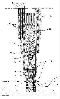
Figure 3 shows one example of application of the invention,
where a production well is plugged by particulate matter
through the majority of the length after the production
tubing is removed. In this example a continuous plug of
particulate matter 52 is placed in the liner 18 and further
all the way in the casing 16. A cement plug 50 on the top can
eventually be placed as a seal over the particulate matter
plug 52, eventually to the land surface.