Note: Descriptions are shown in the official language in which they were submitted.
CA 02385678 2008-07-29
1
DESCRIPTION
METHOD AND APPARATUS FOR DETECTING ULTRASONIC SURFACE
DISPLACEMENTS USING POST-COLLECTION OPTICAL AMPLIFICATION
TECHNICAL FIELD OF THE INVENTION
The present invention relates generally to a system and method of non-
destructive evaluation
of materials, and more particularly, to a system and method of processing
optical information to
detect ultrasonic surface displacements through the use of at least one laser
and optically amplifying
the scattered return of laser light after collecting it to perform a non-
destructive evaluation of a
material.
BACKGROUND OF THE INVENTION
In recent years, the use of advanced composite structures has experienced
tremendous growth
in the aerospace, automotive, and many other commercial industries. While
composite materials offer
significant improvements in performance, they require strict quality control
procedures in the
manufacturing processes. Specifically, non-destructive evaluation ("NDE")
methods are required to
assess the structural integrity of composite structures, for example, to
detect inclusions, delaminations
and porosities. Conventional NDE methods, however, are very slow, labor-
intensive, and costly. As
a result, testing procedures adversely increase the manufacturing costs
associated with composite
structures.
Various systems and techniques have been proposed to assess the structural
integrity of
composite structures. One method to generate and detect ultrasound using
lasers is disclosed in U.S.
Patent 5,608,166, issued March 4, 1997, to Monchalin et al. (the "166
Patent"). The '166 patent
discloses the use of a first modulated, pulsed laser beam for generating
ultrasound on a work piece
and second pulsed laser beam for detecting the ultrasound. Phase modulated
light from thc. second
laser beam is then demodulated to obtain a signal representative of the
ultrasonic motion at the surface
of the work piece. A disadvantage of such a system has been that in order to
improve the systems
ability to detect ultrasonic motion at the surface of the work piece a more
powerful laser is required
which may be impractical to construct or could damage the work piece due to
excessive heating.
Another method to generate and detect ultrasound using lasers is disclosed in
US 6,633,384 issued October 14, 2003 to T.E. Drake entitled "Method And
Apparatus
for Ultrasonic Laser Testing" hereafter DRAKE. DRAKE discloses the use of a
first
modulated, pulsed laser beam for generating ultrasound on a work piece and a
second pulsed laser
beam for detecting the ultrasound. Phase modulated light from the second laser
beam is then
demodulated to obtain a signal representative of the ultrasonic motion at the
surface of the work
piece. A disadvantage of such a system has been that in order to improve the
systems ability to detect
CA 02385678 2002-03-19
WO 01/27606 PCT/USOO/41128
2
ultrasonic motion at the surface of the work piece a more powerful laser is
required which suffers
from the same problems as the '166 patent.
Another method to generate and detect ultrasound using lasers is disclosed in
U.S. Patent
5,137,361, issued August 11, 1992, to Heon et. al. (the "361 Patent"). The
`361 patent discloses the
use of a laser to detect deformations of a oscillatory or transient nature on
a remote target surface.
The deformations on the remote target surface can be produced by an ultrasound
wave or other
excitation. Light from the laser is scattered by the deformations, some of
which light is collected by
collecting optics and transmitted via a fiber optic to a beam splitter which
deflects a small portion of
the collected light to a reference detector and delivers the remaining portion
of the light to a confocal
Fabry-Perot interferometer, which generates an output signal indicative of the
deformations on the
remote target surface. The reference detector measures the intensity of the
scattered laser light at the
input of the interferometer to generate a reference signal. A stabilization
detector measures the
intensity of the scattered laser light at the output of the interferometer to
generate a prestabilization
signal. The ratio of the reference signal to the prestabilization signal is
used to generate a final
stabilization signal which drives a piezoelectric pusher inside the
interferometer to adjust its resonant
frequency. A disadvantage of such a system has been that a portion of the
signal is lost at the beam
splitter when sent to the reference detector. Again in order to improve the
systems ability to detect
ultrasonic motion at the surface of the work piece a more powerful laser is
required.
An alternate to using a more powerful laser is to decrease the working
distance to the part
and/or increase the collection aperture size. This reduces the F-number of the
optical system and has
the disadvantage of a corresponding reduction in the working depth of field
(DOF). DOF is a measure
of how far away from the ideal focal plane an object can be and still maintain
acceptable performance.
Lower F-number designs generally result in smaller scan area capability and
often require active
focusing lens assemblies to maintain efficient light collection while scanning
complex shaped
components. Large collection apertures require the use of single-mirror
optical scanning systems,
usually in a two-axis gimbal configuration, that are cumbersome and generally
slow.
Moreover, there is a need for a ultrasonic laser system which improves
detection capabilities
of the system to detect ultrasonic motion at the surface of the workpiece
using practical lasers without
damaging the workpiece and functioning with sufficiently large DOF.
SUMMARY OF THE INVENTION
The present invention provides a system and method for detecting ultrasonic
surface
displacements on a remote target that substantially eliminates or reduces
disadvantages and problems
associated with previously developed laser ultrasonic systems and methods.
More specifically, the present invention provides a system and method for
detecting
ultrasonic surface displacements on a target. The system for detecting
ultrasonic surface
CA 02385678 2002-03-19
WO 01/27606 PCTIUSOO/41128
3
displacements on a target includes a detection laser to generate a first
pulsed laser beam to detect the
ultrasonic surface displacements at the remote target. Collection optics
collect the phase modulated
light from the first pulsed laser beam scatered by the remote target.
Scattering of the laser beam by
the remote target includes all reactions between laser beam and the remote
target where the laser
beam is redirected with phase modulations induced by surface vibrations or
perturbations such as
those produced by ultrasonic mechanisms.
An optical amplifier amplifies the phase modulated light collected by the
collection optics.
This optical signal is in turn processed by an interferometer to process the
phase modulated light and
generate at least one output signal. Furthermore, a processor processes the at
least one output signal
to obtain data representative of the ultrasonic surface displacement on a
remote target.
Another embodiment of the present invention includes a method for detecting
ultrasonic
surface displacements. This method includes the steps of first generating
ultrasonic surface
displacements at a remote target. These ultrasonic displacements at the remote
target scatter the first
pulsed laser beam creating a phase modulated return. This phase modulated
light from the first pulsed
laser beam either reflected or scattered by the remote target is then
collected and optically amplified.
This signal is processed to obtain data representative of the ultrasonic
surface displacements at the
remote target.
A technical advantage of the present invention is that an improved method for
ultrasonic laser
testing is provided. That provides rapid, non-contact, and non-destructive
inspection techniques that
can be applied to complex composite structures. The present invention provides
a flexible, accurate
and cost effective method for inspecting complex composite structures that is
able to rapidly scan and
test large-sized composite structures.
Another technical advantage of the present invention is an improved signal-to-
noise ratio for
the test system due to increased detection intensities reducing the required
intensity of the detection
laser.
Another technical advantage of the present invention is the ability to use a
detection laser
with lower output power.
Another technical advantage of the present invention is the possibility of an
increased
working distance between the target object and the scanner by optically
amplifying the phase
modulated light.
Yet another technical advantage is eliminating the need for active focusing
elements due to
the increased depth-of-field, which increases scan coverage, and is compatible
with small-aperture
high-speed optical scanners.
CA 02385678 2008-07-29
4
BRIEF DESCRIPTION OF THE DRAWINGS
For a more complete understanding of the present invention and advantages
thereof, reference
is now made to the following descriptions taken in conjunction with the
accompanying drawings in
which like reference numbers indicate like features and wherein:
FIGURE 1 illustrates a known setup for detecting ultrasonic surface
displacements using a
detection laser beam;
FIGURE 2 is a typical gain plot for an optical amplifier illustrating laser
output versus
number of passes through the amplifier;
FIGURE 3 illustrates the use of a post-collection multipass optical amplifier
to yield an
improved signal-to-noise ratio;
FIGURE 4 illustrates the use of doped fiber optic and an optical pump for post-
collection
optical amplification;
FIGURE 5 illustrates a setup for testing the gain associated with post-
collection optical
amplification;
FIGURE 6 illustrates reflected and transmitted signals generated using the
setup of FIGURE
5 without post-collection optical amplification; and
FIGURE 7 illustrates reflected and transmitted signals generated using the
setup of FIGURE
5 with post-collection optical amplification.
DETAILED DESCRIPTION OF THE INVENTION
Preferred embodiments of the present invention and its advantages are
understood by
referring to FIGUREs 1 through 7 of the drawing, like numerals being used for
like and
corresponding parts of the various drawings.
FIGURE 1 illustrates a known setup for generating and detecting ultrasonic
surface
displacements using a detection laser beam. Detection system 100 utilizes a
detection laser 120 to
detect ultrasonic surface displacements on a remote target. Detection laser
120 may incorporate a
continuous wave (cw) single longitudinal-mode (SLM) seed laser along with a
multi-pass optical
amplifier to generate a laser beam 125 with a power Po. The ultrasonic surface
displacements in the
remote target 110 modulate, scatter and reflect detection laser beam 125,
represented by arrows
directed away from the remote target 110. When detection laser beam 125
interacts with the
ultrasonic waves present in the remote target 110, detection laser beam 125 is
reflected as phase-
modulated light. Specifically considering the electric field representation of
an incident laser beam
125 as:
E = E . e'(ox-kx)
to
CA 02385678 2002-03-19
WO 01/27606 PCT/USOO/41128
where E is the electric field amplitude, co is the radial frequency, t is
time, the wave vector is defined
as k = IT
, A is the wavelength, and x is the distance traveled to the target. Beam 125
is scattered or
reflected from a surface 110 experiencing a time dependent displacement O(t) ,
and returns along the
same path, producing a modulated electric field for A(t) << A defined as:
5
E,,, = E = [l - 2ikO(t)]e'
The A(t) term must be demodulated using interferometer 150 from this
expression for reconstruction
of the time history of the surface displacement. Some of the phase modulated
light is captured by
collection optics 130, which directs the phase-modulated light via fiber optic
140 into interferometer
150. Interferometer 150 demodulates the phase-modulated light and directs its
outputs into detector
160 which generates an analog signal for processing.
Collection optics 130 has an aperture diameter of 4 and is spaced a distance D
from remote
target 110. The power of the collected, phase-modulated light as measured at
the output of the
collector is Pe, and therefore, the power at the input of the interferometer
is substantially Pe since there
is very little transmission loss associated with fiber optic 140. A typical
diffuse surface will have the
following relationship describing the amount of collected light for a
specified optic diameter and
working distance:
z
P~ = 4 D)(I - A)cos(B)
Where A represents the absorption of the target and 0 is the angle of
incidence. A perfect white
diffuse target would have A = 0, and a typical dark composite might have an
absorption of 90% (A =
0.9). Because the loss in interferometer 150 is minimal, the power of the
input signal to the detector
(PDET) is substantially the same as P.
The signal-to-noise ratio for shot-noise limited performance of detector 160
is directly
proportional to the square root of the input power:
SNR = /R2Pdet
2eBW
where R, is the responsitivity of the detector, e the electron charge, and BW
is the electrical
bandwidth. It is assumed that the electrical bandwidth of detector 160 is
restricted to be the smallest
CA 02385678 2002-03-19
WO 01/27606 PCT/US00/41128
6
possible for the measurement of interest and that detector 160 is near optimal
for the intended
wavelength.
The formula above suggests that the SNR can be improved by increasing P0, or
~, or by
decreasing D. Increasing the ratio of ~/D (lowering the F-number) will
decrease the depth of field of
detection system 100, which is undesirable because a decreased depth of field
is less flexible and may
necessitate the use of active focusing optics.
Alternatively, P0 can be increased. One approach to increase the output of
detection laser 120
is to use a shorter pulse width while maintaining the same pulse energy
thereby increasing the peak
power. The pulse of detection laser beam 125, however, must be of a sufficient
duration to permit
detection of ultrasonic surface displacements for materials with various
thickness, and therefore,
decreasing its pulse duration degrades its ability to detect such
displacements on a variety of
materials. A second approach is to amplify the detection laser using a
multiple pass optical amplifier.
However, the gain of a conventional optical amplifier is dependent upon the
power of the input signal.
FIGURE 2 illustrates a gain plot 200 for a typical optical amplifier as a
function of the number of
passes through the amplifier. Gain plot 200 shows that the typical amplifier
has a linear gain 210 for
small input signals. However, the gain 220 is not linear as the input signal
increases, as illustrated by
the leveling of gain plot 200 as the amplifier approaches saturation. Gain
plot 200 demonstrates that
adding multiple amplifier passes quickly reaches a point of diminishing
returns, and therefore, the
ability to increase SNR by increasing P0, is limited. Adding more amplifier
sections to further
increase output power is very costly. Cost will increase in direct proportion
to the power addition, to
double power will double cost.
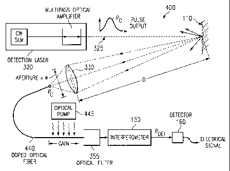
FIGURE 3 illustrates a setup for a new and improved detection system 300.
Detection
system 300 utilizes a detection laser 320 to detect ultrasonic surface
displacements in a remote target
110. Detection laser 320 may incorporate a multi-pass optical amplifier to
generate a laser beam 325
with a power Po.
The ultrasonic surface displacements, O(t) , in a remote target 110 may be
produced using a
generation laser, a piezoelectric transducer, electrical discharge, projectile
impact or other known
means. The ultrasonic surface displacements modulate, scatter and reflect
detection laser beam 325.
When detection laser beam 325 interacts with the ultrasonic waves present at
the remote target 110,
detection laser beam 325 is reflected as phase-modulated light, as illustrated
by the arrows directed
away from remote target 110.
When a generation laser is used to induce ultrasonic surface displacements,
the generation
laser must be of a frequency that is readily absorbed into the remote target
110 without causing
ablation or breaking down the remote target material, and it must be of
sufficient pulse length to
induce ultrasonic surface deformations. For example, a transverse-excited
atmospheric ("TEA") CO,
laser can be used to produce a 10.6 micron wavelength beam for a 100
nanosecond pulse. The power
CA 02385678 2002-03-19
WO 01/27606 PCT/US00/41128
7
of the laser must be sufficient to deliver, for example, a 0.25 joule pulse to
the remote target, which
may require a 100 watt laser operating at 400Hz pulse rate. The generation
laser should be absorbed
as heat into the remote target thereby causing thermoelastic expansion without
ablation. Optionally,
the generation laser and the detection laser may also be applied coaxially to
the surface of the remote
target object.
The detection laser 320 must be of a sufficiently long pulse duration that it
does not induce
ultrasonic surface displacements. For example, a long-pulsed Nd:YAG laser can
be used. The power
of this laser must be sufficient to deliver, for example, a 20 milli joule,
100 microsecond pulse,
which may require 200 watt peak power laser.
When detection laser beam 325 interacts with the ultrasonic waves present in
remote target
110, detection laser beam 325 is reflected as phase-modulated light. Some of
the phase modulated
light is captured by collection optics 330. Collection optics 330 may utilize
either a large aperture
collector or a small aperture collector. For example, a large aperture
collector may be a Cassegrain-
type reflector, comprised of a primary reflective surface which directs light
upon a secondary
reflective surface, which in turn, focuses the light into fiber optic 140. For
increased speed and
flexibility, however, a small aperture collector is desirable typically of a
refractive doublet
construction. The optical invariant or etendue should be appropriately matched
between the collection
optic 330 design and the collection fiber optic 140.
Collection optics 330 collect the phase-modulated light and directs it into
fiber optic carrier
140, which in turn, directs the phase-modulated light through optical isolator
assembly 335 into
optical amplifier 345. Isolator assembly 335 is employed to minimize the
possibility of self-
oscillation of the amplifier 345 due to Fresnel reflections form the
collection fiber 140 end face. The
amplified, phase-modulated light is directed through an optical filter 355.
Optical filter 355 is
employed, as necessary, to reduce noise generated in amplifier 345. The
amplified and filtered, phase-
modulated light is then directed into interferometer 150, wherein the light is
demodulated. The
demodulated light is then directed into an electro-optic attenuator 370, to
manage the light intensity,
and finally into detector 160 which generates an analog output signal.
Optionally, an optical ranging unit (not shown) can be integrated into
detection system 300 to
utilize a ranging laser beam to determine the distance between the remote
target 110 and the scanning
system. Often, it is important to know the distance by which remote target 110
is located from the
scanner so that a topographical contour can be created for the remote target
and can be correlated to
the optical data being collected. Generally, this correlation is recorded on a
point-by-point basis.
The power of the collected, phase-modulated light as measured at the output of
the collector
is Pc, and optical amplifier 345 has a gain G. Therefore, the power of the
signal at the output of
optical amplifier is Pc * G.
CA 02385678 2002-03-19
WO 01/27606 PCT/US00/41128
8
The post-collection amplification process must be analyzed for linearity,
bandwidth and noise
performance to determine suitability for a particular application. As noted in
Figure 2, these
amplifiers will be suitable for linear, undistorted, amplification of small
input signals, and the known
saturation effects could be removed by post-processing if operated at higher
input levels. In regard to
bandwidth, as an example, Nd:YAG has a spontaneous-emission spectrum width on
the order of 150
GHz. Gain bandwidth narrowing of the 150GHz Lorentzian line-shape can reduce
the bandwidth
down to values as low as 30GHz for very high gain amplification. The effective
optical bandwidth
d v can be deinied as:
dv = dv 1 3
F G-3
where d v is the spontaneous-emission line width, F is the filter 355
finesse, and G is the amplifier
345 gain in dB.
Thus, even at high gains, this method will function for ultrasonic frequencies
of interest,
which usually are below 100MHz. As an example, composite material testing only
requires a 10MHz
bandwidth.
Noise contribution from the optical amplifier can be described using the Noise
Equivalent
Power (NEP) approach where the amplifier output noise is referenced back to an
equivalent amount
of signal that would produce the observed noise level. The source of the
amplifier noise is due to
amplified spontaneous emissions (ASE), which are fundamental to all optical
amplifiers. Four-level
amplification systems are superior to three-level systems in this application
due to the transitions
occurring down to relatively unpopulated levels thereby a minimum number of
ASE producing
inverted states are necessary for a particular gain requirement. The NEP for
an optical amplifier 345
that is etendue matched to a collection fiber optic 140 is given as:
NEP = 2h v(d v) za NAn
Where h is Planks constant, v is the optical frequency, d v is the optical
bandwidth (including gain
narrowing and filtering processes), a is the half-diameter of the collection
fiber optic 140, NA is the
numerical aperture of 140, n is the index of refraction of the gain medium
345, and A is the optical
wavelength. It is possible to reduce the NEP by optical filtering with 355 to
lower the gain-narrowed
bandwidth from 30GHz down to 1GHz using a simple plane fabry-perot device with
a finesse of 30.
Further reduction is possible if necessary, potentially matching the desired
electrical bandwidth BW.
CA 02385678 2002-03-19
WO 01/27606 PCT/US00/41128
9
Two primary noise terms must be considered at the electrical detector. First,
both the signal
and the ASE will generated shot-noise in the detector, although by employing
optical filter 355 it is
possible to reduce the ASE sufficiently below Pc such that all shot-noise
contributions are dominated
by that produced by the signal component alone. A design goal might be to
maintain the ASE at least
one-third of the signal level for the weakest predicted value of Pc.
The second noise contribution occurs from hetrodyne mixing of the ASE with the
signal
within the electrical bandwidth of the detector. This noise is not reduced by
optical filtering, although
it is common-mode and can be reduce through the use of a differential
interferometr 150, where the
hetrodyne noise can be subtracted from a pair of balanced detectors.
Noise performance is often limited by the relative intensity noise (RIN) of
the continuous-
wave (cw) single-longitudinal mode (SLM) laser that is part of detection laser
320. This noise term is
also common-mode and can be reduced by using a differential interferometer
150.
Neglecting common-mode noise terms due to RIN and hetrodyne mixing, the signal-
to-noise
ratio of detector 160 is directly proportional to the square root of the input
power and increases with
amplifier gain G in the limiting case where the NEP << Pc:
SNR = GR~ PC
P + NEP)
2e(P
The introduction of the optical amplifier to amplify Pc, however, permits the
SNR to be improved by
increasing Pdet, in addition to increasing Po, or 0, or by decreasing D. There
are several added
advantages, however. It is no longer critical to increase P,, to the maximum,
and therefore, any
amplifier that amplifies detection laser 320 such that Pc >> NEP can be
employed. For some system
configurations, it is possible for a cw SLM laser to provide sufficient
performance that laser 320
could operate without an amplifier section. Moreover, optical amplifier 345
can also be operated in
the efficient, linear gain region where gains of 100dB are possible. The
increased performance
associated with a two amplifier approach (one amplifier in detection laser
120, and one amplifier post-
collection), will permit the system to use a smaller aperture and a greater
distance D, therefore,
providing detection system 300 with greater flexibility without any
degradation in performance. On
the contrary, detection system 300 enjoys increased performance.
Moreover, optical amplifier 345 will not contribute any substantial additional
noise unless Pe
<< NEP.. Thus, the post-collection optical amplification approach improves the
SNR without any
substantial increase in noise. Electrical amplification of the analog signal
subsequent to detector 160,
however, will not improve the SNR above P. This is so because both the signal
and the noise
component will be amplified. The following example illustrates embodiments of
the present
invention, but should not be viewed as limiting the scope of the invention.
CA 02385678 2002-03-19
WO 01/27606 PCTIUSOO/41128
Consider a laser 320 that produces a peak output power of 100W, a collection
optic 330 that
is 45mm in diameter operating at a distance D of 3000mm from the target which
has an absorption of
90%. The collected light Pc is coupled with a 50% efficiency to a 200um fiber
optic 140 with a
NA=0.22. In this example, the collection fiber optic 140 is slightly
underfilled, but provides a large
5 DOF. Using a filter 355 finesse of 30 for a Nd:YAG amplifer 345 with index
1.8 and wavelength of
1064nm we arrive at a NEP = 5uW and a Pc = 280uW. After polarization effects
are factored, both
the NEP and Pc will typically be half but the ratios remain unchanged.
Assuming an amplifier gain G
=100,000 with a 20% efficiency after passing through the filter 355 and other
optical components
there will be approximately 2.8W of signal power to be processed by
interferometer 150 and possibly
10 reduced in intensity by attenuator 370 prior to reaching signal detectors
160. In this example, the
noise performance would be dominated by residual RIN from the cw SLM laser,
yet can function at
very large distances with a small collection aperture.
FIGURE 4 illustrates a second embodiment to achieve post-collection optical
amplification.
The setup illustrated in FIGURE 4 is very similar to that presented in FIGURE
3, and therefore, only
the differences will be discussed here. Collection optics 330 collect the
phase-modulated light and
direct it into a doped fiber optic carrier 440, which in turn, directs the
phase-modulated light into
interferometer 150, wherein the light is demodulated. The demodulated light is
then directed into
detector 160 which generates an analog output signal. An optical pump 445 is
coupled to doped fiber
optic carrier 440, and acts as an amplifier to increase the power of the
signal. The amplified, phase-
modulated light is directed through optical filter assembly 355 prior to being
delivered to
interferometer 150. The combination of doped fiber optical carrier 440 and
optical pump 445 results
in an effective gain of e2 . Of course, a specific optical amplifier is not
critical to the present
invention, and therefore, other known optical amplifiers may be used.
FIGURE 5 illustrates a setup for testing the use of post-collection optical
gain approach of the
present invention. Detection laser 520 generates a detection laser beam 525
which is directed upon a
remote target 510 to detect ultrasonic surface displacements thereon.
Detection laser beam 525 is
amplified by two external amplifiers 521, 522 before being directed upon
surface 510.
In this test setup, the ultrasonic surface displacements in remote target 510
are produced using
a piezoelectric transducer 515, which transducer is synchronized using
synchronizing means 570.
The ultrasonic surface displacements modulate, scatter and reflect detection
laser beam 525. When
detection laser beam 525 interacts with the ultrasonic waves present in remote
target 510, detection
laser beam 525 is reflected as phase-modulated light from remote target 510.
The reflected, phase-
modulated light is collected and directed into optical amplifier 545 where it
may be amplified if
desired, or may be passed through without amplification, depending on whether
amplifier 545 is
active or inactive. From amplifier 545, the light is directed via fiber optic
140 into interferometer
150, wherein the reflected and transmitted components of the signal are
detected using detectors 560A
CA 02385678 2002-03-19
WO 01/27606 PCT/US00/41128
11
and 560B, respectively. Detectors 560A and 560B generate analog signals which
are then captured
for comparison by measurement device 580.
FIGURE 6 illustrates the reflected and transmitted signals as detected when
amplifier 545 is
inactive, and thus, passes the collected, phase-modulated light without
amplification.
FIGURE 7 illustrates the reflected and transmitted signals as detected when
amplifier 545 is
active, and thus, amplifies the collected, phase-modulated light. A comparison
of the signals
illustrated in FIGUREs 6 and 7 demonstrates that the reflected and transmitted
signals have been
amplified significantly without any substantial increase in noise.
Although the present invention has been particularly shown and described in
detail, it should
be understood that various changes, substitutions and alterations can be made
hereto without
departing from the spirit and scope of the invention as defined in the
appended claims.