Note: Descriptions are shown in the official language in which they were submitted.
CA 02385788 2002-03-21
WO 01/27371 PCT/US00/01973
METHOD AND APPARATUS FOR MAKING A NONWOVEN
FIBROUS ELECTRET WEB FROM FREE-FIBER AND POLAR LIQUID
The present invention pertains to a method that uses a polar liquid to charge
nonconductive free-fibers to form an electrically-charged nonwoven fibrous
web. The
present invention also pertains to an apparatus that is suitable for making
such a web.
BACKGROUND
Electrically-charged nonwoven webs are commonly used as filters in respirators
to
protect the wearer from inhaling airborne contaminants. U.S. Patents
4,536,440,
4,807,619, 5,307,796, and 5,804,295 disclose examples of respirators that use
these filters.
The electric charge enhances the ability of the nonwoven web to capture
particles that are
suspended in a fluid. The nonwoven web captures the particles as the fluid
passes through
the web. The nonwoven web typically contains fibers that comprise dielectric -
that is,
nonconductive - polymers. Electrically-charged dielectric articles are often
referred to as
"electrets", and a variety of techniques have been developed over the years
for producing
these products.
Early work relating to electrically-charging polymer foils is described by P.
W.
Chudleigh in Mechanism of Charge Transfer to a Polymer Surface by a Conducting
Liquid
Contact, 21 APPL. PHYS. LETT., 547-48 (Dec. 1, 1972), and in Charging of
Polymer Foils
Using Liquid Contacts, 47 J. APPL. Pi's., 4475-83 (October 1976). Chudleigh's
method
involves charging a polyfluoroethylene polymer foil by applying a voltage to
the foil. The
voltage is applied through use of a conducting liquid that contacts the foil
surface.
An early-known technique for making a polymeric electret in fibrous form is
disclosed in U.S. Patent 4,215,682 to Kubic and Davis. In this method, the
fibers are
bombarded with electrically-charged particles as they issue from a die
orifice. The fibers
are created using a "melt-blowing" process, where a stream of gas, which is
blown at high
velocity next to the die orifice, draws out the extruded polymeric material
and cools it into
a solidified fiber. The bombarded melt-blown fibers accumulate randomly on a
collector to
create the fibrous electret web. The patent mentions that filtering efficiency
can be
improved by a factor of two or more when the melt-blown fibers are
electrically-charged in
this fashion.
-1-
CA 02385788 2002-03-21
WO 01/27371 PCT/US00/01973
Fibrous electret webs also have been produced by charging them with a corona.
U.S. Patent 4,588,537 to Klaase et al., for example, shows a fibrous web that
is
continuously fed into a corona discharge device while positioned adjacent to
one major
surface of a substantially-closed dielectric foil. The corona is produced from
a high-voltage
source that is connected to oppositely-charged thin tungsten wires. Another
high-voltage
technique for imparting an electrostatic charge to a nonwoven web is described
in U.S.
Patent. 4,592,815 to Nakao. In this charging process, the web is brought into
tight contact
with a smooth-surfaced ground electrode.
Fibrous electret webs also may be produced from polymer films or foils, as
described in U.S. Patents Re. 30,782, Re. 31,285, and Re. 32,171 to van
Turnhout. The
polymer films or foils are electrostatically charged before being fibrillated
into fibers that
are subsequently collected and processed into a nonwoven fibrous filter.
Mechanical approaches also have been used to impart an electric charge to
fibers.
U.S. Patent 4,798,850 to Brown describes a filter material that contains a
mixture of two
different crimped synthetic polymer fibers that have been carded into a fleece
and then
needled to form a felt. The patent describes mixing the fibers well so that
they become
electrically-charged during the carding. The process disclosed in Brown is
commonly
referred to as "tribocharging".
Tribocharging also can occur when high-velocity uncharged jets of gases or
liquids
are passed over the surface of a dielectric film. In U.S. Patent 5,280,406,
Coufal et al.
disclose that when jets of an uncharged fluid strike the surface of the
dielectric film, the
surface becomes charged.
A more recent development uses water to impart electric charge to a nonwoven
fibrous web (see U.S. Patent 5,496,507 to Angadjivand et al.). The electric
charge is
created by impinging pressurized jets of water or a stream of water droplets
onto a
nonwoven web that contains nonconductive microfibers. The resulting charge
provides
filtration-enhancing properties. Subjecting the web to an air corona discharge
treatment
before the hydrocharging operation can further enhance electret performance.
Adding certain additives to the web has improved the performance of electrets.
An
oily-mist resistant electret filter media, for example, has been provided by
including a
fluorochemical additive in melt-blown polypropylene microfibers; see U.S.
Patents
-2-
CA 02385788 2002-03-21
WO 01/27371 PCT/US00/01973
5,411,576 and 5,472,481 to Jones et al. The fluorochemical additive has a
melting point of
at least 25 °C and a molecular weight of about 500 to 2500.
U.S. Patent 5,908,598 to Rousseau et al. describes a method where an additive
is
blended with a thermoplastic resin to form a fibrous web. Jets of water or a
stream of
water droplets are impinged onto the web at a pressure sufficient to provide
the web with
filtration-enhancing electret charge. The web is subsequently dried. The
additives may be
(i) a thermally stable organic compound or oligomer, which compound or
oligomer
contains at least one perfluorinated moiety, (ii) a thermally stable organic
triazine
compound or oligomer which contains at least one nitrogen atom in addition to
those in the
triazine group, or (iii) a combination of (i) and (ii).
Other electrets that contain additives are described in U.S. Patent 5,057,710
to
Nishiura. The polypropylene electrets disclosed in Nishiura contain at least
one stabilizer
selected from hindered amines, nitrogen-containing hindered phenols, and metal-
containing
hindered phenols. The patent discloses that an electret that contains these
additives can
offer high heat-stability. The electret treatment was carried out by placing
the nonwoven
fabric sheet between a needle-like electrode and an earth electrode. U.S.
Patents 4,652,282
and 4,789,504 to Ohmori et al. describe incorporating a fatty acid metal salt
in an insulating
polymer to maintain high dust-removing performance over a long period of time.
Japanese
Patent Kokoku JP60-947 describes electrets that comprise poly 4-methyl-1-
pentene and at
least one compound selected from (a) a compound containing a phenol hydroxy
group, (b)
a higher aliphatic carboxylic acid and its metal salts, (c) a thiocarboxylate
compound, (d) a
phosphorous compound, and (e) an ester compound. The patent indicates that the
electrets
have long-term storage stability.
A recently-published U.S. patent discloses that filter webs can be produced
without
deliberately post-charging or electrizing the fibers or the fiber webs (see
U.S. Patent
5,780,153 to Chou et al.). The fibers are made from a copolymer that
comprises: a
copolymer of ethylene, 5 to 25 weight percent of (meth)acrylic acid, and
optionally, though
less preferably, up to 40 weight percent of an alkyl (meth)acrylate whose
alkyl groups have
from 1 to 8 carbon atoms. Five to 70% of the acid groups are neutralized with
a metal ion,
particularly zinc, sodium, lithium or magnesium ions, or mixtures of these.
The copolymer
has a melt index of 5 to 1000 grams (g) per 10 minutes. The remainder may be a
polyolefin
-3-
' i'0-i0-200i ~-~~-~,--~ .- ~ ,......,_.. US0001973
P~Tct~TAh I4'ALTE
PCT/US00/01973 S~EBERSTR.a October 9, 2001
3M INNOVATIVE PROPERTIES' COMPANY 8f 67r~ j~.UNCHEN
Our Ref.: E 2485 PCT ~ .
such as polypropylene or ' polyethylene. The fibers may , be ~. produced
through a melt-
r
''- blowing process and may be cooled quickly with water to prevent excess
bonding. The
b~.
_' patent discloses that the fibers have high static retention of any existing
or deliberate,
_ specifically induced,'static charge.
'see pace Nab
~UMMARYOFTHEINVEMTON
The present invention provides a new method and apparatus, which are both
suitable
for making nonwoven fibrous electret webs. The method of making a nonwoven
fibrous
electret web comprises the steps: (a) forming one or more free-fibers from a
nonconductive
polymeric fiber-forming material; (b) spraying an effective amount of polar
liquid onto the
spry a~
free-fibers; (c) collecting the~ee-fibers to form a nonwoven fibrous web; and
(d) drying .they ~7
fibers, the nonwoven web, or both, to form a nonwoven fibrous electret web.
~Sprayea~ ~~ee?
The inventive apparatus includes a fiber-forming. device that. is capable of
forming
one or more free-fibers. A spraying system is positioned to allow a polar
liquid to be
sprayed. onto the free-fibers. And a collector is positioned to collect
the.free-fibers in the
form of a nonwoven fibrous web; while a drying mechanism is positioned to
actively dry the
resulting fibers or the nonwoven fibrous web.
The method of the present .invention is ~diiferent from known iriethods in
that it
involves spraying an effective amount of a polar liquid onto nonconductive
free-fibers. After
drying the nonwoven web, an electret charge becomes imparted on the fibers to
create a
nonwoven fibrous efectret. There are a number of patents that disclose
contacting a free-
fiber with a liquid. In the known techniques, the free-fibers are exposed to
the liquid for the
purpose of quenching the fibers. The quenching step is employed for a
variety'of reasons,
including to provide a noncrystalline mesomorphous polymer, to provide higher
. , throughputs, to coo! the, fibers to prevent excess bonding, and to
increase yarn uniformity
(see U.S. Patents 3,366,721, 3,959,421, 4,277,430, 4,931,230, 4,950,549, ~
5,078,925,
5,254,378, and 5,780,153). Although these patents generally disclose quenching
the fiber
with a liquid shortly after the fiber is formed, the. patents do not indicate
that an electret can
be produced from spraying a polar liquid onto a nonconductive free-fiber.
Applicants
discovered that you need (l) a polar liquid, Ci) a nonconductive polymeric
fiber-forming
-4-
AMENDED SHEET
CA 02385788 2002-03-21
~ 0-10-20u1 - US0001973
CA 02385788 2002-03-21
- 4a -
P-A-0 845 554 describes a method of charging a
nonwoven web of thermoplastic microfibers to provide electret
filter media. The method comprises impinging on a nonwoven
web of thermoplastic nonconductive microfibers capable of
having a high quantity of trapped charge jets of water or a
stream of water droplets at a pressure sufficient to provide the
web with filtration enhancing electric charge and drying the web
AMENDED SHEET
CA 02385788 2002-03-21
WO 01/27371 PCT/US00/01973
material, (iii) an effective amount of polar liquid, and (iv) a drying step to
produce a
nonwoven fibrous electret article.
The inventive method is advantageous in that the electret production steps are
basically integral with the fiber-forming process and thus can conceivably
reduce the number
of steps for making a nonwoven fibrous electret web. Although subsequent
charging
techniques certainly may be employed in connection with the invention, an
electret may be
produced without the need or requirement for a charging operation that goes
substantially
beyond the web production process.
The apparatus of the invention differs from known fiber-producing apparatuses
in
that it includes a drying mechanism positioned to actively dry the fibers or
the resulting
nonwoven web. Known apparatuses have not employed a dryer because the
quenching
liquid apparently was used only in amounts sufficient to cool or quench the
fibers and would
passively dry by evaporation.
Finished articles produced in accordance with the method and apparatus of the
invention may contain a persistent electric charge when dried, for example, on
the collector.
They do not necessarily need to be subjected to a subsequent corona or other
charging
operation to create the electret. The resulting electrically-charged nonwoven
webs may be
useful as filters and may maintain a substantially homogenous charge
distribution throughout
web use. The filters may be particularly suitable for use in respirators.
As used in this document:
"free-fiber" means a fiber, or a polymeric fiber-forming material, in transit
between a
fiber-forming device and a collector.
"effective amount" means the polar liquid is used in quantities su~cient to
enable an
electret to be produced from spraying the free-fibers with the polar liquid
followed by
drying.
"electret" means an article that possesses at least quasi-permanent electric
charge.
"electric charge" means that there is charge separation.
"fibrous" means possessing fibers and possibly other ingredients.
"nonwoven fibrous electret web" means a nonwoven web that comprises fibers and
that exhibits at least a quasi-permanent electric charge.
-5-
CA 02385788 2002-03-21
WO 01/27371 PCT/US00/01973
"quasi-permanent" means that the electric charge resides in the web under
standard
atmospheric conditions (22 °C, 101,300 Pascals atmospheric pressure,
and 50% humidity)
for a time period long enough to be significantly measurable.
"liquid" means the state of matter between a solid and a gas and includes a
liquid in
the form of a continuous mass, such as a stream, or in the form of a vapor or
droplets such
as a mist.
"microfiber" means fibers) that have an effective diameter of about 25
micrometers
or less.
"nonconductive" means possessing a volume resistivity of about 1014 ohm~cm or
greater at room temperature (22°C).
"nonwoven" means a structure, or portion of a structure, in which the fibers
are
held together by a means other than weaving.
"polar liquid" means a liquid that has a dipole moment of at least about 0.5
Debye
and a dielectric constant of at least about 10.
"polymer" means an organic material that contains repeating linked molecular
units
or groups, regularly or irregularly arranged and includes homopolymers,
copolymers, and
blends of polymers.
"polymeric fiber-forming material" means a composition that contains a
polymer, or
that contains monomers that are capable of producing a polymer, and possibly
other
ingredients, and that is capable of being formed into solid fibers.
"spraying" means allowing the polar liquid to come into contact with the free-
fiber
by any suitable method or mechanism.
"web" means a structure that is significantly larger in two dimensions than in
a third
and that is air permeable.
BRIEFDESCRIPTION OF THE DRAWING
FIG. 1 is a partially-broken side view of an apparatus for charging free-fiber
24 in
accordance with the present invention.
FIG. 2 is a partially-broken enlarged side view of the die 20 of FIG. 1.
FIG. 3 is an example of a filtering face mask 50 that can utilize an electret
filter
medium produced in accordance with the present invention.
-6-
1 v-10-200 i ' ~ ' - Uj000 i X73
DETAILED DF.S1CRIPTTON OFPREFERRED F.A~fBODIMENTS
In the inventive method and apparatus, an electrostatic charge may be imparted
to
..
one or more fibers in a nonwoven web. In~ so doing, a polar liquid' is sprayed
onto free-
fibers as they exit a fiber-forming device, such as an extrusion die. .The
fibers comprise a
non-conductive polymeric material, and an effective amount of polar liquid is
sprayed onto
the fibers, preferably while they are not substantially entangled or assembled
into a web.
~ar~,
The wetted fibers are collected anted ~-ei~ererdei, but preferably are
wllected in wet
form follov~ied by drying. The resulting nonwoven web preferably has a high
quantity of
quasi-permanent trapped unpolarized charge. Vibe ~~c a~ a ~~ ~~~9 ~o~l ecfeol
y
- In a preferred embodiment, the present invention. consists essentially of
(a) forming
one or more free-fibers from a nonconductive polymeric fiber-forming material;
(b) spraying
a polar Liquid onto the free-fibers; (c) collecting the free-fibers to form a
nonwoven fibrous
web; and (d) drying the fibers and/or nonwoven web to form a nonwoven fibrous
electret
1 S web. The term "consists essentially of is used in this document as an open-
ended term that
excludes only those steps that would have a deleterious effect on the electric
charge present
on the electret web. For example, if the electret web was subsequently
processed such that
the additional processing step caused the electric charge to significantly
dissipate from the
nonwoven web, then that additional step would be excluded from the method that
consists
ZO essentially of steps (a~{d) recited above.
In another preferred embodiment, the method of the invention is composed of
steps
(a)-(d). The term "composed of is also used in this application as an open-
ended tern, but
it excludes only those steps that are wholly unrelated to electret production.
Thus, when an
invention is composed of steps (a)-(d) recited above, the inventive method
would exclude
25 steps that are carried out for reasons that have absolutely no bearing on
producing a fibrous
electret. Such steps might also have a deleterious effect, but if they are
employed for
reasons that in no way pertain to electret production, they would be excluded
from a
method that is composed of steps (a)-(d).
Nonwoven fibrous elec~~ret webs produced in accordance with the present
invention.
30 exhibit a quasi-permanent electric charge. Preferably, the nonwoven fibrous
electtet webs
exhibit a "persistent" electric charge, which means that the electric charge
resides in the
. AMENDED SHEET
CA 02385788 2002-03-21
CA 02385788 2002-03-21
WO 01/27371 PCT/US00/01973
fibers and hence the nonwoven web for at least the commonly-accepted useful
life of the
product in which the electret is employed. The filtration efficiency of an
electret can be
generally estimated from an Initial Quality Factor, QF;. An Initial Quality
Factor, QF;, is a
Quality Factor that has been measured before the nonwoven fibrous electret web
has been
loaded - that is, before the electret has been exposed to an aerosol that is
intended to be
filtered. The Quality Factor can be ascertained as described below under the
"DOP
Penetration and Pressure Drop Test". The quality factor of the resulting
nonwoven fibrous
electret web preferably increases by at least a factor of 2 over an untreated
web of
essentially the same construction, and more preferably by a factor of at least
10. Preferred
nonwoven fibrous electret webs produced according to the invention may possess
sufficient
electric charge to enable the product to exhibit a QF; of greater than 0.4
(millimeters (mm)
H20)-1, more preferably greater than 0.9 mm H20-1, still more preferably
greater than 1.3
mm H20-1, and even more preferably greater than 1.7 or 2.0 mm H20'1.
In one embodiment of the method of making an electret article, a stream of
free-
fibers is formed by extruding the fiber-forming material into a high-velocity
gaseous stream.
This operation is commonly referred to as a melt-blowing process. For many
years,
nonwoven fibrous filter webs have been made using a melt-blowing apparatus of
the type
described in Van A. Wente, Superfine Thermoplastic Fibers, INDUS. ENGN. CHEM.,
vol.
48, pp. 1342-1346, and in Report No. 4364 of the Naval Research Laboratories,
published
May 25, 1954, entitled Manufacture of Super Fine Organic Fibers by Van A.
Wente et al.
The gaseous stream typically breaks-off the end of the free-fiber. The length
of the fiber,
however, typically is indeterminate. The free-fibers become randomly entangled
at,
immediately in front of, or on the collector. The fibers typically become so
entangled that
the web is handleable by itself as a mat. It is sometimes difficult to
ascertain where a fiber
begins or ends, and thus the fibers appear to be essentially continuously
disposed in the
nonwoven web - although they may be broken off in the blowing process.
Alternatively, the free-fibers may be formed using a spun-bond process in
which one
or more continuous polymeric free-fibers are extruded onto a collector, see,
for example,
U.S. Patent 4,340,563. Free-fibers might also be produced using an
electrostatic spinning
process as described for example in U.S. Patents 4,043,331, 4,069,026, and
4,143,196, or
by exposing a molten polymeric material to an electrostatic field - see, U.S.
Patent
_g_
CA 02385788 2002-03-21
WO 01/27371 PCT/US00/01973
4,230,650. During the step of spraying with the polar liquid, the free-fibers
may be in a
liquid or molten state, a mixture of liquid and solid states (semi-molten), or
a solid state.
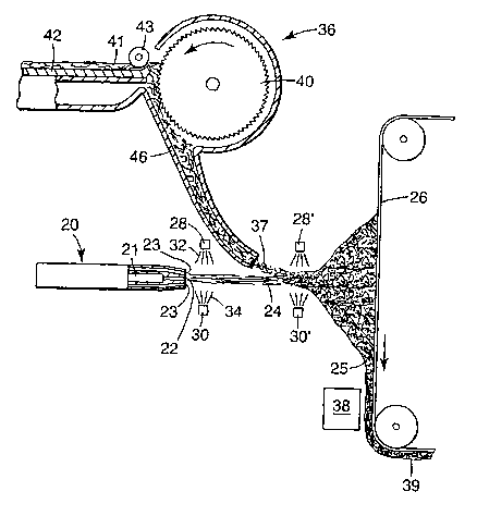
FIGS. 1 and 2 illustrate one embodiment of producing an electret web that
contains
melt-blown fiber. Die 20 has an extrusion chamber 21 through which liquefied
fiber
s forming material is advanced until it exits the die through an orifice 22.
Cooperating gas
orifices 23 - through which a gaseous stream, typically heated air, is forced
at high
velocity - are positioned proximate die orifice 22 to assist in drawing the
fiber-forming
material through the orifice 22. For most commercial applications, a multitude
of die
orifices 22 are arranged in-line across the forward end of the die 20. As the
fiber-forming
material is advanced, a multitude of fibers are emitted from the die face and
collect as a
web 25 on a collector 26. The orifice 22 is arranged to direct the free-
fibers) 24 toward
the collector 26. The fiber-forming material tends to solidify in the interval
between the die
and the collector 26. U.S. Patent 4,118,531 to Hauser and U.S. Patent
4,215,682 to
Kubik and Davis describe a melt-blowing apparatus that employs technology of
this kind.
15 As the fiber-forming material is extruded from the die 20, the gaseous
stream draws
out one or more continuous free-fibers 24. As the length of the free-fiber 24
increases, the
gaseous stream may attenuate or break-oiI'the end of the free-fiber 24. The
broken piece
of free-fiber is carried in the gaseous stream to the collector 26. The
process parameters
for forming the free-fiber 24 may be varied to alter the fiber-breaking
location. For
20 example, reducing the cross-sectional fiber diameter, or increasing the gas
stream velocity,
generally causes the fiber to break closer to the die 20.
To maximize the electric charge in a nonwoven web, the fibers preferably are
not
substantially entangled during the spraying step. Spraying is most efi'ective
when
performed before the free-fibers 24 become entangled. Entangled fibers overlap
and may
prevent some of the fibers from being exposed to the polar liquid spray and
may thus
reduce the resulting electric charge. In applications where multiple fibers 24
are formed
simultaneously, the polar liquid spray could entangle the fibers and thereby
prevent some of
the fibers from being sprayed with the polar liquid. Additionally, the fibers
24 would likely
be driven off course by the force of the polar liquid spray, making it more
difficult to
collect the fibers.
-9-
CA 02385788 2002-03-21
WO 01/27371 PCT/US00/01973
The gaseous stream controls fiber movement during transit to the collector 26.
As
the fiber 24 leaves the orifice 22, the distal end of the fiber 24 is free to
move and become
entangled with adjacent fibers. The proximal end of the fiber 24, however, is
continuously
engaged with the orifice 22, minimizing entanglement immediately in front of
the die 20.
Consequently, spraying is preferably performed close to the die orifice 22.
When a high-velocity gaseous stream is not used, such as in a spun-bond
process, a
continuous free-fiber is typically deposited on the collector. After
collection, the
continuous free-fiber is entangled to form a web by a variety of processes
known in the art,
including embossing and hydroentanglement. Spraying a continuous spun-bond
fiber
stream near the collector promotes entanglement since the distal end of the
fiber is more
easily moved by the force of the polar liquid spray.
In FIG. 2, an upper spraying mechanism 28 is shown located above a center line
c
of the orifice 22 at a distance e. The spraying mechanism 28 is also located
downstream
from the tip of the die orifice 22 at a distance d. A lower spraying mechanism
30 is located
below a center line c of the orifice 22 at a distance f and is located
downstream from the tip
of the die orifice 22 at a distance g. The upper and lower spraying mechanisms
28, 30 are
positioned to emit a spray 32, 34 of a polar liquid onto the stream of free-
fibers 24.
The spraying mechanisms 28, 30 may be used separately or simultaneously from
multiple sides. The spraying mechanisms 28, 30 may be used to spray a vapor of
polar
liquid such as steam, an atomized spray or mist of fine polar liquid droplets,
or an
intermittent or continuous steady stream of a polar liquid. In general, the
spraying step
involves contacting the free fiber with the polar liquid by having the polar
liquid supported
by or directed through a gas phase in any of the forms just described. The
spraying
mechanisms 28, 30 may be located essentially anywhere between the die 20 and
the
collector 26. For example, in an alternate embodiment shown in FIG. 1,
spraying
mechanisms 28', 30' are located closer to the collector and even downstream to
a source
36 that supplies staple fibers 37 to the web 25.
Spraying the free-fibers while they are in a molten state or in a semi-molten
state
has been found to maximize the imparted charge. The spraying mechanisms 28, 30
are
preferably located as close to the stream of free-fibers 24 as possible
(distances a and f are
minimized), without interfering with the flow of free-fibers 24 to the
collector 26. The
-10-
W~ 01/27371 CA 02385788 2002-03-21 pCT/US00/01973
distances a and f are preferably about 30.5 cm (one foot) or less, more
preferably less than
15 cm (6 inches), laterally from the free fiber. The polar liquid may be
sprayed
perpendicular to the stream of free-fibers or at an acute angle, such as at an
acute angle in
the general direction of free-fiber movement.
As indicated, the spraying mechanisms 28, 30 are preferably located as close
to the
tip of the die 20 as possible (distances d and g are minimized). Physical
constraints
typically prevent locating the spraying mechanisms 28, 30 closer than about
2.5 cm (1.0
inch) to the tip of the die 20, although it may be possible to locate the
spraying mechanisms
28, 30 closer to the die 20 if desired, for example, by using specialized
equipment. The
maximum distance the spraying mechanisms 28, 30 can be located from the tip of
the die 20
(distances d and g) is dependent upon the process parameters, since spraying
should occur
before the fibers become entangled. Typically, distances d and g are less than
20 cm (6
inches).
The polar liquid is sprayed on the fibers in quantities sufficient to
constitute an
"effective amount." That is, the polar liquid is contacted with the free-
fibers in an amount
sufficient to enable an electret to be produced using the process of the
invention. Typically,
the quantity of polar liquid used is so great that the web is wet when
initially formed on the
collector. It may be possible, however, for no water to be present on the
collector if, for
example, the distance between the origin of the free-fiber and the collector
is so great that
the polar liquid dries while on the free-fiber rather than while on the
collected web. In a
preferred embodiment of the invention, however, the distance between the
origin and
collector are not so Beat, and the polar liquid is employed in such amounts
that the
collected web is wet with the polar liquid. More preferably, the web is so wet
that the web
will drip when slight pressure is applied. Still more preferably, the web is
substantially or
completely saturated with the polar liquid at the point where the web is
formed on the
collector. The web may be so saturated that the polar liquid regularly drips
from the web
without any pressure being applied.
The amount of polar liquid that is sprayed on the web may vary depending on
the
fiber production rates. If fiber is being produced at a relatively slow rate,
lower pressures
may be used because there is more time for the fiber to adequately contact the
polar liquid.
Thus, the polar liquid may be sprayed at a pressure of about 30 kilopascals
(kPa) or greater.
-11-
WO 01/27371 CA 02385788 2002-03-21 pCT/US00/01973
For faster fiber production rates, the polar liquid generally needs to be
sprayed at greater
throughputs. For example, in a melt-blowing process, the polar liquid
preferably is applied
at a pressure of 400 kilopascals or greater, more preferably at 500 to 800
kilopascals or
Beater. Higher pressures can generally impart better charge to the web, but
too high a
pressure may interfere with fiber formation. Thus, the pressure is typically
kept below 3,500
kPa, more typically below 1,000 kPa.
Water is a preferred polar liquid because it is inexpensive. Also, no
dangerous or
harmful vapors are generated when it contacts the molten or semi-molten fiber-
forming
material. Preferably purified water, made through, for example, distillation,
reverse osmosis,
or deionization, is used in the present invention rather than simply tap
water. Purified water
is preferred because non-pure water can hinder effective fiber charging. Water
has a dipole
moment of about 1.85 Debye and has a dielectric constant of about 78-80.
Aqueous or nonaqueous polar liquids may be used in place of, or in conjunction
with
water. An "aqueous liquid" is a liquid that contains at least 50 volume
percent water. A
"nonaqueous liquid" is a liquid that contains less than 50 volume percent
water. Examples
of nonaqueous polar liquids that may be suitable for use in charging fibers
include methanol,
ethylene glycol, dimethyl sulfoxide, dimethylforrnamide, acetonitrile, and
acetone, among
others, or combinations of these liquids. The aqueous and nonaqueous polar
liquids require
a dipole moment of at least 0.5 Debye, and preferably at least 0.75 Debye, and
more
preferably at least 1.0 Debye. The dielectric constant is at least 10,
preferably at least 20,
and more preferably at least 50. The polar liquid should not leave a
conductive, non-volatile
residue that would mask or dissipate the charge on the resulting web. In
general, it has been
found that there tends to be a correlation between the dielectric constant of
the polar liquid
and the filtration performance of the electret web. Polar liquids that have a
higher dielectric
constant tend to show greater filtration-performance enhancement.
For filtration applications, the nonwoven web preferably has a basis weight
less than
about 500 grams/meter2 (g/m2), more preferably about 5 to about 400 m2, and
still more
preferably about 20 to 100 glm2. In making melt-blown fiber webs, the basis
weight can be
controlled, for example, by changing either die throughput or collector speed.
The thickness
of the nonwoven web for many filtration applications is about 0.25 to about 20
millimeters
(mm), more typically about 0.5 to about 4 mm. The solidity of the resulting
nonwoven web
-12-
CA 02385788 2002-03-21
WO 01/27371 PCT/US00/01973
preferably is at least 0.03, more preferably about 0.04 to 0.15, and still
more preferably
about 0.05 to 0.1. Solidity is a unitless parameter that defines the solids
fraction in the web.
The inventive method can impart a generally uniform charge distribution
throughout the
resulting nonwoven web, without regard to basis weight, thickness, or solidity
of the
resulting media.
The collector 26 is located opposite the die 20 and typically collects wet
fibers 24.
The fibers 24 become entangled either on the collector 26 or immediately
before impacting
the collector. As indicated above, the fibers when collected are preferably
damp, and more
preferably are substantially wetted, and still more preferably are filled
essentially to capacity
or are substantially saturated with the polar liquid. The collector 26
preferably includes a
web transport mechanism that moves the collected web toward a drying mechanism
38 as
the fibers 24 are collected. In a preferred process, the collector moves
continuously about
an endless path so that electret webs can be manufactured continuously. The
collector may
be in the form of, for example, a drum, belt, or screen. Essentially any
apparatus or
operation suitable for collecting the fiber is contemplated for use in
connection with the
present invention. An example of a collector that may be suitable is described
in U.S. Patent
Application Serial No. 09/181,205 entitled Uniform Meltblawn Fibrous Web And
Method
And Apparatus For Manufacturing.
The drying mechanism 38 is shown located downstream from where the fibers 24
are
collected - although it may be possible to dry the fibers before being
collected (or both
before and after being collected) to produce an electret web in accordance
with the present
invention. The drying mechanism may be an active drying mechanism, such as a
heat
source, a flow-through oven, a vacuum source, an air source such as a
connective air
source, a roller to squeeze the polar liquid from the web 25, or a combination
of such
devices. Alternatively, a passive drying mechanism - air drying at ambient
temperatures -
may be used to dry the web 25. Ambient air drying, however, may not be
generally practical
for high speed manufacturing operations. Essentially any device or operation
suitable for
drying the fibers and/or web is contemplated for use in this invention; unless
the devices or
operations were to somehow adversely impact the production of an electret.
After drying,
the resulting charged electret web 39 can then be cut into sheets, rolled for
storage, or
formed into various articles, such as filters for respirators.
-13-
CA 02385788 2002-03-21
WO 01/27371 PCT/US00/01973
The resulting charged electret web 39 may also be subjected to further
charging
techniques that might further enhance the electret charge on the web or might
perform some
other alteration to the electret charge that could possibly improve filtration
performance.
For example, the nonwoven fibrous electret web could be exposed to a corona
charging
operation after producing the electret product using the process described
above. The web
could be charged, for example, as described in U.S. Patent 4,588,537 to Klaase
et al., or as
described in U.S. Patent 4,592,815 to Nakao. Alternatively - or in conjunction
with the
noted charging techniques - the web could also be further hydrocharged as
described in
U.S. Patent 5,496,507 to Angadjivand et al.
The charge of the fibrous electret web may also be supplemented using other
charging techniques, such disclosed in the commonly assigned U.S. Patent
applications
entitled Method and Apparatus for Making a Fibrous Electret Web Using a
Wetting Liquid
and an Aqueous Polar Liquid (LT.S. Serial No. 09/415,291); and Method of
Making a
Fibrous Electret Web Using a Nonaqueous Polar Liquid (CT. S. Serial No.
09/416,216); all
filed on the same day as the present case.
As shown in FIG. 1, staple fibers 37 may be combined with the free-fibers 24
to
provide a more lofty, less dense web. "Staple fibers" are fibers that are cut
or otherwise
made to a defined length, typically of about 2.54 cm ( 1 inch) to about 12.7
cm (5 inches).
The staple fibers typically have a denier of 1 to 100. Reducing the web
density 25 may be
beneficial to reduce pressure drop across the web 25, which may be desirable
for some
filtering applications, such as in personal respirators. Once entrapped within
the stream of
free-fibers 24, the staple fibers 37 are sufficiently supported in the web and
may also be
charged by a polar liquid spray, such as by spraying mechanisms 28', 30',
along with the
free-fibers 24.
Staple fibers 37 may be introduced to the web 25 through use of a lickerin
roll 40
disposed above the fiber blowing apparatus as shown in FIG. 1 (see also U. S.
Patent
4,118,531 to Hauser). A web 41 of fibers, typically a loose, nonwoven web
prepared, for
example, using a garnet or RANDO-WEBBER apparatus (available from Rando
Machine
Corp. of Rochester, New York), is propelled along table 42 under drive roll 43
where the
leading edge engages against the lickerin roll 40. The lickerin roll 40 picks
off fibers from
the leading edge of web 41 to create the staple fibers 37. The staple fibers
37 are conveyed
- 14-
WO 01/27371 CA 02385788 2002-03-21 pCT~S00/01973
in an air stream through an inclined trough or duct 46 into the stream of
blown fibers 24
where the staple and blown fibers become mixed. Other particulate matter may
be
introduced into the web 25 using a loading mechanism similar to duct 46.
Typically, no
more than about 90 weight percent staple fibers 37 are present, and more
typically no more
than about 70 weight percent.
Active particulate also may be included in the electret webs for various
purposes,
including sorbent purposes, catalytic purposes, and others. U.S. Patent
5,696,199 to
Senkus et al., for example, describes various active particulate that may be
suitable. Active
particulate that has sorptive properties - such as activated carbon or alumina
- may be
included in the web to remove organic vapors during filtration operations. The
particulate
may be present in general in amounts up to about 80 volume percent of the
contents of the
web. Particle-loaded nonwoven webs are described, for example, in U.S. Patents
3,971,373 to Braun, 4,100,324 to Anderson, and 4,429,001 to Kolpin et al.
Polymers, which may be suitable for use in producing fibers that are useful in
this
invention, include thermoplastic organic nonconductive polymers. The polymers
can be
synthetically produced organic macromolecules that consist essentially of
recurnng long
chain structural units made from a large number of monomers. The polymers used
should
be capable of retaining a high quantity of trapped charge and should be
capable of being
processed into fibers, such as through a melt-blowing apparatus or a spun-
bonding
apparatus. The term "organic" means the backbone of the polymer includes
carbon atoms.
The term "thermoplastic" refers to a polymeric material that softens when
exposed to heat.
Preferred polymers include polyolefins, such as polypropylene, poly-4-methyl-1-
pentene,
blends or copolymers containing one or more of these polymers, and
combinations of these
polymers. Other polymers may include polyethylene, other polyolefins,
polyvinylchlorides,
polystyrenes, polycarbonates, polyethylene terephthalate, other polyesters,
and
combinations of these polymers and other nonconductive polymers. The free-
fibers may be
made from these polymers in conjunction with other suitable additives. The
free-fibers may
be extruded or otherwise formed to have multiple polymer components. See U. S.
Patent
4,729,371 to Krueger and Dyrud and U.S. Patents 4,795,668, and 4,547,420 to
Krueger
and Meyer. The different polymer components may be arranged concentrically or
longitudinally along the length of the fiber in the form of, for example,
bicomponent fibers.
-15-
CA 02385788 2002-03-21
WO 01/27371 PCT/US00/01973
The fibers may be arranged to form a macroscopically homogeneous web, which is
a web
that is made from fibers that each have the same general composition.
The fibers used in the invention do not need to contain ionomers, particularly
metal
ion neutralized copolymers of ethylene and acrylic or methacrylic acid or both
to produce a
fibrous product suitable for filtration applications. Nonwoven fibrous
electret webs can be
suitably produced from the polymers described above without containing 5 to 25
weight
percent (meth)acrylic acid with acid groups partially neutralized with metal
ions.
For filtering applications, the fibers preferably are microfibers that have an
effective
fiber diameter less than 20 micrometers, and more preferably about 1 to about
10
micrometers, as calculated according to the method set forth in Davies, C.N.,
The
Separation of Airborne Dust and Particles, Institution of Mechanical
Engineers, London,
Proceedings 1B (1952), particularly equation number 12.
The performance of the electret web can be enhanced by including additives in
the
fiber-forming material before contacting it to a polar liquid. Preferably, an
"oily-mist
performance enhancing additive" is used in conjunction with the fibers or the
fiber-forming
materials. An "oily-mist performance enhancing additive" is a component which,
when
added to the fiber-forming material, or for example, is placed on the
resulting fiber, is
capable of enhancing the oily aerosol filtering ability of the nonwoven
fibrous electret web.
Fluorochemicals can be added to the polymeric material to enhance electret
performance. U.S. Patents 5,411,576 and 5,472,481 to Jones et al. describe the
use of a
melt-processable fluorochemical additive that has a melt temperature of at
least 25 °C and
that has a molecular weight of about 500 to 2500. This fluorochemical additive
may be
employed to provide better oily mist resistance. One additive class that is
known to
enhance electrets that have been charged with water jets are compounds that
have a
perfluorinated moiety and a fluorine content of at least 18% by weight of the
additive -
see U.S. Patent 5,908,598 to Rousseau et al. An additive of this type is a
fluorochemical
oxazolidinone described in U.S. Patent 5,411,576 as "Additive A" of at least
0.1 % by
weight of the thermoplastic material.
Other possible additives are thermally stable organic triazine compounds or
oligomers, which compounds or oligomers contain at least one nitrogen atom in
addition to
those in the triazine ring. Another additive known to enhance electrets
charged by jets of
- 16-
W~ ~l/27371 CA 02385788 2002-03-21 pCT/US00/01973
water is ChimassorbTM 944 LF (poly[[6-(1,1,3,3,-tetramethylbutyl) amino]-s-
triazine-2,4-
diyl][[(2,2,6,6-tetramethyl-4-piperidyl) imino] hexamethylene [(2,2,6,6-
tetramethyl-4-
piperidyl) imino]]), available from Ciba-Geigy Corp. Chimassorb't'M 944 and
"Additive A"
may be combined. Preferably the additive ChimassorbTM and/or the above
additives are
present in an amount of about 0.1% to about 5% by weight of the polymer; more
preferably, the additives) is present in an amount from about 0.2% to about 2%
by weight
of the polymer; and still more preferably is present in an amount from about
0.2 to about 1
weight % of the polymer. Some other hindered amines are also known to increase
the
filtration-enhancing charge imparted to the web. If the additive is heat
sensitive, it may be
introduced into the die 20 from a smaller side extruder immediately upstream
to the orifice
22 in order to minimize the time it is exposed to elevated temperatures.
Fibers that contain additives can be quenched after shaping a heated molten
blend of
the polymer and additive - followed by annealing and charging steps - to
create an
electret article. Enhanced filtration performance can be imparted to the
article by making
the electret in this manner - see U.S. Patent Application Serial No.
08/941,864, which
corresponds to International Publication WO 99/16533. Additives also may be
placed on
the web after its formation by, for example, using the surface fluorination
technique
described in U.S. Patent Application 09/109,497, filed July 2, 1998 by Jones
et al.
The polymeric fiber-forming material has a volume resistivity of 1014 ohm~cm
or
Beater at room temperature. Preferably, the volume resistivity is about 1016
ohm~cm or
greater. Resistivity of the polymeric fiber-forming material can be measured
according to
standardized test ASTM D 257-93. The fiber-forming material used to form the
melt
blown fibers also should be substantially free from components such as
antistatic agents
that could increase the electrical conductivity or otherwise interfere with
the fiber's ability
to accept and hold electrostatic charges.
Nonwoven webs of this invention may be used in filtering masks that are
adapted to
cover at least the nose and mouth of a wearer.
FIG. 3 illustrates a filtering face mask 50 that may be constructed to contain
an
electrically-charged nonwoven web produced according to the present invention.
The
generally cup-shaped body portion 52 is adapted to fit over the mouth and nose
of the
wearer. A strap or harness system 52 may be provided to support the mask on
the wearer's
- 17-
WO 01/27371 CA 02385788 2002-03-21 pCT~S00/01973
face. Although a single strap 54 is illustrated in FIG. 3, the harness may
come in a variety of
configurations; see, for example, U.S. Patent 4,827,924 to Japuntich et al.,
5,237,986 to
Seppalla et al., and 5,464,010 to Byram. Examples of other filtering face
masks where
nonwoven webs of the invention may be used include U.S. Patents 4,536,440 to
Berg;
4,807,619 to Dyrud et al.; 4,883,547 to Japuntich; 5,307,796 to Kronzer et
al.; and
5,374,458 to Burgio. The present electret filter media also may be used in a
filter cartridge
for a respirator, such as in the filter cartridge disclosed in U.S. Patent No.
Re. 35,062 to
Brostrom et al. or U.S. Patent 5,062,421 to Burns and Reischel. Mask 50 thus
is presented
for illustration purposes only, and use of the present electret filter media
is not limited to the
embodiment disclosed.
Applicants believe that the present charging method deposits both positive and
negative charge onto the fibers such that the positive and negative charge is
randomly
dispersed throughout the web. Random charge dispersal produces an unpolarized
web.
Thus, a nonwoven fibrous electret web produced in accordance with the present
invention
may be substantially unpolarized in a plane normal to the plane of the web.
Fibers that have
been charged in this manner ideally exhibit the charge configuration shown in
Figures SC of
U.S. Patent Application Serial No. 08/865,362. If the fibrous web is also
subjected to a
corona charging operation, it would exhibit a charge configuration similar to
the
configuration shown in Figure SB of that patent application. A web, formed
from fibers
charged solely using the present method, typically has unpolarized trapped
charge
throughout the volume of the web. "Unpolarized trapped charge" refers to a
fibrous
electret web that exhibits less than 1 pC/m2 of detectable discharge current
using TSDC
analysis, where the denominator is the electrode surface area. This charge
configuration
can be shown by subjecting the web to thermally-simulated discharge current
(TSDC).
Thermally-stimulated discharge analysis involves heating an electret web so
that the
frozen or trapped charge regains mobility and moves to some lower energy
configuration to
generate a detectable external discharge current. For a discussion on
thermally-stimulated
discharge current, see Lavergne et al., A review of Thermo-Stimulated Current,
IEEE
ELECTIUCAL INSULATION MAGAZINE, vol. 9, no. 2, S-21, 1993, and Chen et al.,
Analysis of
Thermally Stimulated Process, Pergamon Press, 1981.
-18-
CA 02385788 2002-03-21
WO 01/27371 PCT/US00/01973
An electric charge polarization can be induced in a web that has been charged
according to the present invention by elevating the temperature to some level
above the
glass transition temperature (T~ of the polymer, which is the temperature
where a polymer
changes to a viscous or rubbery condition from a hard and relatively-brittle
one. The glass-
y transition temperature, T~, is below the polymer's melting point (Tm). After
raising the
polymer above its Tg, the sample is cooled in the presence of an electric
field to freeze-in
the polarization of the trapped charge. Thermally-stimulated discharge
currents can then be
measured by reheating the electret material at a constant heating rate and
measuring the
current generated in an external circuit. An instrument useful for performing
the
polarization and subsequent thermally-stimulated discharge is a Solomat
TSC/RMA model
91000 with a pivot electrode, distributed by TherMold Partners, L.P., Thermal
Analysis
Instruments of Stamford, Connecticut.
The discharge current is plotted on the y axis (ordinate) against the
temperature on
the x axis (abscissa). The peak (current maximum) position and shape of the
discharge
current are characteristics of the mechanism by which the charges have been
stored in the
electret web. For electret webs that contain a charge, the peak maximum and
shape are
related to the configuration of the charge trapped in the electret material.
The amount of
charge produced in the outside circuit due to movement of the charge inside
the electret
web to a lower energy state upon heating can be determined by integrating the
discharge
peak(s).
Advantages and other properties and details of this invention are further
illustrated
in the following Examples. It is to be expressly understood, however, that
while the
examples serve this purpose, the particular ingredients and amounts used and
other
conditions are not to be construed in a manner that would unduly limit the
scope of this
invention. The Examples selected for disclosure are merely illustrative of how
to make a
preferred embodiment of the invention and how the articles can generally
perform.
EXAMPLES
Sample Preparation
Fibers were prepared generally as described by Van A. Wente, 48 INDUS. ~m
ENGN. C~lvt., 1342-46 (1956), modified to include one or two atomizing spray
bars
-19-
WO 01/27371 CA 02385788 2002-03-21 pCT~S00/01973
mounted downstream from the die tip to spray a polar liquid on the fibers
after extrusion
and before collection. The resin was FINA 3860X thermoplastic polypropylene
(available
from Fina Oil and Chemical Co.) unless otherwise specified. The extruder was a
Berstorff
60 millimeter, 44 to 1, eight barrel zone, co-rotating twin screw extruder
available from
Berstorff Corp. of Charlotte, North Carolina. When an additive was
incorporated in the
resin, it was prepared as a 10-15 weight percent concentrate in a Werner
Pfleiderer 30 mm,
36 to 1 co-rotating twin screw extruder available from Werner & Pfeiderer
Corp. of
Ramsey, New Jersey. The polar liquid was water purified by reverse osmosis and
deionization. The basis weight of the resulting web was about 54-60
grams/meter2, unless
otherwise specified.
DOP Penetration and Pressure Drop Test
The following summary of DOP penetration and pressure drop applies to Examples
1-30 and to the Initial Quality Factor references in the definitions set forth
above and in the
claims. The DOP Penetration and Pressure Drop Test was performed by forcing
dioctyl
phthalate (DOP) 0.3 micrometer mass median diameter particles through a sample
of the
nonwoven web that was 11.45 cm (4.5 inches) in diameter at a rate of 32
liters/minute
(L/min). The face velocity on the sample was 5.2 centimeters per second. The
DOP
particles were at a concentration of between about 70 and about 110
milligrams/meter3.
The samples were exposed to the aerosol of DOP particles for 30 seconds. DOP
particle
penetration through the samples was measured using a model TSI 8110 Automated
Filter
Tester available from TSI of St. Paul, Minnesota. The pressure drop (DP)
across the
sample was measured using an electronic manometer and was reported in
millimeters of
water.
The DOP penetration and pressure drop values were used to calculate quality
factor, QF, from the natural log (1n) of the DOP penetration using the
following formula:
QF [1/mm H20] _ -(ln ((DOP Pen %)/100))/ Pressure Drop [mm H20].
The higher the QF value, the better the filtration performance.
All samples tested below were tested for an Initial Quality Factor, QF;.
-20-
CA 02385788 2002-03-21
WO 01/27371 PCT/US00/01973
Alternate DOP Penetration and Pressure Drop Test
An alternate DOP pressure drop test was utilized for Example 31 only. This
test
applies only to this Example. The alternate procedure was performed generally
according
to the procedure outlined above, except that the dioctyl phthalate (DOP) 0.3
micrometer
mass median diameter particles at a concentration of between 70 and 110 mg/m3
were
generated using a TSI No. 212 sprayer with four orifices and 207 kPa (30 psi)
clean air.
DOP particles were forced through the sample of nonwoven web at a rate of 42.5
L/min,
with a resulting face velocity of 6.9 cm/sec. The penetration was measured
using an optical
scattering chamber, Percent Penetration Meter Model TPA-8F available from Air
Techniques Inc. of Baltimore, Maryland. The quality factor is calculated as
discussed
above. At this higher face velocity, the quality factor values will be
somewhat lower than
at the lower face velocity.
Examples 1-2 and Comparative Example C1
The following examples show the beneficial effect of spraying water on the
free-
fibers to increase quality factor. Samples of Examples 1-2 and Comparative
Example C1
all contained ChimassorbTM 944 at a concentration of 0.5 weight percent, to
enhance the
charging. The sample of Example 1 was made using a single-air atomizing spray
bar that
had 6 individual spray nozzles mounted about 17.8 cm (7 inches) below the die
center line
and about 5.08 cm (2 inches) downsteam of the die tip. The spray bar was a
model 1/4J
available from Spraying Systems of Wheaton, Illinois. Each spray nozzle had a
fluid cap
(model no. 2850) and an air cap (model no. 73320) for atomizing the water,
both available
from Spraying Systems. The water pressure in the sprayer was about 344.7 kPa
(50 psi),
and the air pressure in the sprayer was about 344.7 kPa (SO psi). Water was
sprayed on the
fibers in an amount sufficient to substantially wet the collected web. The
collector was
positioned about 35.6 cm (14 inches) downstream from the end of the die. The
water was
removed from the collected web by drying it in a batch oven at about 54.5
°C (130 °F).
The sample of Example 2 was sprayed using two air-atomizing spray bars. The
spray bar of Example 1 was used as the top spray bar. The top spray bar was
mounted
about 17.8 cm (7 inches) above the die center line, and the bottom spray bar
was mounted
about 17.8 cm (7 inches) below the die center line. The bottom spray bar was
an atomizing
-21 -
CA 02385788 2002-03-21
WO 01/27371 PCT/US00/01973
sonic spray system with 15 model no. SDC 035H spray nozzles, available from
Sonic
Environmental Corp. of Pennsauken, NJ. Both spray bars were located about 5.08
cm (2
inches) downstream from the die tip. The water and air pressure on each bar
were about
344.7 kPa (50 psi). The web was wetted substantially more than the web of
Example 1.
The water was removed by drying the collected web in a batch oven at about
54.5 °C (130
°F). Comparative Example C 1 is the same as Example 1 or 2 but without
water spray. The
results are given in Table 1.
Table 1
Effect of Water Spray on Free-fibers
Example Spray BarsPressure PenetrationQF~
Drop (%) (mm H20)-1
mm water
1 One 1.2 15.64 1.55
2 Two 1.56 5.86 1.82
C 1 None 1.76 76.1 0.16
The data of Table 1 show that spraying the free-fibers with an effective
amount of
water after extrusion and before collection increases QF; significantly, which
indicates an
1 S improved ability of the collected web to filter particles from an air
stream. The results also
show that two spray bars may be more effective than one.
Examples 3-4
The following examples show the beneficial effect on QF; using ChimassorbTM
944
as an additive to the polymer. The concentration of ChimassorbTM 944 is shown
in Table 2
as a weight percentage of the polymer. The water spray was carried out as
described for
Example 1 except that the water pressure on the fluid cap was about 138 kPa
(20 psi), and
the air pressure on the air cap was about 414 kPa (60 psi). The reduction in
water pressure
reduced the total volume of water on the web to less than Example 1. Heat from
the fibers
caused a portion of the water to evaporate before collection so that the
collected nonwoven
web was only damp.
Water was removed from the samples of Examples 3-4 by oven drying. The oven
contained two perforated drums. Heated air is drawn through the web. The
residence time
-22-
CA 02385788 2002-03-21
WO 01/27371 PCT/US00/01973
of the web in the oven was about 1.2 minutes at an air temperature of about
71.1 °C
(160 °F). Ovens of this type are available from Aztec Machinery Co. of
Ivyland,
Pennsylvania. The results are given in Table 2.
S Table 2
Effect of CbimassorbTM 944 Additive
Ezample C6imaasorb Pressure Penetration
Cone. (Wt%) Drop (%) mm HZU
(mm water) -1
3 0.0 1.5 66.1 0.28
4 0.5 1.8 47.0 0.42
The data of Table 2 demonstrate an improvement in QF; realized by adding
ChimmassorbTM 944 to the thermoplastic material. The use of a lower water
pressure
deposits less water on the fibers and may reduce product performance as
measured by QF;
discussed further in examples 5-9 below.
Examples 5-9
The following examples show the effect of water pressure on quality factor.
The
spraying was earned out as described in Example 1 with a spray bar having a
fluid cap and
an air cap to atomize the polar liquid. The air pressure on the air cap was
about 414 kPa
(60 psi). The fluid pressure on the fluid cap is shown in Table 3.
ChimassorbTM 944 was present at about 0.5 weight percent based on the weight
of
polymer. Water was removed by oven drying as discussed in Examples 3-4. Excess
water
was removed from the web of Examples 8-9 by vacuuming the water before oven
drying.
Vacuuming was performed by passing the web over a vacuum bar having a vacuum
slot in
fluid communication with a vacuum chamber. The vacuum slots were about 6.35 mm
(0.25
inches) wide and about 114.3 cm (45 inches) long. In Example 8, a single
vacuum slot was
used. In Example 9, two vacuum slots were used. The pressure drop across the
slot as the
web moves past was about 7.5 kPa (30 inches of water). The results are given
in Table 3.
- 23 -
W~ 01/27371 CA 02385788 2002-03-21 pCT~S00/01973
Table 3
Effect of Water Pressure
Ezample Water PressurePressure Penetration
Drop (%) (mm H20)-1
mm water
138 kPa 20 1.8 47.0 0.42
si
6 414 kPa 60 2.2 27.5 0.59
si
7 552 kPa (80 1.7 19.6 0.96
psi)
8* 552 kPa (80 2.1 9.4 1.12
psi)
9* 552 kPa (80 2.0 9.18 1.19
psi)
*Samples were vacuumed before oven drying
5
The data in Table 3 show that increasing the water pressure results in an
increased
QF;. Examples 8 and 9 show that removal of excess water before drying the web
can
increase QF;.
Examples 10-17
The following examples show an improved quality factor over the Examples in
Table 3 by removing the air caps from the spray nozzles. The air caps atomize
the water.
Removing the air caps allows a stream of large water droplets to directly
impact the molten
polymer or fibers as they exit the die. The spray bar was moved to about 2.54
cm ( 1 inch)
downstream of the die. ChimassorbTM 944 was present at about 0.5 weight
percent based
on the weight of the polymer. Use of the vacuum source of Example 8 is
indicated in Table
4. Water was removed by oven drying as discussed in Examples 3-4.
-24-
CA 02385788 2002-03-21
WO 01/27371 PCT/US00/01973
Table 4
Resonator Caps Removed
Ezampk Water PressurePressure PenetrationQgi Vacuum
Drop (%)
mm water
276 kPa (40 1.8 21.7 0.85 Yes
psi)
11 276 kPa (40 1.9 17.9 0.91 No
psi)
12 414 kPa (60 2.0 20.1 0.80 No
psi)
13 414 kPa (60 1.9 18.4 0.89 Yes
psi)
14 552 kPa (80 1.8 13.6 1.11 No
psi)
552 kPa (80 1.9 12.8 1.08 Yes
psi)
16 689.41cPa 1.8 11.0 1.23 No
(100 psi)
17 689.41cPa 2.0 9.5 1.18 Yes
(100 psi)
5 The data of Table 4 show an increase in QF; when larger drops of water are
allowed
to impact on the fibers, compared with the results in Table 3 when the air
caps are on.
When the air caps are removed, however, any improvement in QF; due to
vacuuming was
reduced on all samples, except the samples of Examples 12 and 13.
10 Examples 18-22
The following examples show the effect of web basis weight on QF;. The samples
were sprayed with the spray bar configuration of Example 1. The water pressure
on the
fluid cap was about 414 kPa (60 psi), and the air pressure on the air cap was
about 276 kPa
(40 psi). Water was removed by oven drying as discussed in Examples 3-4.
ChimassorbTM
15 944 was present at about 0.5 weight percent based on the weight of the
polymer. Basis
weight is given in grams per square meter. The results are given in Table 5.
- ZS -
WO 01/27371 CA 02385788 2002-03-21 pCT~S00/01973
Table 5
Effect of Basis Weight
Example Water Basis ThicknessPressure PenetrationQF~
add on Wt. (mm) Drop (%) (mm g2p)u
/. (grams/mi) mm water
18 59'/0 25 0.51 0.69 21.4 2.24
19 130'/0 50 0.94 1.81 4.5 1.71
20 134% 100 1.7 2.82 0.8 1.71
21 131% 150 2.6 3.79 0.1 1.85
_
22- - - 143% - --200 3.3 - 5.21 I 0.025 1.59 -
r I ~ -
The data in Table 5 show that QFi for basis weights ranging from about 50
grams/meter2 to about 150 grams/meter2 appear to be similar. QFi seems to drop
off at a
basis weight of about 200 grams/meter2 and increase at a basis weight of about
25
grams/meter2. This apparent result might be due to the pressure drop at high
and low basis
weights.
Examples 23-25
The following examples show the effect of effective fiber diameter (EFD) on
QF;.
The spray bar was configured as described in Examples 18-22. The water
pressure was
about 60 psi, and the air pressure was about 40 psi. Water was removed by oven
drying as
discussed in Examples 3-4. ChimassorbTM 944 was present at a level of about
0.5 weight
percent. The EFD is given in micrometers. The results are given in Table 6.
Table 6
Effect of Effective Fiber Diameter (EFD)
Example E~ Pressure PenetrationQF~
(micrometers)Drop (%) mm H2U 1
(mm water)
23 8 1.81 17 1.71
24 10 1.51 4.4 2.07
12 1.25 7.3 2.10
The data in Table 6 show that QF; increases with increased effective fiber
diameter.
-26-
CA 02385788 2002-03-21
WO 01/27371 PCT/US00/01973
Examples 26-27
The following examples show the effect of spray bar location on quality
factor. The
samples of these examples had a basis weight of about 57 grams/meter2. The
samples were
sprayed with the spray bar configuration of Example 1. The water pressure on
the fluid cap
was about 414 kPa (60 psi), and the air pressure on the air cap was about 276
kPa (40 psi).
Water was removed by oven drying as discussed in Examples 3-4. The results are
given in
Table 7. The location refers to distances d and g of FIG. 2.
Table 7
Effect of Spray Bar Location
Example Location Pressure PenetrationQFi
(cm) Drop (%) (mm H20)-1
(mm water)
26 15.24 1.54 11.2 1.42
27 5.08 1.59 8.5 1.55
The data of Table 7 show an increase in filter performance when the spray bars
are
located closer to die. The water on the collected web of Example 26 was about
59 weight
percent of the web's weight. The water on the collected web of Example 27 was
about 28
weight percent of the web's weight. The quantity of water on the web of
Example 26 was
greater than the quantity of water on the web of Example 27 due to the
placement of the
spraying bars.
Examples 28-29
The following examples show the effect of using different resins on quality
factor.
Both examples used the spray bar used in Examples 18-22, located about 7.62 cm
(3 inches)
downstream from the die tip. In example 28, the resin was poly 4-methyl-1-
pentene,
available from Mitsui Petrochemical Industries, Tokyo, Japan as TPX-MX002. The
water
pressure was about 241.3 kPa (35 psi), and the air pressure was about 276 kPa
(40 psi).
ChimassorbTM 944 was added by a secondary extruder into the sixth zone of the
main
extruder to give about 0.5 weight percent of the extruded fibers. In example
29, the resin
was a thermoplastic polyester available from Hoechst Celanese as Product No.
2002 (Lot
-27-
CA 02385788 2002-03-21
WO 01/27371 PCT/US00/01973
no. LJ30820501). The water pressure was about 414 lcPa (60 psi), and the air
pressure was
about 206.8 lcPa (30 psi). Chimassorb'''M 944 was added to the main extruder
at about 0.5
weight percent of the extruded fibers. Water was removed by oven drying as
discussed in
Examples 3-4. The results are given in Table 8.
Table 8
Effect of Resin
QF,
Ezsmple Resin Resin Pressure PenetrationBasis (mm
ConductivityDrop (%) Weight Hz0)-'
(mm water) (grams/
meters
28 poly <10-'6 1.60 10 173 1.44
4-
methyl-1-
entene
29 0l esterlO-14~ 1.64 48.9 107 0.44
*estimated
The data of Table 8 show that it is possible under the present invention to
use fibers
made of different nonconductive resins.
Example 30
This example shows that charging additives can be used in the invention. The
additive used to enhance charging in this example is disclosed in Example 22
from U.S.
Patent 5,908,598. In particular, N,N'-di-(cyclohexyl)-hexamethylene-diamine
was prepared
as described in U.S. Patent No. 3,519,603. Next, 2-(tert.-octylamino)-4,6-
dichloro-1,3,5
triazine was prepared as described in U.S. Patent No. 4,297,492. Finally, this
diamine was
reacted with the dichlorotriazine described in U.S. Patent No. 4,492,791
(hereinafter
"triazine compound"). The additive was added at a level of about 0.5 weight
percent of the
thermoplastic material. Other conditions were as substantially described in
Example 1.
Water was removed by oven drying as discussed in Examples 3-4. The results are
given in
Table 9.
-28-
CA 02385788 2002-03-21
WO 01/27371 PCT/LTS00/01973
Table 9
Additive
Ezampk Add'rt'rvePressure PenetrationBasis WeightQFi
Drop
mm water % rams/meterz mm H=O
-'
30 Triazine 1.65 37.1 62 0.60
Compound
The data of Table 9 show that other additives can be used when forming
electret
media of the present invention.
Example 31
An electric charge polarization was induced in the webs of Examples 3 and 30
by
elevating the temperature to 100 °C, poling the sample in the presence
of a DC field of
about E",~ = 2.5 KV/mm at 100 °C for poling periods of about 10, 15 and
20 minutes, and
cooling the sample to -50 °C in the presence of the DC field. The
polarization of the
trapped charge was "frozen-in" the web. Thermally stimulated discharge current
(TSDC)
analysis involves reheating the electret web so that the frozen charge regains
mobility and
moves to some lower energy state, thereby generating a detectable external
discharge
current. Polarization and subsequent thermally stimulated discharge was
performed using a
Solomat TSC/RMA model 91000 with a pivot electrode, distributed by TherMold
Partners,
L.P., Thermal Analysis Instruments of Stanford, Connecticut.
After cooling, the webs were reheated from about -50 °C to about 160
°C at a
heating rate of about 3 °C/minute. The external current generated was
measured as a
function of temperature. The total amount of charge released was obtained by
calculating
the area under the discharging peaks.
-29-
l G-1 G-20~ l ' USUUU~ X73
Table 10.
Measured Charge Density after Polarization ..
f Eiample QF~ Value Charge Poling Time to
Mai.
(mm H=O)''. Density Charge Density
. ~mz
3 0.28 1.87 rox. 13.5 min.
30 0.60 3.50 A rox. 15 min.
_ The data of Table 10 show that webs charged according to the present
invention
have iandomly~ deposited charge when an electric charge polarization is
induced. The
samples were previously examined without subjecting them to poling at an
elevated
temperature. No significant signal was detected when TSDC. was. performed on
those
samples. Because a TSDC was only noticeable after an electric charge
polarization was
induced, the samples are believed to possess an unpolarized trapped charge.
All patents and patent applications cited above, including those cited in the
Background, are incorporated by reference in Total into this document: . .
The present invention may be suitably practiced in the absence of any element
or step
not specifically described in this document.
Changes may be made to the embodiments . described above without departing
from
the scope a~-Spirilt of the invention. The present invention therefore is not
limited to the x
methods and structures described above but only to elements and steps recited
in the claims
and any equivalents to those elements and steps.
-30-
AMENDED SHEET
CA 02385788 2002-03-21