Note: Descriptions are shown in the official language in which they were submitted.
CA 02385825 2002-03-26
WO 01/23847 PCT/US00/26406
LOAD CELL APPARATUS
Background and Summary of the Invention
The present invention relates to load cells and particularly to load cells
that generate signals indicative of loads applied to the load cells. More
particularly
the present invention relates to load cell isolation in load cell systems.
It is well known to use load cells to sense loads. Conventional load
cells typically include a block and one or more strain gages mounted to the
block.
Deflection of the block due to an applied load changes the shape of the strain
gages
resulting in a change in the resistance of the strain gages. Generally, a
known input
voltage is applied to the strain gages and an output signal from the strain
gages varies
as the resistance of the strain gages vary to provide a signal indicative of
the load
applied to the load cell. Load cells are sometimes used in hospital beds as
part of a
weigh system that senses, for example, the weight of a patient supported by
the bed.
It is desirable, of course, for weigh systems to provide accurate weight
readings and
therefore, it is desirable to minimize sources of error that may contribute to
inaccurate
output signals from the load cells.
According to an illustrated embodiment of the present invention, a load
cell apparatus includes a cell block adapted to couple to a first structure, a
mount
adapted to couple to a second structure, and a stud extending from the cell
block. The
mount is made of a first material and is formed to include a bore. The load
cell
apparatus further includes a liner that is positioned to lie in the bore and
that engages
the stud. The liner is made of a second material that is more lubrous than the
first
material.
In one embodiment, the stud extending from the cell block includes a
cylindrical portion and the liner is formed to include a cylindrical cavity
that receives
the cylindrical portion of the stud. In addition, the bore of the mount is
generally
square-shaped and the outer surface of the liner is square-shaped. In this
embodiment,
the liner press fits into the bore of the mount. The liner may include
portions that
protrude from the outer surface thereof to enhance the press fit of the liner
in the bore
of the mount.
In another embodiment, the stud extending from the cell block includes
CA 02385825 2002-03-26
WO 01/23847 PCT/US00/26406
_7_
a cylindrical portion and the liner comprises a pad of material positioned to
lie in the
bore underneath the cylindrical portion of the stud. In yet another
embodiment, the
stud extending from the cell block includes a spherical portion and the liner
comprises
a pad of material positioned to lie in the bore underneath the spherical
portion of the
stud.
In a further embodiment, the stud extending from the cell block
includes a cylindrical portion and the liner coats the stud. In this
embodiment, the
coated stud extends into the bore and engages the mount. In yet another
embodiment,
the stud extending from the cell block includes a spherical portion and the
liner is
formed as an O-ring coupled to the spherical portion.
Additional features and advantages of the invention will become
apparent to those skilled in the art upon consideration of the following
detailed
description of illustrated embodiments exemplifying the best mode of carrying
out the
invention as presently perceived.
Brief Description of the Drawings
The detailed description particularly refers to the accompanying figures
in which:
Fig. 1 is a perspective view of a hospital bed having a weigh system
including load cell apparatus constructed in accordance with the present
invention;
Fig. 2 is an exploded perspective view of portions of the hospital bed
of Fig. 1 showing a base frame with casters mounted thereto, a weigh frame
above the
base frame, an intermediate frame above the weigh frame, a retracting frame
above
the intermediate frame, and an articulating deck above the retracting frame;
Fig. 3 is an exploded perspective view of the base frame and weigh
frame of Fig. 2 showing, in the upper left-hand portion of the Fig., a load
cell
apparatus including an elongated mounting bar arranged for coupling to the
weigh
frame, a cell block beneath the mounting bar, a stud adjacent the cell block,
a
mounting member coupled to the base frame, and a liner between the mounting
member and the stud;
Fig. 4 is an exploded perspective view of a portion of the base frame of
Fig. 3 showing the mounting member coupled to a lower frame member of the base
CA 02385825 2002-03-26
WO 01/23847 PCT/US00/26406
-3-
frame, the mounting member including a square-shaped bore in an end thereof,
the
liner arranged for insertion into the bore, the liner including a cylindrical
cavity, and a
portion of the stud arranged for insertion into the cylindrical cavity of the
liner;
Fig. 5 is a partial sectional view of the base frame and weigh frame
showing the load cell coupled to the elongated mounting bar which is coupled
to a
frame member of the weigh frame and showing the stud extending from the cell
block
to engage the liner which is mounted in the bore of the mounting member;
Fig. 6 is a top view of the liner of Fig. 5;
Fig. 7 is a front elevation view of the liner of Fig. 6;
Fig. 8 is a side elevation view of the liner of Fig. 7;
Fig. 9 is a partial sectional view of the base frame, the weigh frame,
and a first alternative embodiment load cell apparatus in accordance with the
present
invention showing a stud having a cylindrical portion extending from a cell
block, a
mount having a bore formed therein, a quantity of material in a bottom portion
of the
bore, and the cylindrical portion of the stud engaging the material;
Fig. 10 is a perspective view of the mount and a portion of the stud of
Fig. 9 showing that the bore is a generally square-shaped cavity and showing
that the
quantity of material is a flat pad;
Fig. 11 is a partial sectional view of the base frame, the weigh frame,
and a second alternative embodiment load cell apparatus in accordance with the
present invention showing a stud having a spherical portion extending from a
cell
block, a mount having a bore formed therein, a quantity of material in a
bottom
portion of the bore, and the spherical portion of the stud engaging the
material;
Fig. 12 is a perspective view of the mount and a portion of the stud of
Fig. 11 showing that the bore is a generally square-shaped cavity and showing
that the
quantity of material is a flat pad;
Fig. 13 is a partial sectional view of the base frame, the weigh frame,
and a third alternative embodiment load cell apparatus in accordance with the
present
invention showing a stud having a cylindrical portion extending from a cell
block, a
mount having a bore formed therein, a quantity of material coating the
cylindrical
portion of the stud, and the coated cylindrical portion of the stud being
received in the
bore of the mount;
CA 02385825 2002-03-26
WO 01/23847 PCT/US00/26406
-4-
Fig. 14 is a perspective view of the mount and a portion of the stud of
Fig. 13 showing that the bore is a cylindrical cavity;
Fig. 15 is a partial sectional view of the base frame, the weigh frame,
and a fourth alternative embodiment load cell apparatus in accordance with the
present invention showing a stud having a spherical portion extending from a
cell
block, a mount having a bore formed therein, and an O-ring coupled to the
spherical
portion of the stud; and
Fig. 16 is a perspective view of the mount and portion of the stud of
Fig. 15 showing that the bore is a generally square-shaped cavity.
Detailed Description of the Drawing-ss
The present invention relates to a load cell apparatus and will be
described herein as used in a weigh system of a hospital bed. However, the
load cell
apparatus of the present invention is not limited to use in a hospital bed and
those
skilled in the art will appreciate that the present invention may be used in a
wide
variety of applications where loads are sensed.
A hospital bed 10 includes a base frame 12 to which a plurality of
casters 14 are coupled as shown in Fig. 1. Illustrative bed 10 also includes
brake/steer
control pedals 16 coupled to base frame 12 adjacent respective casters 14. As
best
shown in Fig. 2, bed 10 includes a weigh frame 18 coupled to base frame 12, an
intermediate framel9 coupled to the weigh frame 18, a retracting frame 20
coupled to
the intermediate frame 19, and an articulating deck 22 coupled to the
intermediate
frame 19 and to the retracting frame 20. Deck 22 includes a head section 106,
a seat
section 108, a thigh section 110, and a foot section 112. Brackets 21 on
opposite
sides of frame 20 are configured to be coupled between the head section 106
and the
thigh section 110 of deck 22 with suitable fasteners (not shown).
Bed 10 includes a headboard 24 mounted adjacent a head end 26 of
bed 10 and a footboard 28 mounted to the frame adjacent a foot end 30 of bed
10 as
shown in Fig. 1. Bed 10 further includes a pair of head end siderails 32 and a
pair of
foot end siderails 34 mounted to the articulating deck 22 on opposite sides of
bed 10.
Side rails 32, 34 are movable from a lowered position shown in Fig. 1 to an
elevated
position (not shown) located above a top surface 36 of a mattress 38 that is
supported
CA 02385825 2002-03-26
WO 01/23847 PCT/US00/26406
-5-
by deck 22.
Controls for controlling various functions of bed 10 are included in
siderails 32 and in footboard 28. Illustrative controls 40 are located on a
top inclined
panel 42 and bottom inclined panel 44 on the footboard 28. A cover 46 is
pivotably
coupled to the footboard 28 for movement between a raised position, shown in
Fig. 1,
exposing panel 42 and a lowered position (not shown) concealing panel 42.
Footboard 28 also includes side bumpers 66 and hand grip apertures 68.
Controls 40 on footboard 28 are electrically coupled to a controller 50
shown in Fig. 2. Controller 50 and other bed electronics are illustratively
mounted on
frame 20. Signals from controls 40 route to controller 50 through a connector
52 that
is coupled to footboard 28 and also route through a connector 54 that is
coupled to
frame 20. Connector 52 disconnects from connector 54 when the footboard 28 is
removed from frame 20 as shown in Fig. 2. Footboard 28 is formed to include
apertures 56 that slide over posts 58 on frame 20 during installation of
footboard 28
on frame 20 in the direction of arrow 60 in Fig. 2.
Additional details of bed 10 are disclosed in U.S. patent application
Serial No. 09/264,174 entitled PATIENT POSITION DETECTION APPARATUS
FOR A BED and in U.S. patent application Serial No. 09/263,039 entitled CASTER
AND BRAKING SYSTEM, each of which are assigned to the assignee of the present
invention and each of which are hereby incorporated by reference herein. As
mentioned above, the details of bed 10 are given only to provide a description
of one
type of application in which the load cell apparatus of the present invention
may be
used and such details are not intended to limit the scope of the invention in
any
manner.
Controls 40 on lower panel 44 include controls for operating a weigh
system of bed 10. The weigh system includes load cell apparatus 100 in
accordance
with the present invention. The weigh system also includes patient-position
sensors
114, 120, 122, 124 coupled to deck 22 by suitable fasteners 116 as shown in
Fig. 2.
Further details of sensors 114, 120, 122, 124 are provided in U.S. patent
application
Serial No. 09/264,174.
Weigh frame 18 and the portions of bed 10 thereabove are supported
relative to base frame 12 by the load cell apparatus 100. Base frame 12
includes side
CA 02385825 2002-03-26
WO 01/23847 PCT/US00/26406
-6-
frame members 72 and transverse frame members 74 extending between side frame
members 72 as shown, for example, in Fig. 3. Weigh frame 18 includes a pair of
hollow side frame members 76 and a pair of transverse frame members 77
extending
between side frame members 76.
The description below of a single load cell apparatus 100 is descriptive
of all of them unless specifically noted otherwise. Load cell apparatus 100
includes a
load member, load beam, or cell block (hereinafter "cell block 70") that is
mounted at
one of the four corners of the weigh frame 18. Strain gages (not shown) are
included
in each load cell apparatus 100 and are coupled to each respective cell block
70. The
strain gages operate in a conventional manner to provide an indication of the
load
supported by the load cell apparatus 100. That is, a known input voltage is
applied to
input leads (not shown) coupled to the strain gages and, as cell blocks 70
deflect due
to the application of a load, the resistance of the strain gages changes
resulting in a
change in an output signal generated on output leads (not shown) coupled to
the strain
gages. In the illustrative embodiment, the input and output leads are bundled
together
in a cable 102 that is routed between load cell apparatus 100 and conventional
signal
conditioning circuitry (not shown).
Block 70 is coupled to a mounting bar 86 by suitable fasteners such as
bolts 90 shown, for example, in Figs. 2 and 3. Mounting bar 86 and block 70
are
received in the interior region of frame member 76 and suitable fasteners,
such as
bolts 94, fasten mounting bar 86 to a top wall 92 of frame member 76 as shown
best
in Fig. 5. Spacers 96 are provided between mounting bar 86 and wall 92 to
provided
adequate clearance for the portion of fasteners 90 located above mounting bar
86.
Alternatively, mounting bar 86 is formed with integral, upwardly extending
bosses
that perform the same function as spacers 96.
A stud 78 includes a hex nut portion 130, a threaded portion 132 on
one side of portion 130, and a cylindrical portion 134 on the other side of
portion 130.
Portion 132 of stud 76 is threaded into an aperture 77, shown in Fig. 3,
formed in
block 70 until hex nut portion 130 abuts block 70 and cylindrical portion 134
extends
longitudinally away from both block 70 and frame member 76. Load cell
apparatus
100 further includes a mounting block, mounting tube, or other suitable
mounting
structure 82 (hereinafter referred to as "mount 82") that is coupled to a top
surface of
CA 02385825 2002-03-26
WO 01/23847 PCT/US00/26406
_7_
frame member 74 of base frame 12 by suitable fasteners such as bolts 84 as
shown in
Figs. 2-5. Mount 82 is formed to include a bore 140, shown best in Fig. 4, and
load
cell apparatus 100 includes a liner 142 that is received in bore 150.
Illustrative mount 82 and bore 140 each have a generally square-
shaped cross section as shown in Fig. 4. In addition, liner 142 is generally
cube-
shaped and is sized to press fit into bore 140 such that top and bottom outer
surfaces
144 of liner 142 engage respective top and bottom inner surfaces 146 of mount
82 and
such that a rear surface 148 of liner 142 engages a seat surface 150 of mount
82.
Liner 142 includes side surfaces 152 that are each formed to include a
protrusion 154
that enhances the press fit of liner 142 with mount 82. Protrusions 154 engage
respective side inner surfaces 156 of mount 82. Illustrative protrusions 154
are
generally hemispherical in shape as shown best in Figs. 6-8. Liner 142 is
sized so that
a front surface 158 thereof is substantially flush with a front surface 160 of
mount 82.
Liner 142 is formed to include a cylindrical cavity 162 as shown, for
example, in Fig. 4. An opening 164 of cavity 162 is located at front face 158
of liner
142 and cavity 162 is bounded by a cylindrical surface 166 that extends from
opening
164 toward rear surface 148 of liner 142. However, cavity 162 terminates at an
end
surface 168 that is substantially parallel with and located between rear and
front
surfaces 148, 158. As shown in Fig. 5, cylindrical portion 134 of stud 78 is
received
in cavity 162 and engages cylindrical surface 166 of liner 142. The diameter
of
cylindrical surface 166 is slightly larger than the diameter of cylindrical
portion 134
of stud 78 so that a small amount of clearance is provided between cylindrical
portion
134 of stud 78 and cylindrical surface 166. In addition, bore 162 of liner 142
is
configured such that a gap, shown in Fig. 5, exists between end surface 168 of
liner
142 and an end surface 170 of cylindrical portion 134 of stud 78. The axial
clearance
between surfaces 168, 170 and the diametral clearance between cylindrical
portion
134 of stud 78 and cylindrical surface 166 of liner 142 permits stud 78; cell
block 70,
mounting bar 86, weigh frame 18, and the rest of bed 10 supported by weigh
frame 18
to float relative to liner 142, mount 82, and base frame 12.
In preferred embodiments, cell block 70, stud 78, and mount 82 are
made of a metal material, whereas liner 142 is made of a material that is more
lubrous
than the material from which mount 82 andlor stud 78 is made. In a preferred
CA 02385825 2002-03-26
WO 01/23847 PCT/US00/26406
_g_
embodiment, mount 82 is made of FC-0208-50 steel and is zinc plated, cell
block 70
is made of aluminum, and stud 78 is either 4140 C.D.S. steel or 4142 C.D.S.
steel.
Examples of materials that are suitable for liner 142 when stud 78 and mount
82 are
made of steel include TEFLONO material; urethane material; and neoprene
material.
In a preferred embodiment, liner 142 is made of ninety-five (95) durometer
Shore A
urethane. However, it is understood that the material from which cell block
70, stud
78, mount 82, and liner 142 is not limited to those materials listed above.
Therefore,
those skilled in the art will appreciate that liner 142 may be made of other
suitable
material within the scope of the present invention so long as such material is
more
lubrous than the material from which mount 82 and/or stud 78 is made.
Prior art load cell apparatus typically have metal-to-metal contact
between their respective studs and their respective mounts. Because the
lubricity of
liner 142 is greater than the lubricity of mount 82, the force required to
move stud 78
relative to liner 142 is lower than if stud 78 were permitted to contact mount
82
directly. As shown in Fig. 5, cell block 70 of load cell apparatus 100
includes a first
portion 88 that abuts mounting bar 86, a second portion 98 that is spaced from
mounting bar 86 by a slight amount, and a reduced-thickness portion 104
interconnecting portions 88, 98. Increasing the weight supported by weigh
frame 18
causes portion 88 to move downwardly in the direction of double arrow 103,
shown in
Fig. 5, thereby causing portion 104 to flex. The strain gages (not shown) are
coupled
to portion 104 and therefore, flexing of portion 104 flexes the strain gages
to change
an output signal which provides an indication of the weight supported by weigh
frame
18. As mentioned above, the output signal is communicated to conventional
signal
conditioning circuitry by output leads which are contained in cable 102.
When a predetermined "maximum" amount of weight is supported by
weigh frame 18, mounting bar 86 will contact portion 98 of cell block 70
thereby
preventing portion 88 from moving in direction 103 any further even if
additional
weight beyond the "maximum" amount is added to the weigh frame 18. This
feature
is well-known in the art and prevents overflexing of portion 104 and prevents
damage
to the strain gages.
During flexing of portion 104 of cell block 70, cylindrical portion 134
of stud 78 moves along cylindrical surface 166 by a small amount relative to
liner 142
CA 02385825 2002-03-26
WO 01/23847 PCT/US00/26406
-9-
and relative to mount 82. Thus, sliding bearing contact exists between stud 78
and
liner 142. Frictional forces between stud 78 and liner 142 have a tendency to
inhibit
stud 78 from moving relative to liner 142 and relative to mount 82. In the
event that
stud 78 ceases to move by some minute amount relative to liner 142 due to
friction,
then portion 104 of cell block 70 is prevented from flexing by a corresponding
minute
amount which introduces a source of error that results in an inaccurate output
signal.
Therefore, reducing the friction acting on stud 78 to inhibit its movement
reduces the
error generated as a result of the friction. Therefore, as a result of the
lubricity of liner
142, the friction acting on stud 78 is lower than if stud 78 were permitted to
contact
mount 82 directly which reduces output signal error and allows for more
accurate
weight readings to be made.
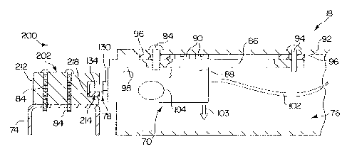
A first alternative embodiment load cell apparatus 200 is shown in
Figs. 9 and 10. Many of the components of load cell apparatus 200 are
substantially
the same as components of load cell apparatus 100 and therefore, like
reference
numerals are used to denote like components. Load cell apparatus 200 includes
a
mount 202 having a bore 204 formed therein. Bore 204 has a substantially
square-
shaped cross section and extends from an opening206 formed at a front surface
208 of
mount 202 to an end surface 210 that is positioned to lie between front
surface 208
and a rear surface 212 of mount 202.
Load cell apparatus 200 includes a liner 214 as shown in Figs. 9 and
10. Liner 214 comprises a quantity of material configured as a flat pad that
is
received in the bore 202. Liner 214 may be made of any of the materials
described
above in connection with liner 142 so long as liner 214 is more lubrous than
the
material from which mount 202 and/or stud 78 is made. Liner 214 is either
press fit
between inner side walls 216 of mount 202 or is adhered to a bottom inner
surface
218 of mount 202 or both. In addition, cylindrical portion 134 of stud 78
rests upon
liner 214.
A second alternative embodiment load cell apparatus 300 is shown in
Figs. 11 and 12. Many of the components of load cell apparatus 300 are
substantially
the same as components of load cell apparatus 100 and therefore, like
reference
numerals are used to denote like components. Load cell apparatus 300 includes
a
mount 302 having a bore 304 formed therein. Bore 304 has a substantially
square-
CA 02385825 2002-03-26
WO 01/23847 PCT/US00/26406
-10-
shaped cross section and extends from an opening306 formed at a front surface
308 of
mount 302 to an end surface 310 that is positioned to lie between front
surface 308
and a rear surface 312 of mount 302. Load cell apparatus 300 also includes a
stud 378
having a hex nut portion 380, a connector portion 382 extending from portion
380,
and a spherical portion 384 appended to portion 382 as shown in Fig. 11. In
addition,
stud 378 includes a threaded portion (not shown) that is substantially similar
to
threaded portion 132 of stud 78 of load cell apparatus 100.
Load cell apparatus 300 further includes a liner 314 as shown in Figs.
11 and 12. Liner 314 comprises a quantity of material configured as a flat pad
that is
received in bore 302. Liner 314 may be made of any of the materials described
above
in connection with liner 142 so long as liner 314 is more lubrous than the
material
from which mount 302 and/or stud 378 is made. Liner 314 is either press fit
between
inner side walls 316 of mount 302 or is adhered to a bottom inner surface 318
of
mount 302 or both. In addition, spherical portion 384 of stud 378 rests upon
liner
314.
A fourth alternative embodiment load cell apparatus 400 is shown in
Figs. 13 and 14. Many of the components of load cell apparatus 400 are
substantially
the same as components of load cell apparatus 100 and therefore, like
reference
numerals are used to denote like components. Load cell apparatus 400 includes
a
mount 402 having a bore 404 formed therein. Bore 404 is bounded by a
cylindrical
bore surface 422 that extends from an opening 406 formed at a front surface
408 of
mount 402 to an end surface 410 that is positioned to lie between front
surface 408
and a rear surface 412 of mount 402.
Load cell apparatus 400 includes a liner 414 as shown in Figs. 9 and
10. Liner 414 comprises a quantity of material that coats cylindrical portion
134 of
stud 78. Liner 414 may be made of any of the materials described above in
connection with liner 142 so long as liner 414 is more lubrous than the
material from
which mount 402 and/or stud 78 is made. Liner 414 is either press fit onto
cylindrical
portion 134 of stud 78 or is adhered thereto or both. Optionally, liner 414
may be
fashioned as a cap, as shown in Fig. 13, or a cylindrical sleeve (not shown)
that has an
open end adjacent end surface 170 of cylindrical portion 134 of stud 78. In
either
case, the cylindrical outer surface 420 of liner 414 engages cylindrical bore
surface
CA 02385825 2002-03-26
WO 01/23847 PCT/US00/26406
-11-
422 of mount 402. The diameter of bore surface 222 is slightly larger than the
diameter of outer surface 420 of liner 414 to provide a small amount of
diametral
clearance therebetween. In addition, bore 404 of mount 402 is sized such that
axial
clearance exits between an end surface 424 of liner and end surface 410.
A fifth alternative embodiment load cell apparatus 500 is shown in
Figs. 15 and 16. Many of the components of load cell apparatus 500 are
substantially
the same as components of load cell apparatus 100 and therefore, like
reference
numerals are used to denote like components. Load cell apparatus 500 includes
a
mount 502 having a bore 504 formed therein. Bore 504 has a substantially
square-
shaped cross section and extends from an opening 506 formed at a front surface
508
of mount 502 to an end surface 510 that is positioned to lie between front
surface 508
and a rear surface 512 of mount 502. Load cell apparatus 500 also includes a
stud 578
having a hex nut portion 580, a connector portion 582 extending from portion
580,
and a spherical portion 584 appended to portion 582 as shown in Fig. 15. In
addition,
stud 578 also includes a threaded portion (not shown) that is substantially
similar to
threaded portion 132 of stud 78 of load cell apparatus 100.
Load cell apparatus 500 includes a liner 514 as shown in Figs. 15 and
16. Liner 514 comprises a quantity of material fashioned as an O-ring that is
coupled
to spherical portion 584. Alternatively, spherical portion 584 is coated with
a quantity
of material to provide the liner. Liner 514 may be made of any of the
materials
described above in connection with liner 142 so long as liner 514 is more
lubrous than
the material from which mount 502 and/or stud 578 is made. Liner 514 is
received in
a groove formed around spherical portion 584. Optionally adhesive may be used
between O-ring 514 and portion 584. O-ring 514 engages a bottom inner surface
522
of mount 502.
Those skilled in the art will appreciate that the bores formed in the
mounts of the respective above-described embodiments may have shapes other
than
those illustrated without exceeding the scope of the present invention. For
example,
bores that are shown as having square-shaped cross sections may instead have
cylindrical cross sections and vice versa. In addition, the bores formed in
the mounts
of each of the respective embodiments may be hexagonal, octagonal, etc. and
the
liners used with such mounts would be shaped accordingly. In addition, those
skilled
CA 02385825 2002-03-26
WO 01/23847 PCT/US00/26406
-12-
in the art will appreciate that, although the bores formed in the mounts of
the
respective above-described embodiments terminate within the respective mounts,
it is
within the scope of the invention as presently perceived for the bores to
extend all the
way through the mounts such that the respective mounts are generally tubular.
Those skilled in the art will appreciate that, although the load cell
apparatus are described herein as being coupled to a base frame 12 and a weigh
frame
18, it is within the scope of the present invention for the load cell
apparatus to couple
to any type of structure or support. Therefore, the term "structure" as used
in the
claims is intended to be non-limiting and to mean any and all types of frames,
bases,
structures, supports, pedestals, decks, etc. In addition, although the each of
the load
cell apparatus described herein include cell block 70, those skilled in the
art will
appreciate that other types of cell blocks, load beams, and load members may
be used
in lieu of cell block 70. Therefore, the term "cell block" as used in the
claims is
intended to mean load members of all types and of all shapes.
Although the invention has been described in detail with reference to
certain illustrated embodiments, variations and modifications exist within the
scope
and spirit of the invention as described and as defined in the following
claims.