Language selection

Search

Patent 2385979 Summary

Third-party information liability

Some of the information on this Web page has been provided by external sources. The Government of Canada is not responsible for the accuracy, reliability or currency of the information supplied by external sources. Users wishing to rely upon this information should consult directly with the source of the information. Content provided by external sources is not subject to official languages, privacy and accessibility requirements.

Claims and Abstract availability

Any discrepancies in the text and image of the Claims and Abstract are due to differing posting times. Text of the Claims and Abstract are posted:

  • At the time the application is open to public inspection;
  • At the time of issue of the patent (grant).
(12) Patent Application: (11) CA 2385979
(54) English Title: AIR FLOW STRUCTURE FOR AN UPRIGHT-TYPE VACUUM CLEANER
(54) French Title: STRUCTURE DE CIRCULATION D'AIR POUR ASPIRATEUR VERTICAL
Status: Deemed Abandoned and Beyond the Period of Reinstatement - Pending Response to Notice of Disregarded Communication
Bibliographic Data
(51) International Patent Classification (IPC):
  • A47L 09/00 (2006.01)
  • A47L 09/22 (2006.01)
(72) Inventors :
  • PARK, JUNG-SEON (Republic of Korea)
  • YANG, IL-WON (Republic of Korea)
  • JEON, HYUNG-IL (Republic of Korea)
(73) Owners :
  • SAMSUNG KWANGJU ELECTRONICS CO., LTD.
(71) Applicants :
  • SAMSUNG KWANGJU ELECTRONICS CO., LTD. (Republic of Korea)
(74) Agent: SMART & BIGGAR LP
(74) Associate agent:
(45) Issued:
(22) Filed Date: 2002-05-10
(41) Open to Public Inspection: 2003-07-31
Examination requested: 2003-12-09
Availability of licence: N/A
Dedicated to the Public: N/A
(25) Language of filing: English

Patent Cooperation Treaty (PCT): No

(30) Application Priority Data:
Application No. Country/Territory Date
2002-0005619 (Republic of Korea) 2002-01-31

Abstracts

English Abstract


An air flow structure for an upright-type vacuum cleaner having a body
divided by a partition into a dust-collecting chamber having a dust bag and a
motor
driving chamber having a motor; an air suction port protruded at an upper part
of the
dust-collecting chamber in order to draw air thereinto, and having the dust
bag
disposed around the air suction port; a dust cover to cover the dust-
collecting
chamber and having a plurality of ribs disposed therein in a lengthwise
direction, a
concaved portion formed at a rear wall of the dust-collecting chamber in a
lengthwise direction, and a grill portion formed between the dust-collecting
chamber
and the motor driving chamber in order to allow the air of the dust-collecting
chamber to flow to the motor driving chamber.


Claims

Note: Claims are shown in the official language in which they were submitted.

WHAT IS CLAIMED IS:
1. An air flow structure for an upright-type vacuum cleaner comprising:
a body divided by a partition into a dust-collecting chamber having a dust
bag and a motor driving chamber having a motor;
an air suction port protruding from an upper part of the dust-collecting
chamber in order to draw air into the dust bag being disposed around the air
suction
port;
A dust cover to cover the dust-collecting chamber which has a plurality of
ribs disposed therein in a lengthwise direction in order to form an air
passage;
a second air passage formed as a concave portion at a rear wall of the
dust-collecting chamber in a lengthwise direction; and
a grill portion formed at the partition of the body in order to allow air to
flow
from the dust-collecting chamber to the motor driving chamber.
2. The air flow structure of claim 1, wherein the concave portion is
formed at the rear wail of the dust-collecting chamber and extending from the
air
suction port to the partition.
3. The air flow structure of claim 1, wherein the concave portion is formed
in a symmetrical manner with respect to a center line of the air suction port.
7

Description

Note: Descriptions are shown in the official language in which they were submitted.


CA 02385979 2002-05-10
AIR FLOW STRUCTURE FOR AN UPRIGHT-TYPE VACUUM CLEANER
BACKGROUND OF THE INVENTION
1. Fieid of the Invention
The present invention relates generally to an upright-type vacuum cleaner,
and more particularly, to an air flow structure for an upright-type vacuum
cleaner.
2. Description of the Prior Art
A conventional upright-type vacuum cleaner performs cleaning of a cleaning
surface such as a floor or a carpet by drawing dust and dirt entrained in air
from the
outside by using a suction force generated inside of a cleaner body.
As shown in FIG. 1, the conventional upright-type vacuum cleaner has a
suction brush 2 disposed at a lower part of the cleaner body 1. The upper
inside of
the cleaner body 1 has a dust-coNecting chamber to embrace a dust bag and the
lower inside of the cleaner body 1 has a motor driving chamber 30 having a
motor.
The dust-collecting chamber includes a dust cover 10. A handle 3 to move the
suction brush 1 is disposed on an upper part of the cleaner body 1.
When the motor is driven in the above structure, a strong suction force is
generated by the suction brush 2. The air containing dust and filth from the
surface
to be cleaned facing the suction brush 2 is drawn into the cleaner body 1 by
the
suction force. The drawn air is discharged through the dust bag in the dust-
collecting chamber and into the motor driving chamber 30 through a grill
portion
1

CA 02385979 2002-05-10
disposed between the dust-collecting chamber and the motor driving chamber 30.
The dust and dirt in the air is collected in the dust bag and filtered air is
discharged
to the outside through a discharging grill 40 after passing through the motor
driving
chamber 30.
When the dust and dirt are collected in the dust bag, the dust bag expands. If
the dust bag expands enough to come into close contact with the inside of the
dust-
collecting chamber, the flow of the air is. hindered, the suction force is
weakened,
and the motor is overloaded. Therefore, the vacuum cleaner has an air flow
structure in the dust-collecting chamber.
FIG. 2 is an exploded perspective view showing an upright-type vacuum
cleaner having a conventional air flow structure. As shown in FIG. 2, the
conventional air flow structure has a plurality of ribs 11 disposed at the
dust cover 10
in a lengthwise direction. Accordingly, the expanded dust bag is supported by
the
ribs 11, and thus some space for the air to flow is defined by the ribs 11
between the
dust cover 10 and the dust bag.
However, in the above air flow structure, the ribs 11 are disposed in the dust
cover 10 to form the air passage in front of the dust bag. However, the dust
bag in the
dust-collecting chamber 20 expands in both directions, front and back.
Therefore, the
air cannot flow easily at the back of the dust bag when fully expanded.
Accordingly,
there is a problem of weakening of the suction force of the vacuum cleaner
when the
dust bag expands, which causes the motor to be overloaded.
2

CA 02385979 2002-05-10
SUMMARY OF THE INVENTION
An object of the present invention is to provide an air flow structure for an
upright-type vacuum cleaner to prevent weakening of the suction force and
overloading of the motor due to the expansion of dust bag against the dust
collecting
chamber.
The above object is accomplished by providing an air flow structure for an
upright-type vacuum cleaner comprising: a body divided by a partition into a
dust-
collecting chamber having a dust bag and a motor driving chamber having a
motor;
an air suction port protruding from an upper part of the dust-collecting
chamber in
order to draw in air, and having the dust bag disposed around the air suction
port; a
dust cover closing the dust-collecting chamber and having a plurality of ribs
disposed therein in a lengthwise direction in order to form an air passage; a
second
air passage formed as a concave portion at the rear wall of the dust-
collecting
chamber, in a lengthwise direction; and a grill portion formed at the
partition of the
body in order to allow the air of the dust-collecting chamber to flow into the
motor
driving chamber.
Accordingly, a space for the air to flow both in back of and in front of the
dust
bag in the dust-collecting chamber is provided. Thus, weakening of the suction
force
and overloading of the motor due to the expansion of dust bag can be prevented
or
minimized.
BRIEF DESCRIPTION OF THE DRAWINGS
The object and features of the present invention will be more apparent by a
3
____... .___...T.....___.-..~,....".._. .._.._..~...-_-... _~.__.....,
.._,......~... _...._......__, ,. _~... .. _..

CA 02385979 2002-05-10
description of the preferred embodiment of the present invention by referring
to the
appended drawings, in which:
FIG. 1 is a perspective view schematically showing the structure of a
conventional upright-type vacuum cleaner;
FIG. 2 is an exploded perspective view showing an upright-type vacuum
cleaner applying a conventional air flow structure; and
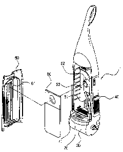
FIG. 3 is an exploded perspective view showing an upright-type vacuum
cleaner applying an air flow structure according to the present invention.
1:0 DETAILED DESCRIPTION OF THE PREFERRED EMBODIMENT
The preferred embodiment of the present invention will be described in
greater detail by referring to the appended drawing FIG. 3.
As shown in FIG. 3, an air flow structure for an upright-type vacuum cleaner
according to the present invention includes a body 1 divided into a dust-
collecting
chamber 50 and a motor driving chamber 30, a grill portion 71 to draw air
through
the dust-collecting chamber 50 and into the motor driving chamber 30, and a
concave portion 51 formed at the rear wail of the dust-collecting chamber 50
as a
second air passage.
The inside of the body 1 is divided by a partition 70 into the dust-collecting
chamber 50 having a dust bag 80 and the motor driving chamber 30 having a
motor
(not shown). An air suction part 52 in communication with the outside is
formed at
an upper part of the dust-collecting chamber 50 to draw the outside air
therethrough.
The dust-collecting chamber 50 and the motor driving chamber 30 are in
4

CA 02385979 2002-05-10
communication with each other through the grill portion 71 disposed in the
partition
70. When the motor is driven and the suction force is generated in the motor
driving
chamber 30, the air of the dust-rx~llecting chamber 50 is drawn into the motor
driving
chamber 30 through the grill portion 71. In addition, a discharging grill 40,
to
discharge the air from the motor driving chamber 30 to the outside, is
disposed at a
side of the cleaner body 1.
A dust cover 60 closes the dust-collecting chamber 50, and a plurality of ribs
61
are disposed at the inner wall of the dust cover 60. The ribs 61 are disposed
in a
lengthwise direction on the dust cover 60 so as to form one or more air
passages.
The concave portion 51 is formed at the rear wall of the dust-collecting
chamber
50 in a lengthwise direction. Accordingly, the second air passage for the air
to flow
is defined between the dust bag 80 in the air suction port 52 of the dust-
collecting
chamber 50 and the rear wall of the dust-collecting chamber 50. The concave
portion 51 is formed at the rear wall of the dust-collecting chamber 50 to
allow the air
IS passed through the dust bag 80 to easily flow to the motor driving chamber
30
through the grill portion 71. In addition, the concave portion 51 is formed in
a
symmetrical manner with respect to the center line of the air suction port 52.
The operation of the upright-type vacuum cleaner applying the air flow
structure
according to the present invention will be described below.
2O When the motor in the cleaner body 1 is driven, a strong suction force is
generated in the motor driving chamber 30. The dust and dirt on the surface to
be
cleaned is drawn into the dust bag 80 in the dust-collecting chamber 50 with
the
drawn air through a hose (not shown) and an air suction port 52, by the
suction force.
5

CA 02385979 2002-05-10
The drawn air flows into the dust-collecting chamber 50 after the dust and
dirt is
f
separated out by passing through the dust bag 80. The filtered air in the dust-
collecting chamber 50 is drawn into the motor driving chamber 30 through the
grill
portion 71 and discharged to the outside of the cleaner body 1 through the
discharging grill 40.
When the dust bag 80 expands, the dust bag 80 is supported by contact with
the rear wall of the dust-collecting chamber 50 and the plurality of ribs 61
disposed
at the dust cover 60. A space for the air to flow is formed between the inner
wall of
the dust cover 60 and the dust bag 80. Moreover, a space is defined between
the
rear wall of the dust-collecting chamber 50 and the dust bag 80 by the concave
portion 51. Therefore, a passage for the filtered air passed through the dust
bag 80
to flow to the motor driving chamber 30 through the grill portion 71 is
defined in both
the front and rear sides of the dust-collecting chamber 50.
According to the present invention constructed as above described, a passage
for the air to flow is formed by the concave portion 51 formed on the rear
watt of the
dust-collecting chamber 50. Thus, an air passage is formed not only in the
front of
the dust bag 80 but also in the back of the dust bag 80. Accordingly, the
suction
force remains strong even when the dust bag 80 expands, and the motor is not
overloaded.
The preferred embodiment of the present invention has been illustrated and
described. However, the present invention is not limited to the preferred
embodiment
described here, and someone skilled in the art can modify the present
invention
without distorting the point of the present invention as claimed in the
following claims.
6

Representative Drawing
A single figure which represents the drawing illustrating the invention.
Administrative Status

2024-08-01:As part of the Next Generation Patents (NGP) transition, the Canadian Patents Database (CPD) now contains a more detailed Event History, which replicates the Event Log of our new back-office solution.

Please note that "Inactive:" events refers to events no longer in use in our new back-office solution.

For a clearer understanding of the status of the application/patent presented on this page, the site Disclaimer , as well as the definitions for Patent , Event History , Maintenance Fee  and Payment History  should be consulted.

Event History

Description Date
Application Not Reinstated by Deadline 2007-08-17
Inactive: Dead - Final fee not paid 2007-08-17
Deemed Abandoned - Failure to Respond to Maintenance Fee Notice 2007-05-10
Deemed Abandoned - Conditions for Grant Determined Not Compliant 2006-08-17
Inactive: IPC from MCD 2006-03-12
Notice of Allowance is Issued 2006-02-17
Letter Sent 2006-02-17
Notice of Allowance is Issued 2006-02-17
Inactive: Approved for allowance (AFA) 2006-01-10
Letter Sent 2003-12-22
Request for Examination Requirements Determined Compliant 2003-12-09
All Requirements for Examination Determined Compliant 2003-12-09
Request for Examination Received 2003-12-09
Application Published (Open to Public Inspection) 2003-07-31
Inactive: Cover page published 2003-07-30
Inactive: First IPC assigned 2002-08-08
Inactive: Filing certificate - No RFE (English) 2002-06-20
Letter Sent 2002-06-20
Application Received - Regular National 2002-06-20

Abandonment History

Abandonment Date Reason Reinstatement Date
2007-05-10
2006-08-17

Maintenance Fee

The last payment was received on 2006-04-13

Note : If the full payment has not been received on or before the date indicated, a further fee may be required which may be one of the following

  • the reinstatement fee;
  • the late payment fee; or
  • additional fee to reverse deemed expiry.

Patent fees are adjusted on the 1st of January every year. The amounts above are the current amounts if received by December 31 of the current year.
Please refer to the CIPO Patent Fees web page to see all current fee amounts.

Fee History

Fee Type Anniversary Year Due Date Paid Date
Registration of a document 2002-05-10
Application fee - standard 2002-05-10
Request for examination - standard 2003-12-09
MF (application, 2nd anniv.) - standard 02 2004-05-10 2004-04-19
MF (application, 3rd anniv.) - standard 03 2005-05-10 2005-04-26
MF (application, 4th anniv.) - standard 04 2006-05-10 2006-04-13
Owners on Record

Note: Records showing the ownership history in alphabetical order.

Current Owners on Record
SAMSUNG KWANGJU ELECTRONICS CO., LTD.
Past Owners on Record
HYUNG-IL JEON
IL-WON YANG
JUNG-SEON PARK
Past Owners that do not appear in the "Owners on Record" listing will appear in other documentation within the application.
Documents

To view selected files, please enter reCAPTCHA code :


To view images, click a link in the Document Description column (Temporarily unavailable). To download the documents, select one or more checkboxes in the first column and then click the "Download Selected in PDF format (Zip Archive)" or the "Download Selected as Single PDF" button.

List of published and non-published patent-specific documents on the CPD .

If you have any difficulty accessing content, you can call the Client Service Centre at 1-866-997-1936 or send them an e-mail at CIPO Client Service Centre.

({010=All Documents, 020=As Filed, 030=As Open to Public Inspection, 040=At Issuance, 050=Examination, 060=Incoming Correspondence, 070=Miscellaneous, 080=Outgoing Correspondence, 090=Payment})


Document
Description 
Date
(yyyy-mm-dd) 
Number of pages   Size of Image (KB) 
Representative drawing 2002-10-23 1 11
Description 2002-05-09 6 243
Abstract 2002-05-09 1 22
Claims 2002-05-09 1 29
Drawings 2002-05-09 3 61
Courtesy - Certificate of registration (related document(s)) 2002-06-19 1 134
Filing Certificate (English) 2002-06-19 1 173
Acknowledgement of Request for Examination 2003-12-21 1 188
Reminder of maintenance fee due 2004-01-12 1 107
Commissioner's Notice - Application Found Allowable 2006-02-16 1 162
Courtesy - Abandonment Letter (NOA) 2006-10-25 1 167
Courtesy - Abandonment Letter (Maintenance Fee) 2007-07-04 1 176