Language selection

Search

Patent 2385998 Summary

Third-party information liability

Some of the information on this Web page has been provided by external sources. The Government of Canada is not responsible for the accuracy, reliability or currency of the information supplied by external sources. Users wishing to rely upon this information should consult directly with the source of the information. Content provided by external sources is not subject to official languages, privacy and accessibility requirements.

Claims and Abstract availability

Any discrepancies in the text and image of the Claims and Abstract are due to differing posting times. Text of the Claims and Abstract are posted:

  • At the time the application is open to public inspection;
  • At the time of issue of the patent (grant).
(12) Patent Application: (11) CA 2385998
(54) English Title: ROTARY TOY
(54) French Title: JOUET ROTATIF
Status: Deemed Abandoned and Beyond the Period of Reinstatement - Pending Response to Notice of Disregarded Communication
Bibliographic Data
(51) International Patent Classification (IPC):
  • A63B 69/00 (2006.01)
  • A63B 21/005 (2006.01)
  • A63B 22/00 (2006.01)
  • A63B 43/00 (2006.01)
  • A63B 67/00 (2006.01)
  • A63B 67/14 (2006.01)
  • A63B 67/16 (2019.01)
  • A63B 69/36 (2006.01)
  • A63H 33/00 (2006.01)
(72) Inventors :
  • HURD, JEFFREY GRAHAM (Canada)
(73) Owners :
  • JEFFREY GRAHAM HURD
(71) Applicants :
  • JEFFREY GRAHAM HURD (Canada)
(74) Agent:
(74) Associate agent:
(45) Issued:
(22) Filed Date: 2002-05-13
(41) Open to Public Inspection: 2003-11-13
Availability of licence: N/A
Dedicated to the Public: N/A
(25) Language of filing: English

Patent Cooperation Treaty (PCT): No

(30) Application Priority Data: None

Abstracts

Sorry, the abstracts for patent document number 2385998 were not found.

Claims

Note: Claims are shown in the official language in which they were submitted.

I claim:
1. A rotary toy including: a base; a swivel mounted to said base; an elongated
element
connected at one end to said swivel; and a target connected to the other end
of said elongated
element and adapted to be struck.
2. The rotary toy of claim 1 wherein said target is a puck.
3. The rotary toy of claim 1 wherein said elongated element is a cord.
4. The rotary toy of claim 1 wherein said elongated element is a rod.
5. The rotary toy of claim 1 wherein said swivel includes an L-shaped bar
having an upstanding
vertical limb mounted in bearings in said base and a outwardly extending
horizontal limb to
which said elongated element is connected.
6. The rotary toy of claim 5 wherein said horizontal limb has an outer wall
having a circular
cross-section and being threaded adjacent to an outer end thereof; said rotary
toy including: a
sleeve; and a lug, said sleeve having a threaded inner wall of circular cross-
section for threadable
mating with said threaded outer wall, said sleeve extending beyond the end of
said horizontal
limb and terminating at an end which extends radially inward and terminates at
an opening of
smaller cross-section than that of said inner wall such that there is a space
within said sleeve
between said outer end and said opening, said lug being connected to the end
of said elongated
element opposite said target and having a cross section larger than that of
said opening, said lug
being received in said space and serving to connect said elongated element to
said swivel.

Description

Note: Descriptions are shown in the official language in which they were submitted.


CA 02385998 2002-05-13
BACKGRC>UND OF THE INVENTION
This invention relates to toys and more particularly to a rotary toy which has
a ball or
puck that is intended to be hit by an implement for striking such as a hockey
stick, bat or club.
The toy of my invention has a swivel to which an elongated inflexible rod or
flexible
cord is attached. A puck or ball is attached to the end of the rod or cord..
When the puck or ball is
sl:ruck, it will rotate about the swivel but will not separate from the toy.
The player need not
chase after the puck or ball after he has struck it, it will always be close
to where he is standing.
The toy is not only fun but is useful in improving the hand-eye coordination
of the player.
It: does so by indicating whether a ball or puck has been struck squarely. The
toy can also assist in
improving a player's timing by the addition of an electric motor to cause the
puck or ball to
rotate. The toy will then not only test the player's aim but also his timing.
If the ball or puck is attached by a flexible cord to the swivel, the player
can practice the
direction of his aim in order to raise or lower the ball or puck as it travels
through the air to a
desired height.
SUMMARY OF THE INVENTION
Briefly my rotary toy includes a base; a swivel mounted to the base; an
elongated element
connected at one end to the swivel; and. a target connected to the other end
of the elongated
element and adapted to be struck.
DESCRIPTION OF THE DRAWING
The rotary toy of the invention is described with reference to the
accompanying drawing

CA 02385998 2002-05-13
in which:
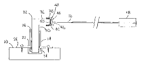
Figure 1 is an elevation of the to:y; and
Figure 2 is a plan view of the toy.
Like reference characters refer to like parts throughout the description of
the drawing.
DESCRIPTION OF PREFERRED EMBODIMENTS
With reference to the drawing, the rotary toy comprises a base 10, a swivel
14, an
elongated element 16 and a target 18. The base has an opening 20 adjacent to
each corner for
receipt of a spike (not illustrated) to anchor the base to the ground or a
screw for attachment to a
sheet of plywood lying on the ground or on a floor. The swivel has a circular
collar 22 which
includes a skirt 24 which is fastened to the base by means of screws or nails.
The upper portion
2fi of the collar is tubular and is open at the top for receipt of an upwardly
extending or vertical
limb 30 of an L-shaped bar 32. The bar has a circular cross-section throughout
its entire length.
Tlhe vertical limb is mounted in bearings 34 within a recess in the base and
is free to rotate or
swivel.
A horizontal limb 36 extends outwardly from the upper end of the vertical
limb. The
outer wall of the horizontal limb adjacent to its outer end is threaded at 38
and mates threadably
with the threaded inner wall of a sleeve 40. The inner wall has a circular
cross-section as does the
threaded outer wall of the limb.
The sleeve extends beyond the outer end of the limb and terminates at an end
44 which
ea;tends radially inward and terminates at an opening 46. The opening has a
smaller cross-section
2

CA 02385998 2002-05-13
than that of the inner wall of the sleeve. There is a space 48 within the
sleeve between the outer
end of the limb and the opening.
A lug 50 is accommodated in the space in the sleeve. The lug has a cross-
section larger
than that of the opening so that it is confined in the space when the sleeve
is attached to the
horizontal limb. The lug is connected to the end of the elongated element
opposite the target and
serves to connect the swivel to the elongated element and target.
The lug can be removed from i:he sleeve simply be unscrewing the sleeve and
removing it
from the limb. The target is then be removed from the end of the elongated
element and the
elongated element is drawn through the opening in the sleeve and out of it.
Elongated element 16 may be flexible or inflexible. If it is flexible it may
be twine, wire
or a cord composed of flexible polymeric material such as polypropylene. If
the elongated
element is inflexible, it may be a rod which is composed of inflexible
polymeric material or of a
metal such as steel. The target is preferably a puck but it may be a ball,
balloon or whatever else
is desired.
Preferably the elongated element is about 3 feet in length where the toy is
used purely for
amusement. If the toy is used for anofher purpose such as for practising
batting or golfing swings,
the elongated element can be longer. if the element is inflexible, the length
of the vertical limb of
the L-shaped bar can be made adjustable by conventional means so that its
length will be
appropriate to what is attached to it a;. a target. For example, if the target
is a baseball then the
vertical limb should be long enough to support the ball at waist to shoulder
height. If the target is
3

CA 02385998 2002-05-13
a puck the limb should support the puck so that it is near or on the ground.
If desired, the bar may be rotated by a conventional motor mounted within the
base. The
speed of the motor can be variable in order to adjust the speed at which the
target is rotating. A
conventional clutch can be provided so that the motor will not be damaged when
the target is
struck with resulting sudden increase or decrease of its speed. A counter for
computing the
number of rotations of the bar and a timer for measuring intervals of time can
also be provided.
An monitor can be provided for displaying the speed of rotation of the bar,
the number of
times it has rotated in a given time interval and other predetermined time
intervals. Such a
display would be useful where the toy is used in competitions where
participants are each
allowed a given period of time to strike the target. The speed of rotation
could be set according to
the abilities of the participants and a point would be awarded to a
participant each time he struck
the target.
It will be understood of course that modifications can be made in the rotary
toy illustrated
and described in this application without departing from the scope and purview
of the invention
as defined in the claims that follow.
4

Representative Drawing
A single figure which represents the drawing illustrating the invention.
Administrative Status

2024-08-01:As part of the Next Generation Patents (NGP) transition, the Canadian Patents Database (CPD) now contains a more detailed Event History, which replicates the Event Log of our new back-office solution.

Please note that "Inactive:" events refers to events no longer in use in our new back-office solution.

For a clearer understanding of the status of the application/patent presented on this page, the site Disclaimer , as well as the definitions for Patent , Event History , Maintenance Fee  and Payment History  should be consulted.

Event History

Description Date
Revocation of Agent Requirements Determined Compliant 2020-09-01
Inactive: IPC from MCD 2006-03-12
Inactive: Dead - Application incomplete 2005-01-24
Application Not Reinstated by Deadline 2005-01-24
Deemed Abandoned - Failure to Respond to Maintenance Fee Notice 2004-05-13
Deemed Abandoned - Failure to Respond to Notice Requiring a Translation 2004-01-26
Application Published (Open to Public Inspection) 2003-11-13
Inactive: Cover page published 2003-11-12
Inactive: Incomplete 2003-10-24
Inactive: IPC assigned 2002-08-16
Inactive: First IPC assigned 2002-08-16
Application Received - Regular National 2002-06-20
Filing Requirements Determined Compliant 2002-06-20
Inactive: Filing certificate - No RFE (English) 2002-06-20

Abandonment History

Abandonment Date Reason Reinstatement Date
2004-05-13
2004-01-26

Fee History

Fee Type Anniversary Year Due Date Paid Date
Application fee - small 2002-05-13
Owners on Record

Note: Records showing the ownership history in alphabetical order.

Current Owners on Record
JEFFREY GRAHAM HURD
Past Owners on Record
None
Past Owners that do not appear in the "Owners on Record" listing will appear in other documentation within the application.
Documents

To view selected files, please enter reCAPTCHA code :


To view images, click a link in the Document Description column. To download the documents, select one or more checkboxes in the first column and then click the "Download Selected in PDF format (Zip Archive)" or the "Download Selected as Single PDF" button.

List of published and non-published patent-specific documents on the CPD .

If you have any difficulty accessing content, you can call the Client Service Centre at 1-866-997-1936 or send them an e-mail at CIPO Client Service Centre.


Document
Description 
Date
(yyyy-mm-dd) 
Number of pages   Size of Image (KB) 
Abstract 2003-11-12 1 2
Representative drawing 2002-11-17 1 6
Description 2002-05-12 4 152
Drawings 2002-05-12 1 14
Claims 2002-05-12 1 39
Filing Certificate (English) 2002-06-19 1 172
Reminder of maintenance fee due 2004-01-13 1 107
Courtesy - Abandonment Letter (incomplete) 2004-02-15 1 168
Courtesy - Abandonment Letter (Maintenance Fee) 2004-07-07 1 175
Correspondence 2002-06-19 1 11
Correspondence 2003-10-23 1 17