Language selection

Search

Patent 2386178 Summary

Third-party information liability

Some of the information on this Web page has been provided by external sources. The Government of Canada is not responsible for the accuracy, reliability or currency of the information supplied by external sources. Users wishing to rely upon this information should consult directly with the source of the information. Content provided by external sources is not subject to official languages, privacy and accessibility requirements.

Claims and Abstract availability

Any discrepancies in the text and image of the Claims and Abstract are due to differing posting times. Text of the Claims and Abstract are posted:

  • At the time the application is open to public inspection;
  • At the time of issue of the patent (grant).
(12) Patent Application: (11) CA 2386178
(54) English Title: TWO SOLENOID PRESSURE MODULATED RELAY VALVE WITH INTEGRAL QUICK RELEASE FUNCTION FOR ABS
(54) French Title: VALVE RELAIS MODULEE PAR PRESSION DE DEUX SOLENOIDES DOTEE D'UNE FONCTION DE VIDANGE RAPIDE INTEGRALE
Status: Deemed Abandoned and Beyond the Period of Reinstatement - Pending Response to Notice of Disregarded Communication
Bibliographic Data
(51) International Patent Classification (IPC):
  • B60T 8/36 (2006.01)
  • B60T 8/50 (2006.01)
  • B60T 13/68 (2006.01)
  • B60T 15/02 (2006.01)
(72) Inventors :
  • ROSS, CHARLES E. (United States of America)
(73) Owners :
  • BENDIX COMMERCIAL VEHICLE SYSTEMS LLC
(71) Applicants :
  • BENDIX COMMERCIAL VEHICLE SYSTEMS LLC (United States of America)
(74) Agent: MACRAE & CO.
(74) Associate agent:
(45) Issued:
(86) PCT Filing Date: 2000-09-29
(87) Open to Public Inspection: 2001-04-12
Examination requested: 2005-07-11
Availability of licence: N/A
Dedicated to the Public: N/A
(25) Language of filing: English

Patent Cooperation Treaty (PCT): Yes
(86) PCT Filing Number: PCT/US2000/026923
(87) International Publication Number: WO 2001025067
(85) National Entry: 2002-03-28

(30) Application Priority Data:
Application No. Country/Territory Date
09/410,519 (United States of America) 1999-10-01

Abstracts

English Abstract


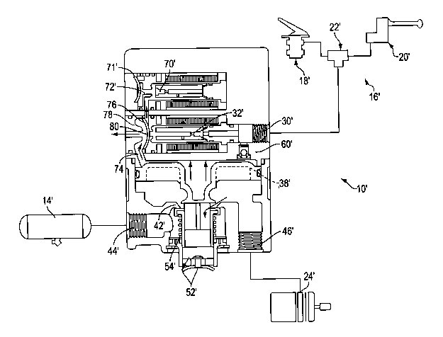
The improved ABS performance in an air brake system for a vehicle is achieved
by rapidly exhausting air from a control volume (36) of the relay valve piston
(38'). The preferred embodiment incorporates a quick release valve (78) in the
control air circuit to allow a majority of the air in the control cavity to
escape directly to ambient. The orifice (72') through the exhaust solenoid
(70') need only handle a relatively small volume of air upstream of the quick
release valve, i.e., between the quick release diaphragm (76) and the inlet
solenoid seat (80). Improved performance can be obtained through simple
modification of the prior art structure.


French Abstract

On obtient une performance améliorée dans un système de frein à air comprimé destiné à un véhicule en laissant s'échapper rapidement l'air d'un volume de commande (36) du piston de la valve relais (38'). Le mode de réalisation préféré concerne une valve de vidange rapide (78) dans le circuit d'air de commande permettant à la majorité d'air dans la cavité de commande de s'échapper directement dans l'air ambiant. L'orifice (72') à travers le solénoïde d'échappement (70') ne doit manipuler qu'un volume relativement petit d'air en amont de la valve de vidange rapide, par exemple, entre le diaphragme de vidange rapide (76) et le support du solénoïde d'entrée (80). On peut obtenir une performance améliorée par simple modification de la structure de la technique antérieure.

Claims

Note: Claims are shown in the official language in which they were submitted.


-6-
Having thus described the invention, it is now claimed:
1. An ABS modulator relay valve assembly selectively controlling brake
application
to an associated brake chamber comprising:
a housing having a supply port, a delivery port, a control port, and an
exhaust
port;
a piston received in the housing defining a control volume and movable in
response to a pressure signal from the control port to control communication
among the supply,
delivery, and exhaust ports; and
hold and exhaust valve assemblies associated with antilock braking function in
communication with the control volume and including a quick release valve
interposed between
the hold valve and the control volume to provide a direct passage to
atmosphere.
2. The valve assembly of claim 1 wherein the quick release valve includes a
flexible
member selectively engaging a valve seat.
3. The valve assembly of claim 2 wherein the valve seat is disposed at one end
of
the hold exhaust assembly.
4. The valve assembly of claim 1 wherein the hold and exhaust valve assemblies
are
solenoid valves having coils associated therewith to selectively actuate the
hold and exhaust
valve assemblies in response to an electrical control signal indicative of an
ABS event.
5. The valve assembly of claim 1 wherein the quick release valve is integral
to the
hold valve assembly.
6. A method of quickly exhausting a control volume defined on one side of a
piston
in an antilock braking system having a hold valve and an exhaust valve
operatively associated
therewith, and control, supply, delivery, and exhaust ports selectively
regulating supply of air to
brake chambers associated with the wheels, the method comprising the steps of:

7
connecting the supply and delivery ports for service braking in response to a
signal at the control port;
connecting the delivery and exhaust ports to release service braking in
response
to the absence of a signal at the control port;~
controlling air pressure in the control volume via the hold and exhaust valves
in
response to an antilock control event; and
exhausting a major portion of air from the control volume during the antilock
control event through a quick release valve disposed upstream of the exhaust
valve to increase
performance response of the antilock braking system.

Description

Note: Descriptions are shown in the official language in which they were submitted.


CA 02386178 2002-03-28
WO 01/25067 PCT/US00/26923
TWO SOLENOID PRESSURE MODULATED RELAY VALVE WITH
INTEGRAL QUICK RELEASE FUNCTION FOR ABS
Background of the Invention
This application relates to the art of braking systems, and more particularly
to an
antilock brake system (ABS) modulator relay valve. The invention is
particularly applicable to
a tractor or tractor-trailer type vehicle equipped with an air braking system
in which a vehicle
operator generates a control signal to operate a brake control valve. The
signal is transmitted to
relay valves which communicate compressed air from storage reservoirs to
vehicle brakes. It will
be appreciated, however, that the invention may relate to similar environments
and applications.
A modulator relay valve for ABS brake systems typically includes an
impermeable or solid walled piston or flexible diaphragm that selectively
moves during normal
service braking to establish communication among supply, delivery, and exhaust
ports. The
piston is responsive to a control signal provided, for example, from a foot
brake valve or trailer
control valve. The piston then selectively activates an inlet/exhaust valve to
selectively connect
the supply, delivery, and exhaust ports. In response to an antilock control
event, a solenoid
control assembly provides for a rapid pulsing of the brake application. That
is, if an antilock
event is sensed, an electronic control unit sends suitable signals to solenoid
valve assemblies
associated with the modulator. The valve assemblies provide an electro-
pneumatic interface
between the electronic control unit and the airbrake system. If an impending
wheel lockup is
sensed, the antilock controller immediately begins to modify brake application
using the
modulator. Air on one side of the modulator piston is controlled by
selectively opening and
closing the supply and exhaust solenoid valve assemblies. Coils associated
with the respective
solenoid valve assemblies are quickly energized or deenergized in a
predetermined sequence by
the controller. When the solenoid coil is energized, a core or shuttle is
moved to either open or
close an associated air passage. This either opens or closes the exhaust
passage or reapplies air
pressure to the brake actuator. By opening or closing the solenoid valves, the
anti-lock controller
simulates brake "pumping" but at a rate substantially faster than the driver
of a vehicle could
actually pump the brakes to avoid skidding.
To achieve good ABS performance in air brake vehicles, a significant factor is
the
ability to rapidly exhaust service air from the brake chamber. In known two
solenoid relay valve
arrangements, control air from a relay valve control cavity is exhausted
through an orificed
exhaust solenoid passage. As will be appreciated, the orificed exhaust passage
is relatively small.

CA 02386178 2002-03-28
WO 01/25067 PCT/US00/26923
-2-
One proposed solution is to employ a larger solenoid, i.e., a solenoid having
a larger orifice or
exhaust passage, so that the passage would not serve as a bottleneck for the
exhaust function
during an antilock control event. However, a larger solenoid is less efficient
and requires
additional power to operate. It is for these reasons that present arrangements
use an exhaust
solenoid of a predetermined size and exhaust the control air from the relay
valve control cavity
through the exhaust solenoid passage. Thus, any improvement that addresses
these concerns
would be desirable, particularly if easily incorporated into an existing
modulator valve without
substantial modification.
Summary of the Invention
The present invention contemplates an improved modulator relay valve
employing a quick release valve in the control air circuit to allow control
air contained therein
to escape directly to atmosphere.
In accordance with a preferred embodiment of the invention, a quick release
valve
is interposed between the control cavity and the exhaust solenoid. In this
manner, a majority of
the control air contained in the cavity is permitted to escape directly to
atmosphere through the
quick release valve. The exhaust solenoid passage need only exhaust the
relatively small volume
of air disposed between the quick release diaphragm and the supply solenoid
seat.
According to another aspect of the invention, the conventional antilock
braking
system is easily modified to incorporate this improvement.
A principal advantage of the invention is the ability to improve ABS
performance
on air braked vehicles.
Another advantage of the invention resides in the ability to achieve improved
exhaust of control air from the relay valve control cavity without increasing
the size and power
constraints associated with the present solenoid valve assembly.
Still another advantage of the invention is the ability to easily modify the
existing
system to incorporate this feature.
Still other advantages and benefits of the invention will become apparent to
those
skilled in the art upon a reading and understanding of the following detailed
description.

CA 02386178 2002-03-28
WO 01/25067 PCT/US00/26923
-3-
Brief Description of the Drawings
The invention may take physical form in certain parts and arrangements of
parts,
a preferred embodiment of which will be described in detail in this
specification. The preferred
embodiment is illustrated in the accompanying drawings and forms a part of the
invention,
wherein:
FIGURE 1 is a schematic representation of a prior art, two solenoid modulating
relay valve assembly shown in a normal service application position;
FIGURE 2 is a view similar to FIGURE 1 illustrating the relay valve in a
balanced or hold position;
FIGURE 3 illustrates the prior arrangement in a service application release
position;
FIGURE 4 illustrates ABS operation where the exhaust port of the solenoid
assembly is opened to simulate pumping of the brakes;
FIGURE 5 is a schematic representation of the new invention; and
FIGURE 6 is a graphical representation of the improved exhaust feature
provided
by the present invention.
Detailed Description of the Preferred Embodiment
FIGURES 1-4 illustrate a conventional pressure modulating relay valve assembly
10 having a housing 12 that communicates with an air supply or pressurized air
reservoir 14 and
a control valve 16, which may include a foot-brake valve 18 and a trailer
control valve 20
interconnected, for example, by a double-check valve 22. The relay valve
housing 12 also
communicates with a service brake chamber 24. A control port 30 selectively
receives an air
pressure signal from either the brake valve or trailer control valve. The air
passes through an
inlet or supply solenoid valve assembly 32 and passage 34 for communication
with a control
volume or cavity 36 defined by a first or upper face of the piston 38
sealingly received in the
housing. The pressurized air acts on the piston and urges it toward a position
as shown in
FIGURE 1 where an inlet/exhaust valve 40 opens communication between the
storage reservoir
14 and the brake chamber 24. That is, a lower side of the relay piston 38
engages and urges the
inlet/exhaust valve from associated seat 42. This establishes communication
between the air

CA 02386178 2002-03-28
WO 01/25067 PCT/US00/26923
-4-
reservoir 14 and the brake chamber 24 as illustrated by the arrows in FIGURE
1. Thus, supply
port 44 communicates with delivery port 46. The movement of the piston also
engages a valve
seat 50 to preclude further communication with exhaust port 52. Consequently,
the brake
chamber 24 which is normally in communication with the exhaust port, is then
actuated or
pressurized by the air, as exhibited in FIGURE 1.
FIGURE 2 represents a balance or hold position where air is still communicated
from the brake trailer control valve to the port 30, thus pressurizing the
upper side of the piston.
Likewise, the second or underside of the piston has reached the state where
air pressure, in
conjunction with the biasing force of spring 54, provides for inlet/exhaust
valve 40 to be seated
against both valve seat 42 and valve seat 50.
In FIGURE 3, control pressure above the relay piston is exhausted as the valve
60 opens and air pressure is removed from the control port 30. The control
piston also unseats
from the valve seat 50 thus establishing communication between the brake
chamber 24 and
exhaust port 52. In this manner, the service brakes are released until the
next brake application
as demanded by the operator.
FIGURE 4 is representative of the antilock mode of the relay valve. Again,
when
an antilock controller senses impending wheel lock, electrical signals are
sent to the supply
solenoid 32 and exhaust solenoid 70. By selectively opening and closing the
solenoids, brake
pumping is simulated. More particularly, the supply solenoid is normally open
and when closed
prevents control line pressure from port 30 from further pressurizing control
cavity 36. On the
other hand, the exhaust solenoid 70 is normally closed. When opened, the
exhaust solenoid
provides a path for air pressure from the control volume 36, though passage
34, and through the
restricted orifice to reach ambient (as represented by the deflected shape of
exhaust diaphragm
71.
Because of the restricted orifice 72 through the exhaust solenoid assembly, a
need
exists for improved ABS performance and the ability to rapidly exhaust air
from the control
volume. FIGURE 5 illustrates the provision for a large exhaust passage 74 from
the control
cavity to an exhaust side of a diaphragm 76 of a quick release valve 78. As
will be appreciated,
the exhaust paths represented by passage 34 in the prior art embodiment of
FIGURES 1-4 are
preferably plugged to the exhaust solenoid. The additional passage 74 is cross-
drilled in the
housing to provide a large diameter passage 74 from the control volume to the
exhaust side of

CA 02386178 2002-03-28
WO 01/25067 PCT/US00/26923
-5-
the quick release valve 78. There is still a communication path between the
supply side of the
quick release diaphragm and the exhaust solenoid as represented by the arrow
in FIGURE 5. The
exhaust solenoid need only exhaust a relatively small volume of air upstream
of the quick release
valve, i.e., between the quick release diaphragm 76 and the hold or inlet
solenoid seat 80. The
majority of the control air in the control cavity 36 escapes directly to
ambient through passage
74 and the quick release valve 78. This effectively achieves the rapid exhaust
desired for
improved ABS performance.
FIGURE 6 is a graphic representation of the improvement achieved with the
present invention. Particularly, voltages are depicted by curve 90 in the
graph. The solenoid
current is represented by curve 92. The representative distinction between the
embodiment of
FIGURES 1-4 and that of FIGURE 5 is best exemplified by a comparison of the
air pressure
curves 94, 96. Although the air pressure decreases rapidly as illustrated by
curve 94, indicating
release of air pressure in the control cavity upon energization of the exhaust
solenoid, curve 96
has a steeper slope and more quickly exhausts the air pressure therefrom.
Incorporating the quick
release valve 78 and the large diameter passage 74 results in the increased
slope and improved
performance desired for ABS performance.
The invention has been described with reference to the preferred embodiment.
Obviously, modifications and alterations will occur to other upon reading and
understanding of
this specification. For example, alternative designs of a quick release valve
assembly can be used
to rapidly and efficiently exhaust air from the control volume. The present
invention is intended
to include such modifications and alterations in so far as they come within
the scope of the
appended claims or the equivalents thereof.

Representative Drawing
A single figure which represents the drawing illustrating the invention.
Administrative Status

2024-08-01:As part of the Next Generation Patents (NGP) transition, the Canadian Patents Database (CPD) now contains a more detailed Event History, which replicates the Event Log of our new back-office solution.

Please note that "Inactive:" events refers to events no longer in use in our new back-office solution.

For a clearer understanding of the status of the application/patent presented on this page, the site Disclaimer , as well as the definitions for Patent , Event History , Maintenance Fee  and Payment History  should be consulted.

Event History

Description Date
Application Not Reinstated by Deadline 2008-05-29
Inactive: Dead - No reply to s.30(2) Rules requisition 2008-05-29
Deemed Abandoned - Failure to Respond to Maintenance Fee Notice 2007-10-01
Inactive: Abandoned - No reply to s.30(2) Rules requisition 2007-05-29
Inactive: S.30(2) Rules - Examiner requisition 2006-11-29
Inactive: IPC from MCD 2006-03-12
Letter Sent 2005-08-11
Request for Examination Received 2005-07-11
Amendment Received - Voluntary Amendment 2005-07-11
All Requirements for Examination Determined Compliant 2005-07-11
Request for Examination Requirements Determined Compliant 2005-07-11
Inactive: Office letter 2003-10-30
Letter Sent 2003-10-30
Inactive: Multiple transfers 2003-09-24
Letter Sent 2003-03-19
Inactive: Courtesy letter - Evidence 2002-09-24
Inactive: Cover page published 2002-09-20
Inactive: Notice - National entry - No RFE 2002-09-18
Inactive: Applicant deleted 2002-09-18
Application Received - PCT 2002-06-21
National Entry Requirements Determined Compliant 2002-03-28
Application Published (Open to Public Inspection) 2001-04-12

Abandonment History

Abandonment Date Reason Reinstatement Date
2007-10-01

Maintenance Fee

The last payment was received on 2006-09-01

Note : If the full payment has not been received on or before the date indicated, a further fee may be required which may be one of the following

  • the reinstatement fee;
  • the late payment fee; or
  • additional fee to reverse deemed expiry.

Patent fees are adjusted on the 1st of January every year. The amounts above are the current amounts if received by December 31 of the current year.
Please refer to the CIPO Patent Fees web page to see all current fee amounts.

Fee History

Fee Type Anniversary Year Due Date Paid Date
Basic national fee - standard 2002-03-28
MF (application, 2nd anniv.) - standard 02 2002-09-30 2002-09-20
MF (application, 3rd anniv.) - standard 03 2003-09-29 2003-09-04
Registration of a document 2003-09-24
MF (application, 4th anniv.) - standard 04 2004-09-29 2004-08-31
Request for examination - standard 2005-07-11
MF (application, 5th anniv.) - standard 05 2005-09-29 2005-09-01
MF (application, 6th anniv.) - standard 06 2006-09-29 2006-09-01
Owners on Record

Note: Records showing the ownership history in alphabetical order.

Current Owners on Record
BENDIX COMMERCIAL VEHICLE SYSTEMS LLC
Past Owners on Record
CHARLES E. ROSS
Past Owners that do not appear in the "Owners on Record" listing will appear in other documentation within the application.
Documents

To view selected files, please enter reCAPTCHA code :


To view images, click a link in the Document Description column. To download the documents, select one or more checkboxes in the first column and then click the "Download Selected in PDF format (Zip Archive)" or the "Download Selected as Single PDF" button.

List of published and non-published patent-specific documents on the CPD .

If you have any difficulty accessing content, you can call the Client Service Centre at 1-866-997-1936 or send them an e-mail at CIPO Client Service Centre.


Document
Description 
Date
(yyyy-mm-dd) 
Number of pages   Size of Image (KB) 
Representative drawing 2002-03-27 1 16
Abstract 2002-03-27 1 58
Claims 2002-03-27 2 54
Description 2002-03-27 5 266
Drawings 2002-03-27 4 82
Reminder of maintenance fee due 2002-09-17 1 109
Notice of National Entry 2002-09-17 1 192
Request for evidence or missing transfer 2003-06-24 1 101
Courtesy - Certificate of registration (related document(s)) 2003-10-29 1 106
Reminder - Request for Examination 2005-05-30 1 116
Acknowledgement of Request for Examination 2005-08-10 1 177
Courtesy - Abandonment Letter (R30(2)) 2007-08-06 1 166
Courtesy - Abandonment Letter (Maintenance Fee) 2007-11-25 1 173
PCT 2002-03-27 9 373
Correspondence 2002-09-17 1 25
Correspondence 2003-10-29 1 16