Note: Descriptions are shown in the official language in which they were submitted.
CA 02386216 2005-05-09
64371-474
-1=
OVERPACK CARTON
Field of the Invention
This invention relates to protective shipping cartons and, more particularly,
to
overpack cartons that are used for packing primary shipping cartons and which
pmvide a high
degree of protection to the primary shipping case, are easy to use and are low
in cost.
Background of the Invention
Product cartons, and in particular lamp product cartons, have been commonly
shipped
in large quantities, typically pallet loads. Pallets include wooden bases and
exterior wrapping
~5 that provide good support. Pallets are too large to be moved by individuals
and are therefore
moved slowly and in controlled ways by machines.
Current marketing trends indicate that smaller product quantities are
frequently
ordered. The smaller product quantities are shipped by package carriers and
are handled
manually. Such shipping frequently results in damaged packages. Lamps are
fragile, and
20 broken lamps are unacceptable to customers. To protect the smaller
quantities held in a
primary shipping case or package, the primary shipping case is enclosed in an
overpack
carton. Prior art overpack cartons have included a full exterior carton with
Styrofoam,
polystyrene or cardboard cushions positioned between the primary shipping case
and the
overpack carton. Frequently, it is difficult to slide the primary shipping
case into the overpack
2$ carton while retaining the cushions in place. In addition, no overpack
carton has been
certified by package shippers. Since the packaging is not certified, broken
lamp shipments are
returned to the vendor at the vendor's expense.
A number of prior act packaging techniques are known. One approach uses a
large
exterior carton with Styrofoam "popcorn", wadded newspapers yr similar
cushioning material
30 between the ,product package and the exterior carton. This method is not
fully reliable, since
the inner product package may be positioned too close to an exterior wall, or
insufficient filler
material may be used to fill the intermediate space. This approach is also
costly, since a large
CA 02386216 2002-04-03
WO 01/25114 -2- PCT/US00/27622
exterior carton is used, and an excessive amount of cushioning material is
used. The labor
associated with this packaging technique is also substantial.
A second prior art packaging technique uses a large exterior carton and eight
Styrofoam corner cushions. The inner package is then positioned in the
exterior carton with
the inner package walls and the outer carton walls parallel to each other.
Less fill material is
used, and the packing process is faster. This approach has been used to pack
inner packages
of fluorescent lamps. The Styrofoam cushions do not provide good shock
resistance, and
breakage of the product may occur. The exterior carton is relatively large,
and the time for
filling and sealing is substantial. This approach has not been certified by
package shippers for
insurance purposes.
A third approach uses an exterior carton into which the inner package is
placed, with
the inner package walls rotated at 45° relative to the exterior carton
walls. Triangular folded
cardboard cushions are then inserted between the inner package and a corner of
the exterior
carton. While four triangular cardboard cushions may be used, in actual
practice two are
usually positioned on opposite sides of the inner package. This method has
also been used to
pack inner packages of fluorescent lamps. The method requires an exterior
carton that is at
least 40% larger than the inner package. Material use is high, and packing is
labor-intensive,
leading to an expensive overall package. This method has not been certified by
package
shippers for insurance purposes.
2o Cushioned packaging devices have been disclosed, for example, in U.S.
Patent No.
4,339,039, issued July 13, 1982 to Mykleby; U.S. Patent No. 5,040,696, issued
August 20.
1991 to Liebel; U.S. Patent No. 1,601,547, issued September 28, 1926 to
Wofford; U.S.
Patent No. 5,624,035, issued April 29, 1997 to Kim; and U.S. Patent No.
3,266,705, issued
August 16, 1966 to Wood. All of the known prior art exterior packaging
techniques have had
one or more disadvantages, including, but not limited to, a failure to
adequately protect the
inner package, excessively large size and high cost of materials and/or labor.
Accordingly, there is a need for improved overpack cartons and methods of
packing a
primary shipping case.
3o Summary of the Invention
According to a first aspect of the invention, an overpack device is provided
for
packing a primary shipping case. The overpack device comprises a packing strap
including a
plurality of panels, at least one cushion secured to the packing strap, and
latching elements on
CA 02386216 2005-05-09
64371-474
-3-
the packing strap for latching the packing strap around at
least a portion of the primary shipping case with the at
least one cushion facing the primary shipping case.
According to another aspect of the invention, an
overpack carton is provided for packing a primary shipping
case. The overpack carton comprises a packing strap
including interconnected first, second, third and fourth
side panels, and a latching panel connected to the fourth
side panel, at least two cushion strips secured to the
first, second, third and fourth side panels, and latching
elements on the first side panel and the latch panel for
latching the packing strap around at least a portion of the
primary shipping case.
According to a further aspect of the invention, a
method is provided for packing a primary shipping case. The
method comprises the steps of providing a cushioned packing
strap having latching elements, wrapping the packing strap
around at least part of the primary shipping case, and
interengaging the latching elements.
According to another aspect of the invention, an
overpack carton is provided for packing a primary shipping
case. The overpack carton comprises a packing strap
including a plurality of interconnected panels, at least one
cushion secured to the packing strap, and at least one
closure device for closing the packing strap around at least
part of the primary shipping case with the cushion facing the
primary shipping case. The closure device may comprise tape,
one or more bands, or latching elements on the packing strap.
According to still another aspect of the present
invention, there is provided an overpack device for packing
a primary shipping case, comprising: a packing strap
CA 02386216 2005-05-09
64371-474
-3a-
comprising a plurality of panels; at least one cushion
secured to said packing strap; and latching elements on said
packing strap for latching said packing strap around at
least part of the primary shipping case with said at least
one cushion facing the primary shipping case and at least
slightly compressed to secure the overpack device on the
primary shipping case, said packing strap having at least
one open end in the absence of the primary shipping case.
According to yet another aspect of the present
invention, there is provided an overpack carton for packing
a primary shipping case, comprising: a packing strap
including interconnected first, second, third and fourth
side panels, and a latching panel connected to said fourth
side panel; one or more cushion strips secured to said
first, second, third and fourth side panels; and latching
elements on said first side panel and said latching panel
for latching said packing strap around at least a portion of
the primary shipping case with said one or more cushion
strips facing the primary shipping case and at least
slightly compressed to secure the overpack carton on the
primary shipping case, said packing strap having at least
one open end in the absence of the primary shipping case.
According to yet a further aspect of the present
invention, there is provided an overpack carton for packing
a primary shipping case, comprising: a packing strap
comprising a plurality of interconnected panels; at least
one cushion secured to said packing strap; and at least one
closure device for closing said packing strap around at
least part of the primary shipping case with said at least
one cushion facing the primary shipping case and at least
slightly compressed to secure the overpack carton on the
primary shipping case, said packing strap having at least
one open end in the absence of the primary shipping case.
CA 02386216 2005-05-09
64371-474
-3b-
Brief Description of the Drawings
For a better understanding of the present
invention, reference is made to the accompanying drawings,
which are incorporated herein by reference and in which:
FIG. 1 is a perspective view of a first overpack
configuration utilizing a full length overpack carton
secured around a primary shipping case;
FIG. 2 is a cross-sectional side view of the
overpack carton, taken along the line 2-2 of FIG. l;
FIG. 3 is a cross-sectional end view of the
overpack carton, taken along the line 3-3 of FIG. 2;
FIG. 4 is a top plan view of the unfolded overpack
carton, showing a first configuration of the cushion strips;
FIG. 5A is a schematic end view of the unfolded
overpack carton as seen along arrows 5A-5A of FIG. 4;
CA 02386216 2002-04-03
WO 01/25114 -4- PCT/US00/27622
FIG. 5B is a schematic end view of the overpack carton wrapped around the
primary
shipping case;
FIG. 6A is a schematic end view of an unfolded overpack carton, showing a
second
configuration of the cushion strip with end corners;
FIG. 6B is a schematic end view of a wrapped primary shipping case, using the
second
configuration of the cushion strip shown in FIG. 6A;
FIG. 6C is a cross-sectional side view of the overpack carton and primary
shipping
case, taken along line 6C-6C of FIG. 6B;
FIG. 7A is a schematic end view of an unfolded overpack carton, showing a
third
1 o configuration of the cushion strip;
FIG. 7B is a schematic end view of a primary shipping case and overpack carton
corresponding to the cushion strip configuration of FIG. 7A;
FIG. 8A is a schematic end view of an unfolded overpack carton, showing a
fourth
configuration of the cushion strip;
FIG. 8B is a schematic end view of a primary shipping case and overpack carton
corresponding to the cushion strip configuration of FIG. 8A;
FIG. 9A is a schematic end view of an unfolded overpack carton, showing a
fifth
configuration of the cushion strip;
FIG. 9B is a schematic end view of a primary shipping case and overpack carton
2o corresponding to the cushion strip configuration of FIG. 9A;
FIG. 10A is a perspective view that illustrates an initial step of a method
for packing a
primary shipping case using the overpack carton of FIGS. 1-SB;
FIG. l OB is a perspective view of the packing method after the overpack
carton has
been wrapped around the primary shipping case;
FIG. l OC is a perspective view of the packing method wherein the overpack
carton is
latched around the primary shipping case;
FIG. l OD is a fragmentary cross-sectional view of the latching mechanism,
taken
along the line l OD-l OD of FIG. l OC;
FIG. 11 is a perspective view of a second overpack configuration utilizing two
end cap
3o overpack cartons;
FIG. 12 is a side cross-sectional view of the second overpack configuration,
taken
along the line 12-12 of FIG. 1 l;
CA 02386216 2002-04-03
WO 01/25114 PCT/US00/27622
-5-
FIG. 13 is an end view of the closed end of the overpack carton as seen along
arrows
13-13 of FIG. 12;
FIG. 14A is a perspective view that illustrates an initial step of a method
for packing a
primary shipping case using the end cap overpack carton ofFIGS, l1-13;
FIG. 14B is a perspective view of the packing method wherein the end Maps are
latched in place;
FIG. 15A is a pexspective view of another embodiment of the end cap overpack
carton;
FIG. 15B is a perspective view of the overpack carton of FIG. 15A,
illustrating
latching of the end flaps;
fIG. 15C is an end view of the overpack carton of FIGS. 15A and 15B; and
FIG. 16 is a cross-sectional side view of a third overpack configuration
utilizing two
end cap overpack cartons and an intermediate overpack carton.
retailed Description
is A first overpa~ck conf guration utiliang a full-length overpack carton is
illustrated in
FXGs. Z -5$, where like elements have the same reference nwneraL~. An overpack
carton 10 is
secured around a primaxy shipping case 12. In the embodiment of FIGS. 1-SB,
the primary
shipping case 12 and the overpack carton i 0 have an el4ngated rectangular
configuration,
such as may be utilised for packing fluorescent lamps. However, the primary
shipping casc
2o 12 may have any farm factor and size snd may contain any product. The
overpack carton I 0
is shown wrapped around primary shipping case 12 in FIGS. 1, 2, 3 and SB, and
is shown
unfolded in FIGs. 4 and SA.
As best shown in FIG. 5A, overpack carton 10 includes a packing strap 20,
which may
be folding, nonfolding or corrugated paperboard for example. Packing strap 20
includes a
25 first side panel 22, a second side panel 24, a third side panel 26, a
fourth side panel 28 and a
latching panel 30. Adjacent panels are intercoruiected along fold lines 32.
Packing strap 20
has a first end 70, a second end 72 and sides 74 and 7~. In the embodiment of
FIGS. 1-5B,
packing strap 20 preferably has a width along fold lines 32 that is somewhat
greater than the
length of primary shipping case 12 and a length that permits the overpack
carton to be
3o wrapped amund primary shipping case 12 with latching panel 30 overlapping
side pane! 22, as
spawn in FIG. 3 .
The overpack carton 10 Further includes latching elements 38 for latehir~
packing
scrap 20 around the primary shipping case 12. In the embodiment of FIGS. 1-SB,
the latching
RECTIFIED SHEET (RULE 91
ISA/EP
CA 02386216 2005-05-09
64371-474
elements are integrally formed in packing strap 20. The latching elements
include first tabs
40 and second tabs 42 formed in latching panel 30. First slots 50 are formed
in first side panel
22, and second slots 52 are formed along the fold line 32 between first side
panel 22 and
second side panel 24. Latching panel 30 is divided along a fold line 56 into a
lever panel 60
and a base panel 62. First tabs 40 are formed in latching panel 30 along fold
line 56. When
latching panel 30 is folded along fold line 56, tabs 40 extend outwardly, as
best shown in FIG.
l OB. Second tabs 42 are formed at the edge of latching panel 30. Tabs 42 may
include cuts
44 which permit tabs 42 to be locked into slots 52. The overpack carton of
FIGS. 1-SB
includes two complete sets of latching elements because it is relatively long.
As shown in
o FIG. 4, latching panel 30 may be divided along a line 54 into sections to
facilitate independent
operation of the Latching elements. Other embodiments of the overpack carton
may include a
single set of latching elements or more than two sets of latching elements.
It may be observed that first side panel 22 and latching panel 30 are located
at opposite
ends of packing strap 20. The first tabs 40 and second tabs 42 are formed in
latching panel
30, and first slots 50 and second slots 52 are formed in first side panel 22.
When the packing
strap 20 is wrapped around primary shipping case 12, first tabs 40 engage
first slots 50 and
second tabs 42 engage second slots 52 to provide latching of the overpack
carton as described
below.
The overpack carton 10 further includes at least one cushion for protection of
primary
shipping case 12. Preferably, the overpack carton includes at least one
cushion strip. The
overpack carton 10 shown in FIGS. 1-SB includes spaced-apart cushion strips
80, 82 and 84
affixed to packing strap 20 by a suitable adhesive. Each of the cushion strips
80, 82 and 84
runs lengthwise along packing strap 20. In particular, cushion strips 80 and
82 are located
along opposite sides of packing strap 20, and cushion strip 84 is located
along the center of
packing strap 20. In the embodiment of FIGS. 1-5B, cushion strips 80, 82 and
84 are provided
with notches 86 at locations corresponding to fold lies 32 of packing strap
20. In particular,
the apex of each notch 86 is located along one of fold lines 32. The notches
86 may, but are
not required to be, 90° notches. The notches 86 effectively divide the
cushion strips into
segments corresponding to respective side panels of packing strap 20. When the
overpack
3o carton 10 is wrapped around the primary shipping case 12, the notches
close, as indicated by
lines 88 in FIG. 3, to form a continuous cushion strip around primary shipping
case 12. As
shown in FIGS. 5A and 5B, segments of cushion strips 80, 82 and 84 on side
panel 28 are
shorter than side panel 28 and have squared off ends. This permits the ends of
each cushion
CA 02386216 2002-04-03
WO 01/25114 _~_ PCT/US00/27622
strip to abut, as indicated by line 92 in FIG. 3, so as to form a continuous
cushion strip when
the overpack carton 10 is wrapped around primary shipping case 12. In another
configuration.
the ends of the cushion strips extend the full length of the side panels and
have beveled ends
which abut when the overpack carton is wrapped around the primary shipping
case, as shown
in FIGS. 6A and 6B. The cushion strips 80, 82 and 84 are preferably made of a
compressible
but resilient foam. One preferred foam material is polyurethane foam. It will
be understood
that more or fewer cushions strips may be utilized depending on the size of
the overpack
carton and the required protection of primary shipping case 12.
The packing strap 20 may be provided with optional openings 90 of any desired
size or
1 o shape which function as hand grips. Because packing strap 20 is spaced
from primary
shipping case 12 by cushion strips 80, 82 and 84, spaces are provided at
openings 90 for
gripping overpack carton 10.
The overpack carton 10 is shown wrapped around and latched to primary shipping
case 12 in FIGS. 1-3. As shown, packing strap 20 is folded along fold lines
32, and side
panels 22, 24, 26 and 28 are wrapped around the sides of primary shipping case
12, with
latching panel 30 overlapping first side panel 22. The overlap of latching
panel 30 with first
side panel 22 permits first tabs 40 to engage first slots 50 and permits
second slots 42 to
engage second slots 52 for secure latching, as described below. The cushion
strips 80, 82 and
84 are preferably somewhat compressed and provide resilient support of primary
shipping
case 12 within packing strap 20. In addition, cushion strips 80, 82 and 84
cause packing strap
20 to be spaced from primary shipping case 12.
In some cases, the overpack carton 10, including cushion strips 80 and 82, may
extend
somewhat beyond the end of primary shipping case 12, so that primary shipping
case 12 is
recessed within overpack carton 10. Thus, although the ends of the overpack
carton 10 are
open in this embodiment, the edges of the packing strap 20 and the cushion
strips 80 and 82
provide protection for the ends of the primary shipping case 12. In other
cases, the overpack
carton 10 does not extend beyond the end of primary shipping case 12.
A second configuration of the cushion strip is shown in FIGs. 6A-6C. Like
elements
in FIGs. 1-6C have the same reference numerals. A cushion strip 100 is
provided with
3o notches 86 at locations corresponding to the fold lines 32 of packing strap
20. In addition,
cushion strip 100 is provided with beveled ends 102 and 104 which abut along
line 106, as
shown in FIG. 6B, when the overpack carton is wrapped around primary shipping
case 12.
Each of the segments of cushion strip 100 includes a raised edge 110 which
defines a step
CA 02386216 2005-05-09
64371-474
_g_
112, as best shown in FIG. 6C. The raised edge 110 provides additional
protection of~primary
shipping case 12 and prevents shipping case 12 from slipping relative to
overpack carton 10.
A cushion strip 120 at the opposite end of overpack carton 10 may have a
raised edge 122, as
shown in FIG. 6C.
A third configuration of the cushion strip is shown in FIGS. 7A and 7B. Like
elements
in FIGS: 1-SB, 7A and 7B have the same reference numerals. A cushion strip 130
is formed
without notches and therefore is riot divided into segments. Thus, when the
packing strap 20
is wrapped around primary shipping case 12, cushion strip 130 is deformed and
compressed in
regions near the comers of primary shipping case 12, as shown in FIG. 7B.
to A fourth configuration of the cushion strip is shown in FIGS. 8A and 8B.
Like
elements in FIGS. 1-5B, 8A and 8B have the same reference numerals. A cushion
strip 140 is
formed as a series of spaced-apart segments 142, 144, 146, 148 and 150
positioned on packing
strap 20 to engage the corners of primary shipping case 12, as shown in FIG.
8B: Segments
144, 146 and 148 have notches 86 at locations corresponding to fold lines 32
of the packing
15 strap 20. When packing strap 20 is wrapped around primary shipping case 12,
notches 86
close such that segments 144, 146 and 148 form comer cushions, as shown in
FIG. 8B. In
addition, segments 142 and 150 abut at one comer of primary shipping case 12
to form a
comer cushion.
A fifth .configuration of the cushion strip is shown in FIGs. 9A and 9B. Like
elements
2o in FIGS. 1-SB, 9A and 9B have the same reference numerals. A cushion strip
160 is
configured as a series of spaced-apart segments 162, 164, 166 and 168:
Segments 162, 164,
166 and 168 are located on side panels 28, 26, 24 and 22, respectively, of
packing strap 20
between fold lines 32. Thus, when packing strap 20 is wrapped around primary
shipping case
12, segments 162,164, 166 and 168 of cushion strip 160 abut the respective
sidewalls of
25 primary shipping case 12, as shown in FIG. 9B.
A method for packing the primary shipping case 12 using the overpack carton 10
of
FIGs. I -SB is shown in FIGS. 10A-1 OD. Like elements in FIGs. 1-5B and l0A-
lOD have the
same reference numerals. Initially, the overpack carton 10 is in an unfolded
state, as shown in
FIG. 10A. Primary shipping case 12 may be positioned on one of the side panels
of packing
3o strap 20, such as side panel 26, and packing strap 20 is wrapped around
primary shipping case
12 by folding packing strap 20 along fold lines 32. Wrapping of packing strap
20 around
primary shipping case 12 is represented in FIG. 10A by arrows 170. Packing
strap 20 is
positioned such that cushion strips 80, 82 and 84 are on the inside of the
overpack carton
CA 02386216 2002-04-03
WO 01/25114 _g_ PCT/US00/27622
facing primary shipping case 12. As shown in FIG. l OB, the ends of the
packing strap 20 are
positioned with first side panel 22 under latching panel 30.
Latching panel 30 is then folded along fold line 56 such that lever panel 60
angled
relative to base panel 62, thereby extending first tabs 40 toward first slots
50, as shown in
FIG. l OB. First tabs 40 are fixed to lever panel 60, so that first tabs 40
are aligned with first
slots 50 in side panel 22 when level panel 60 is an upright position. Then,
first tabs 40 are
inserted into first slots 50, as illustrated in FIGS. l OB and l OD, and lever
panel 60 is pivoted
about fold line 56. The pivoting movement of tab 40 in slot 50 causes latching
panel 30 to
move to the right in Fig. l OD relative to side panel 22, thereby tightening
packing strap 20
0 around primary shipping case 12 and compressing cushion strips 80, 82 and
84, at least
slightly. Lever panel 60 is pivoted about fold line 56 such that second tabs
42 can be inserted
and locked in second slots 52, as illustrated in FIGs. lOC and l OD. The
overpack carton 10 is
thus securely latched around primary shipping case 12 with cushion strips 80,
82 and 84 at
least slightly compressed to securely hold primary shipping case 12. The
overpack carton 10
is easily removed from primary shipping case 12 by reversing the above
process, and can be
reused if desired.
It will be understood that a variety of different latching elements may be
utilized
within the scope of the invention. The latching elements may, but are not
required to be,
integrally formed on packing strap 20. One or more sets of latching elements
may be utilized,
depending on the size of the overpack carton and the required latching
integrity.
Alternatively, tape or bands 180, shown in phantom in FIG. l, may be used to
close overpack
carton 10.
A second overpack configuration in accordance with the invention is shown in
FIGs.
11-14B. The configuration of FIGS. 11-14B utilizes end cap overpack cartons
200 and 202
for packing of primary shipping case 12. The end cap overpack cartons 200 and
202 are
wrapped around opposite end portions of primary shipping case 12 and provide
protection for
the ends of primary shipping case 12.
Overpack carton 200 includes a packing strap 210, having four side panels and
a
latching panel, cushion strips 212 and 214 and latching elements 220. The
configuration of
3o packing strap 210, cushion strips 214 and latching elements 220 may be
similar to the
overpack cartons shown and described above, with appropriate adjustment for
the smaller
width of the packing strap. As shown in FIG. 14A, packing strap 210 includes a
first side
panel 222, a second side panel 224. a third side panel 226, a fourth side
panel 228 and a
CA 02386216 2002-04-03
WO 01/25114 -10- PCT/US00/27622
latching panel 230. The overpack carton 202 at the opposite end of primary
shipping case 12
may have the same configuration as overpack carton 200.
The overpack carton 200 further includes end flaps 240, 242, 244 and 246
connected
along fold lines 248 to side panels 222, 224, 226 and 228, respectively. End
panels 240 and
244 are provided with tabs 250, and end panels 242 and 246 are provided with
slots 252, as
best shown in FIG. 14A. When the packing strap 210 is wrapped around primary
shipping
case 12, end flaps 240, 242, 244 and 246 are folded inwardly as shown in FIG.
14B and tabs
250 are inserted into the respective slots 252 to secure end flaps 240, 242,
244 and 246 in
positions which protect the end of primary shipping case 12.
1 o It will be understood that the end flaps 240, 242, 244 and 246 are not
required in the
end cap overpack carton and that the overpack carton 200 may have an open end
of the type
shown in FIG. 1. Furthermore, the full-length overpack carton shown in FIGS. 1-
SB and
described above may utilize end flaps if desired. The end flaps may partially
or fully enclose
the end of the overpack carton.
A second configuration of the end cap overpack carton is shown in FIGs. 15A-
15C.
Like elements in FIGS. 11-15C have the same reference numerals. An end cap
overpaclc
carton 260 is similar to overpack carton 200 shown in FIGS. 11-14B, except for
the
configuration of the end flaps. End flaps 270, 272, 274 and 276 are connected
along fold lines
278 to side panels 222, 224, 226 and 228, respectively. End flaps 270 and 274
each have an
2o arrangement of notches 280 and 282 that define slots when the end flaps 270
and 274 are
folded together, as shown in FIG. 1 SC. End flap 272 includes a tab 290 and a
tab 292 and is
provided with a fold line 294. End flap 272 is folded along fold line 294 such
that tab 292
may be inserted in the slot defined by notches 282. The flap is then pivoted
about fold line
294 such that tab 290 may be inserted in the slot defined by notches 280. This
arrangement
provides latching of end flaps 270, 272, 274 and 276 and some compression of
cushion strip
212. The latching arrangement for the end flaps shown in FIGS. 15A-15C is
similar to the
latching arrangement for the side panels on the overpack carton as described
above.
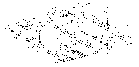
A third overpack configuration in accordance with the invention is shown in
FIG. 16.
The overpack configuration of FIG. 16 includes end cap overpack cartons 300
and 302 latched
around opposite end portions of primary shipping case 12 and an intermediate
overpach carton
310 latched around an intermediate portion of primary shipping case 12. The
end cap
overpack cartons 300 and 302 may be constructed as described above in
connection with
FIGs. 1 1-14B or FIGS. 15A-15C. Intermediate overpack carton 310 may be a
short version of
CA 02386216 2002-04-03
WO 01/25114 -1 1- PCT/US00/27622
the full-length overpack carton shown in FIGS. 1-SB and described above. It
will be
understood that both the end cap overpack cartons 300 and 302 and the
intermediate overpack
carton 310 may have any convenient width. A wider intermediate overpack carton
312 is
shown in phantom is FIG. 16. The width of the overpack cartons depend on the
length of the
primary shipping case and the required coverage of primary shipping case 12 by
the combined
overpack cartons.
The overpack cartons described above have been designed for packaging an
elongated,
rectangular primary shipping case. It will be understood that the overpack
carton can be
configured for packaging a primary shipping case of any size, shape and form
factor. For
1 o example, the primary shipping case is not necessarily elongated and is not
necessarily
rectangular. Furthermore, the primary shipping case may have any number of
sides.
While there have been shown and described what are at present considered the
preferred embodiments of the present invention, it will be obvious to those
skilled in the art
that various changes and modifications may be made therein without departing
from the scope
of the invention as defined by the appended claims.