Note: Descriptions are shown in the official language in which they were submitted.
CA 02386405 2002-04-04
WO 00/20667 PCT/AU99/00858
1
APPARATUS AND METHOD FOR PROCESSING GREEN FIBROUS PLANT STALKS
The present invention relates to improvements in or relating to bast
crops, and more particularly but not exclusively to the processing of
Cannabis sativa, better known as hemp.
BACKGROUND OF THE INVENTION
Bast crops contain an inner core sometimes called a hard surrounded
by an outer fibrous layer. One such bast crop is hemp. Hemp has a number of
1o commercial uses due to the properties of its fibre, which include strength
and
resilience. The fibre which can be extracted from the outer fibrous layer of a
hemp stalk has a variety of uses and may be a constituent in the production
of paper, fibreboard and rope. Hemp fibre also has the capacity to replace
cotton as a component of textiles. With the likelihood of gradual relaxation
of
strict legislative controls over cultivation and processing, hemp is likely to
become increasingly attractive to farmers as a valuable cash crop.
The stalk of a hemp plant is generally of substantially circular
cross-section, having a fibrous outer layer or bast and an inner core or hard.
The fibre of the plant is generally the more valuable commodity, although
2o the hard has some uses. It is therefore desirable to separate the fibre
from the
hard to yield a value-added commodity.
The principal difficulty in processing hemp has been found to lie in
separating the fibre from the hard. This process is referred to herein as
decortication.
A number of proposals have been suggested for separating the fibre
from the hard. The principal category of decortication is mechanical
separation. Of the mechanical operations, traditionally scutching has been
the most widely used. Scutching involves manually beating the hemp stalk
until the hard is dislodged from the fibre. This is usually followed by a
3o manual mechanical stripping operation using a bladed scutching wheel to
strip the outer fibre away from the hued. As this method of decortication is
generally a manual operation, it can be very labour-intensive and
time-consuming and hence inefficient. Scutching has therefore not been
found suitable for large scale commercial processing of hemp.
Substitute Sheet
(Rule 26) RO/AU
CA 02386405 2002-04-04
WO 00/20667 PCT/AU99/00858
Other mechanical decortication methods include the use of
ultrasonics, which employ sound waves to generate vibrations to break the
bonds between fibre and hurd.
Processing of hemp in a similar manner to that of flax has also been
proposed. This method involves netting the hemp, drying and breaking the
solidified hurd until the fibre separates from the core. Again this method is
time consuming and not generally suited to large-scale commercial operation.
There have also been several attempts to develop a method for decortication
by processing freshly cut hemp stalks which method by passes the need for
1o time consuming treatment prior to separating hurd from the fibre. Patent
specification GB 1235387 is directed to the processing of green hemp where
each plant stalk is passed through rollers, the stalk is split and beaten
before
the hurd is removed while the stalk is passed between two conveyors. A
disadvantage of this method is that uncleaned stalks remain after the process.
Specification GB 2205865 treats plant stalks as soon as they are cut however,
the Kurd is removed from the stalk by crushing the stalks between cylinders.
Specifications GB 693833 and U.S. 5465464 describe methods of processing
which, while not requiring time consuming pretreatment of the raw material,
are not directed towards the processing of green or freshly cut plant stalks
2o particularly green hemp stalks.
None of such prior art methods is suited to broadacre production
involving both the harvesting of the hemp crop and efficiently separating the
bast from the hurd of the harvested stalk on a commercial scale.
Patent specification WO 97/45573, the disclosure of which is
incorporated herein by reference, describes a method and apparatus for
processing the green plant stalk of a bast chop. To encourage the separation
of
the hurd from the bast, the bonds between the fibre and the hurd are
ruptured. The stalk is then subsequently split and the exposed Kurd is
stripped from the bast by the abrasion of a toothed holler on the hurd. Bond
3o rupturing is effected by passing the green stalks between a complex series
of
counter-rotating pressing rollers, before the stalk is split and stripped of
the
hurd. This proposal is somewhat complex and requires significant power to
drive the hollers.
The present invention provides an effective alternative to the foregoing
proposals for the processing of a bast crop.
CA 02386405 2002-04-04
WO 00/20667 PCT/AU99/00858
SUMMARY OF THE INVENTION
The present invention accordingly provides, in one embodiment, a
method for processing a plant stalk having a fibrous outer part and an inner
hued, the method including the steps of:
splitting the stalk substantially longitudinally whereby to expose the
hard;
dividing the exposed hard into segments in a segmenting step; and
separating the fibre from the hard.
1o The present invention provides, in another embodiment, an apparatus
for processing a split plant stalk having a fibrous outer part and an inner
hard, said plant stalk being split substantially longitudinally whereby to
expose the hard. The apparatus includes:
segmenting means to divide the hued into segments, and
a separator to separate the fibre from the hard.
In a still further embodiment the present invention provides an
apparatus for processing a plant stalk having a fibrous outer part and an
inner
hued, the apparatus including a splitter for splitting the stalk substantially
longitudinally whereby to expose the hard and a decorticator according to
2o the present invention.
The present invention provides, in yet another embodiment, fibre
produced from the application of the method and/or the apparatus provided
by the present invention and in yet another embodiment, Kurd produced
from the application of the method and/or the apparatus provided by the
present invention.
A plant stalk to be processed according to processing methods and
apparatus of the present invention may be a hemp stalk. A particularly
preferred hemp is that of the genus Cannabis sativa L and species thereof.
Other plant stalks envisaged for processing in accordance with the present
invention, include Kenaf, Ramie, sugar cane and other bast crops.
A method according to the present invention may include the
additional step of observing the growth pattern of the hemp plant in the
field,
whereupon harvesting and decortication of the crop may be commenced at a
predetermined phase of growth of the plant.
CA 02386405 2002-04-04
WO 00/20667 PCT/AU99/00858
4
It has been observed that the strength of the bond between the fibre
and hurd varies at various stages of growth of the plant. In a preferred
embodiment, harvesting and decortication are commenced when the plant is
green, also known as freshly cut or fresh green. The fibre of the stalk
preferably remains sufficiently fine for textile use, that is to say, prior to
pollen formation. The hemp plant stalk may be harvested by cutting and
stripped of leaves using known methods. The hemp may be harvested at 50
to 80 days maturity and preferably before lignins form. Preferably the hemp
is harvested before the outer fibre thickens and most preferably before the
outer fibre forms bundles. Before the adhesives between the hurd and outer
fibres harden and most preferably at approximately 60 days maturity or just
prior to flowering are particularly preferred indicators of a suitable time to
harvest a large crop for use in accordance with the present invention. The cut
end of the plant stalk is referred to herein as the butt end.
For best results processing of the stalk is preferably commenced before
the adhesive between the fibrous outer layer and the inner core dries.
Normally this is within two hours of harvesting but preferably immediately
after harvesting. Most preferably processing commences not more than 15
minutes after harvesting. Commencement of processing within two minutes
of harvesting is particularly preferred.
An apparatus provided according to the present invention may further
include a flatterer.
The flatterer may include means for modifying the cross-section of a
plant stalk from a substantially circular cross-section to a substantially
elongate cross-section. The flatterer may be located upstream of the
decorticator and preferably upstream of the splitter.
In a preferred embodiment the flatterer includes at least one pair of
counter-rotating pressing rollers (entry rollers). Each roller may include a
cylindrical surface and an axis of rotational symmetry. The surface of each
3o roller is preferably rubbed or toothed without sharp edges on the nubs or
teeth. Each roller may rotate around its own axis of rotational symmetry. The
pressing rollers are separate from and opposed to each other. The separation
between the pressing rollers or nip, may be capable of modifying the cross-
section of a plant stalk from a generally circular cross-section to a
generally
elongate or oval cross-section. The elongate cross-section may be described
CA 02386405 2002-04-04
WO 00/20667 PCT/AU99/00858
as having a major axis at right angles to a minor axis, where the minor axis
is
shorter than the major axis.
The splitter includes means by which the plant stalk may be split
longitudinally. The splitter may be capable of splitting the stalk
substantially
5 along or parallel to, the major axis of the elongate cross-section.
Splitting the
stalk exposes the inner core or hard of the plant stalk. The splitter may
comprise a sharp edge blade or the like poised centrally between the entry
rollers. The action of the splitter may create two separated portions of split
plant stalk which can be directed into two separate streams for further
processing.
A splitter according to the present invention may co-operate with
guide means which may be adapted and arranged to guide plant stalks into a
position whereby the blade acts to split the stalk. Alternatively, the plant
stalks may pass directly from the entry rollers to the splitter without use of
a
guide. A split stalk may remain in one piece in which case the action of the
splitter allows access to the hard.
Sputters suitable for use in accordance with the present invention are
described in more detail in patent specification WO 97/45573, the disclosure
of which is incorporated by cross-reference into the present specification.
2o In another preferred embodiment a directing means, adjacent to the
splitter, is capable of directing one stream of a separated split stalk into a
first
decorticator and the other stream of the stalk away from the first stream and
preferably into a second decorticator operating in parallel with the first
decorticator.
A decorticator provided in accordance with the present invention may
include segmenting means and a separator.
The segmenting means may be located upstream of the separator. The
separator may be capable of sweeping the segmented hued away from the
fibrous outer layer, thereby separating the hard from the fibre. The separator
may include a guide and a separating roller.
The segmenting means may include braking means and a conditioner.
The segmenting means may be capable of restraining the stalk so that the
separating roller can rotate at a speed faster than the speed of travel of a
stalk
through the segmenting means whereby to sweep the stalk and thereby
separate the hued from the fibre.
CA 02386405 2002-04-04
WO 00/20667 PCT/AU99/00858
6
The braking means may include a first roller. The first roller may
include a cylindrical surface and an axis of rotational symmetry. The first
roller may have a smooth or profiled surface. In a preferred embodiment, the
first roller has a smooth profiled surface. Alternatively, the braking means
may have a toothed profiled surface. The toothed profile surface may include
equally spaced ridges extending substantially the length of the first roller.
The first roller may rotate about its axis of rotational symmetry. The first ,
roller may be a free to rotate about its axis or it may be driven about its
axis
by driving means.
The braking means may be arranged to co-operate with a conditioner to
divide the hurd into segments, preferably without damaging the fibre. In one
preferred embodiment the conditioner includes means for dividing the hued
into segments. The means may be in the form of a toothed profiled surface.
The profiled surface of the conditioner may be capable of segmenting the
hued when used in co-operation with the braking means. The profiled surface
may be in the form of a profiled cylindrical surface. The surface may
comprise the surface of a second roller. The roller may have an axis of
rotational symmetry. The second roller carrying such a profiled cylindrical
surface is preferably capable of rotating about its axis of rotational
symmetry.
The second roller may be driven to rotate at a rate of up to 4000 rpm.
In a preferred embodiment, the roller is driven to rotate at a rate of between
2700 and 3100 rpm, most preferably at above 3000 rpm. The toothed profile
surface may include equally spaced ridges extending substantially the length
of the roller. The profiled surface of the conditioner may co-operate with the
braking means to divide the hued into segments. The conditioner and braking
means are preferably set apart to accommodate the outer fibrous layer only so
that the tips of the teeth of the conditioner penetrate the soft pith of the
stalk
against the braking means without cutting the outer fibrous layer so as to
divide the soft pit or hurd into segments.
In a preferred embodiment the braking means and the conditioner are
in the form respectively of a first roller and second roller. Said rollers may
be
separate from and opposed to one another. The first roller and second roller
may co-operate by counter-rotating. Preferably the braking means is a smooth
surfaced anvil roller and the conditioner is a toothed roller. Where both the
first and second rollers have a toothed profile the toothed profiled surface
of
the first roller and toothed profiled surface of the second roller
CA 02386405 2002-04-04
WO 00/20667 PCT/AU99/00858
7
counter-rotate, preferably without interdigitation. The separation or nip
between the first roller and second roller may approximate the thickness of
the outer fibre layer or bast of the plant stalk. Preferably this separation
is
between 0.1 to 0.6mm and most preferably between 0.25 to 0.38mm.
The first and second rollers may be driven to rotate at the same speed
as one another.
The arrangement is preferably such that the braking means and the.
conditioner co-operate to direct a stalk being processed toward the separator.
In a particularly preferred arrangement the braking means and the
1o conditioner are in the form of counter-rotating rollers with a plant stalk
entering the nip of the rollers being urged toward the separator as it emerges
from the nip. In this arrangement the braking means may be effective to
brake the speed of travel of the stalk as it enters the separator.
The guide of a separator provided in accordance with the present
invention may be located upstream from the separating roller. The guide may
comprise a presenting means also referred to herein as a hump for presenting
the plant stalk to the separating roller. The guide may further include a tail
extending from the hump in a direction generally parallel to the direction of
travel of the surface of the separating roller. The surface of the tail which
2o faces the surface of the separating roller comprises a work face. The
separation or gap between the closest portion of the operating surface of the
separating roller and the work face may be comparable to the size of the nip
between the braking means and the conditioner. The gap is preferably of a
size which is close to the thickness of the outer fibre layer or base of the
plant stalk. Preferably the gap is between 0.1 to 0.6mm and most preferably
between 0.25 to 0.38mm. The work face may be downstream of the hump. In
a preferred embodiment, the hump and the work face are integral units of the
guide.
The guide may include a guiding fence adapted to guide the separated
3o stalk toward the hump. The guide fence may be pivoted.
The hump may be fixed relative to the separating roller. Alternatively,
the hump may be moveable relative to the separating roller. In a particularly
preferred alternative embodiment, the hump and extending tail is in the form
of a pivoted arcuate member, which may be resiliently poised with respect to
the separating roller. In this embodiment, the hump is adjustably limited to
maintain a gap between the arcuate member and the separating roller to
CA 02386405 2002-04-04
WO 00/20667 PCT/AU99/00858
8
accommodate the fibre thickness gauge whilst the resilient bias maintains
the working pressure for a multiplicity of stalks. Preferably the pivoted hump
arrangement also includes a pivoted guiding fence upstream of the hump for
guiding the stalk portion to the gap between the hump and the separating
roller.
The separating roller may include a profiled cylindrical surface and an
axis of rotational symmetry. The profiled cylindrical surface may be effective
for sweeping the hued from the fibre. In a preferred embodiment, the
separating roller has a toothed profiled surface. The toothed profiled surface
includes equally spaced ridges extending substantially the length of the axis.
In another preferred embodiment the width of the ridges of the separating
roller is 0.5 mm. The separating roller may rotate about its axis of
rotational
symmetry. The separating roller may be driven about this axis by a driving
means.
The separating roller may rotate in the same direction as the second
roller. The circumferential speed of the separating roller, Vs, is the speed
[tangential velocity] of a point on the surface of the separating roller. The
circumferential speed of the second roller, V~ is the speed [tangential
velocity] of a point on the surface of the second roller. The separating
roller
may be driven about its rotational axis of symmetry at a rate where Vs is
between 1.3 V~ and 3 V~, preferably 2 ~ 0.5 V~. ,
The components of a decorticator provided in accordance with the
present invention may be mounted in a casing. The casing may include a pair
of opposed side walls. The components in the form of one or more rollers
including the braking means, the conditioner and the separating roller may
be journalled for rotation about an axle. The axle may be carried by the
casing. The axle may comprise a unit adapted such as by the provision of a
key way for rotation with the corresponding roller. Alternatively the roller
may be free to rotate relative to the axle. As will be appreciated by the man
skilled in the art, the exact arrangement is dependent upon the nature of the
drive train selected.
Components such as the guide of the separator also may be mounted in
the casing. Preferably the guide is mounted on at least one wall of the
casing.
Most Preferably the guide is adjustably mounted so that the gap between the
work face and the separating roller can be adjusted.
CA 02386405 2002-04-04
WO 00/20667 PCT/AU99/00858
9
In a particularly preferred arrangement the rollers comprising the
braking means, the conditioner and the separating roller are each fixedly
mounted on an axle which extends beyond the casing and includes means for
driving the respective axles whereby to drive the braking means, the
conditioner and the separating roller. The driving means may be in the form
of one or more belts from a remote drive shaft. In a particularly preferred
arrangement a gear train is provided so as to control the relative rotation
speeds of the braking means, the conditioner and the separating roller. The
gear train may include one or more gears co-operable with an external drive
1o whereby to drive the rotation of the braking means, the conditioner and the
separating roller.
In a particularly preferred arrangement a drive shaft is used which is
not mounted on the casing but operably engages a drive train mounted on the
casing whereby the casing and hence the decorticator according to the
present invention can be readily removed from the drive shaft for
maintenance, cleaning and the like.
The present invention also provides a method for processing a plant
stalk which includes splitting the stalk substantially longitudinally to
expose
the hard, dividing the exposed hard into segments and separating the fibre
2o from the hued. The splitting step may be conducted up stream of the
decorticator provided in accordance with another embodiment of the
invention. The split stalk may be fed to the decorticator by insertion of the
split stalk in the nip between the braking means and the conditioner. In the
preferred arrangement where the braking means has a substantially smooth
cylindrical surface and the conditioner has a substantially toothed outer
surface, the split stalk is preferably presented so that the fibrous outer
part
faces toward the smooth cylindrical surface of the braking means and the
exposed hard toward the toothed conditioner.
The minimum clearance in the nip between the teeth of the
3o conditioner and the surface of the braking means is preferably adjustable
so
as to correspond approximately to the thickness of the outer fibre layer. In
this arrangement as the split stalk passes through the nip, the teeth of the
conditioner divide the hued into segments which correspond approximately
to the spacing between the teeth on the conditioner. If the nip is too narrow
some of the fibres may be severed and if the nip is significantly greater than
CA 02386405 2002-04-04
WO 00/20667 PCT/AU99/00858
the width of the fibre layer, the hard may not be sufficiently segmented as it
passes between the braking means and the conditioner.
On exiting the segmenting step the split and segmented stalk is urged
by the rotation of the separating roller to travel between the separating
roller
5 and the work face. To enter the gap between the work face and the separating
roller the stalk passes over the hump. The hump is preferably in the form of a
smooth surface which acts to further expose the hard and present the
segments to the teeth of the separating roller. The action of the separating
roller to sweep the segmented Kurd from the fibre results from the speed of
1o the separating roller which is travelling at a circumferential speed
significantly greater than the speed of travel of the stalk as it passes
through
the conditioner. Thus the braking means is effective to restrain the speed of
travel of the stalk and thereby and allow the separating roller to effectively
sweep the segmented hard from the fibrous outer layer and thereby separate
the fibre from the hard.
When the hard is separated from the fibrous outer layer, it may fall
between the conditioner and the separating roller and hence out of the
decorticator as it passes over the hump. In an alternative path some of the
hard segments may be swept by the speed of the separating roller past the
2o fibrous outer layer and through the gap to exit the decorticator downstream
of the work face. The fibre may be ejected from the decorticator downstream
of the separator. The fibre and hard may be collected for later use.
In yet a further embodiment the present invention provides an
apparatus for processing a plant stalk, the stalk having an outer fibrous part
and an inner hued, wherein one side of the apparatus is at least partially
open, the apparatus including:
(a) separation means capable of separating the stalk substantially
longitudinally thereof to provide separated stalk components;
(b) means for delivering the stalk to the separation means;
(c) a conditioning section including conditioning means for each
separated stalk component, each conditioning means including a conditioner
roller and an associated conditioning workface;
(d) a decortication section for separating the core from the fibres including
decortication means for each conditioned stalk component, each
decortication means including a decorticating roller and an associated
decorticating workface; and
CA 02386405 2002-04-04
WO 00/20667 PCT/AU99/00858
11
(e) means for providing an air flow in the device, the air flow being such
as to entrain at least part of the separated core and transporting the
separated
core through the at least partially open side to remove the separated core
from the device.
The delivery means may be a set of entry rollers. Preferably the entry
rollers have projections at the periphery thereof. The entry rollers may be
self-adjusting and self-centring and arranged to come no closer than the
diameter of the smallest acceptable stalk. The bearings of each of the roller
shafts may be mounted bearing plates which pivot about a rotating idler
shaft. This rotation of the pivot shaft has the advantage of eliminating wear
from a critical area and reduces friction markedly. The linkage to the bearing
plates ensures that the stalks are kept centred and the spring provides
adjustable grip on the stalk.
The conditioning section of the device of the invention may include a
set of anvil rollers or the like located between the delivery means and the
conditioner rollers. The anvil rollers may be of the same diameter as the
conditioner rollers, although this is not essential. The anvil rollers may be
adjustable to suit various crop thicknesses. For example, the adjustment may
be achieved by replacement of the anvil rollers with rollers of a different
2o diameter. Preferably the anvil rollers have a smooth surface.
Each anvil roller is preferably associated with scraper means having a
very small clearance between it and the anvil roller. The scraper means may
be associated with a workface. Preferably each scraper means is associated
with a high velocity airflow between each anvil roller and its associated
scraper means to prevent the fibre from wrapping around the anvils and to
ensure that fibre and core are conveyed to the workface.
The conditioning and anvil rollers may move with the same surface
velocity.
The conditioner rollers and their associated workfaces serve to
separate the hurd into short pieces or segments. The conditioner rollers may
have outward projections such as teeth, blades, ridges or the like. Preferably
the projections are teeth the shape of which is selected to avoid damage to
the bast fibre and to keep power consumed to a minimum.
The decorticating rollers preferably move at a greater peripheral speed
than that of the conditioning and anvil rollers. Most preferably, the
CA 02386405 2002-04-04
WO 00/20667 PCT/AU99/00858
12
decorticating rollers move at about twice the peripheral speed of the
conditioning and anvil rollers.
The conditioning workface and the decorticator workface may be
separate or form part of the one body. The workfaces may be fixed. Each
workface may include an arcuate face which is concentric with its respective
roller to provide a substantially arcuate path for the stalk component to
follow whilst being conditioned by a conditioner roller or when undergoing
decortication by a decortication roller. The axis of each decorticating
roller/workface is placed relative to the axis of the respective conditioner
1o roller/first workface to provide a tortuous or serpentine path along which
the
stem component travels when passing through the conditioning and
decorticator sections.
The transition between the conditioning and decorticating workfaces
may be provided by a convex projection or hump at the cusp formed at the
15 intersection of the two workfaces. The purpose of the hump is to cause the
separation of the core from the bast fibre. By appropriate selection of the
curvature of the hump, the separation of the hurd from the bast can be
achieved in the most effective manner at the lowest power.
The workface(s) may be sprung inwardly at an adjustable pressure to
2o control the amount of pressure between the workface and its adjacent
roller.
The workface(s) may also be pivoted so that the workface can be lifted up to
allow ease of cleaning and maintenance.
Preferably all rollers are supported and driven at one end. Preferably
one end of each roller is left open and uncluttered to permit core escape
25 through entrainment in the air flow and to allow simple access for
maintenance. The rollers may be driven by hydraulic or pneumatic means.
The driving means may form part of the device or the device may include
means enabling it to be connected to a source of power.
The device may include a vacuum extraction arrangement for
30 extraction of core after it leaves the decorticator.
The separation means may be a knife, splitter blade, saw or any other
means capable of separating the stalk longitudinally thereof. Preferably the
separation means is fixed.
A particular problem associated with the processing of bast fibre plants
35 is that the bast fibre wraps around the shafts of the rollers. In a
preferred
form, the device of the present invention provides a solution to this problem
CA 02386405 2002-04-04
WO 00/20667 PCT/AU99/00858
13
by including in the device one or more guard means to prevent fibre
wrapping around the shaft of the rollers. Preferably the guard means is/are
one or more thread guard plates.
Preferably the means for providing air flow provides high velocity air
flow to the device. The means for providing air flow to the device may be one
or more jets and/or ducts or the like associated with, or capable of being
associated with, a source of air. The means for providing air flow may be one
or more gaps between components of the device. For example, the means
providing air flow may be the gap between the thread guards) and the shaft
of one or more rollers. The provision of air flow via the thread guard gap has
the added advantage of preventing loose fibres, plant liquids and particles
from entering the gap of the thread guard. Alternatively the air flow may be
provided via the gap between each scraper means and its associated anvil.
The latter option has the further benefit of preventing loose fibres from
wrapping around the anvils. The means for providing air flow may be a
combination of two or more of the means set out above.
The high velocity air jets may be provided from one or more ducts. The
high velocity air jets may be associated with the conditioning and/or
decorticating rollers. Preferably the high velocity air jets) are located so
that
it/they clear the conditioning and/or decorticating rollers of any fibres or
core
particles and/or keep the fibre moving where required. The jet of air expands
after it exits the workface. This jet expansion entrains surrounding fluid and
this draws the fibre towards the workface. The expanding jet also prevents
the fibre from actually contacting the workface. Moreover the entrainment
flow prevents the fibre from moving away from the workface and contacting
any other surfaces. Because the expanding jet has a velocity much higher
than the fibre velocity, this makes sure that the fibre does not decelerate
and
bunch up. It also facilitates downstream fibre handling.
The projections of the conditioning and/or decorticating rollers
3o preferably have apertures therethrough to permit the high velocity air to
pass
through the teeth and thereby eject any core. These holes also to provide a
parallel flow of air along the workface to keep the exiting fibre moving and
prevent its contact with any surface.
The parallel air flow along the workface section past the decorticating
roller may also be provided by air from one or more ducts within the
workface.
CA 02386405 2002-04-04
WO 00/20667 PCT/AU99/00858
14
The air jets may carry water droplets, mist or vapour to increase the
effect and control moisture content. Release agents such as hemp oil or
linseed oil may be added to the air to avoid sticking of the stalk component
to parts of the decorticator.
The source of air to the means for providing an air flow may form part
of the device of the present invention or it may be separate, in which case
the
device of the invention may include means for connection to such a source of
air. The source of air may be an air blower, compressor or the like.
The device of the invention may be associated with other components
1o for pre-processing the fibre for entry into the device, for example, a
primary
stripping stage to strip leaves and/or branches from the stalk. The device of
the invention may be associated with means for further processing of the
fibre produced by the device, for example chemical treatment means.
The device of the invention is suitable for use as a single component in
a fibre processing arrangement or a plurality of devices in accordance with
the invention may be incorporated into a processing system for parallel
processing of a plurality of stalks.
In a further aspect, the present invention provides a decorticating
module for decorticating a plant stalk having an outer fibrous layer and an
2o inner core, including:
(a) means for delivering a plant stalk to a separation means for separating
the stalk longitudinally thereof to halve the stalk;
(b) a conditioning section for each stalk half, the conditioning section
including toothed conditioner rollers and optionally smooth anvil rollers; and
(c) a decorticator section for each stalk half with stationary workfaces and
toothed decorticating rollers moving at a peripheral speed greater than that
of
the conditioner and anvil rollers; the module further including one or more
of the following:
(d) thread guard means having one or more gaps for preventing fibres from
wrapping around shafts of the rollers;
(e) high velocity air flow through the thread guard gaps) to prevent loose
fibres, plant material and/or particles from entering the gap;
(f) scraper means with a very small clearance and high velocity air flow to
keep the fibres from wrapping around the anvils;
(g) high velocity air flows through holes in the conditioner and
decorticator roller teeth to eject any core;
CA 02386405 2002-04-04
WO 00/20667 PCT/AU99/00858
(h) one or more high velocity air jets to clear the conditioner and/or
decorticator rollers of any fibres or core particles and to keep the fibre
moving and to prevent its contact with any surface;
(i) a parallel air flow along the workface to keep exiting fibre moving and
5 to prevent its contact with any surface; and
(j) one end of one or more rollers, preferably all rollers, is/are open and
uncluttered to permit core escape and simple access to the module for
maintenance.
In a further aspect, the present invention provides a method for
10 treatment of a plant stalk, the method including use of an apparatus in
accordance with the invention.
BRIEF DESCRIPTION OF THE DRAWINGS
15 The present invention will now be described with reference to
particularly preferred embodiments in which:
Figure 1 is a schematic side view of a decorticator according to one
preferred embodiment of the present invention;
Figure 2 is a plan view of the apparatus shown in Figure 1 with the
2o guide removed for clarity;
Figure 3 is a schematic side view of a further embodiment of a
decorticator according to the present invention; and
Figure 4 is a further schematic side view showing the spring
arrangement of the embodiment shown in Figure 3.
Figure 5 is a top schematic view of the hump used in the embodiment
of Example 2.
Figure 6 is a schematic perspective view of the guiding fence used in
the embodiment of Example 2.
Fig. 7 is a plan view of yet a further embodiment of the present
3o invention; and
Fig. 8 is a side cross-sectional view of the device of Fig. 7 showing an
embodiment of a thread guard plate arrangement in accordance with the
invention.
CA 02386405 2002-04-04
WO 00/20667 PCT/AU99/00858
16
Example 1
Figure 1 and 2 illustrate one preferred embodiment of the present
invention. The decorticator 1 includes segmenting means 2, which includes
braking means or anvil 10 and conditioner 20. Decorticator 1 also includes
separator 3, which includes guide 30 and separating roller 40.
Braking means 10 includes an axis of rotational symmetry 11, shaft 12
and cylindrical surface 13.
Conditioner 20 includes axis of rotational symmetry 21, shaft 22,
profiled surface 23, ridges 24 and spacings 25. Conditioner 20 is driven by a
1o driving means associated with drive shaft 22.
The braking means may be driven by a driving means associated with
drive shaft 12. The driving means is preferably in the form of a gear train
(not
shown) in which shafts 12, 22 and 42 mounted on casing 4 act as axles
carrying gears which are driven by an external drive shaft carrying a drive
gear to engage with the gears mounted on one or more of the axles
comprising shafts 12, Z2 and 4Z whereby to drive braking means 10,
conditioner 20 and separating roller 40.
The separation or nip 26 between braking means 10 and the
conditioner 20 is close to the value of the thickness of the fibrous outer
layer
2o of the plant stalk. Preferably this value is between 0.1 mm to 0.6 mm. Most
preferably this is between 0.25 mm to 0.38 mm.
In operation the plant stalk, which is preferably harvested after 60 days
maturity, just prior to flowering the plant, may be passed through a flatterer
to elongate the cross-section of the stalk.
The stalk may be then passed through a splitter which splits the stalk
longitudinally along the major axis of the elongate cross-section of the plant
stalk. The stalk may be split into separate parts thereby creating two streams
of split plant stalk and exposing the hurd.
One stream of the plant stalk is directed into decorticator 1 and the
other stream of the split plant stalk may be directed away from the first
stream, preferably into a second decorticator (not shown), operating in
parallel with decorticator 1.
The split plant stalk enters decorticator 1 at region 5 before passing
through the nip 26 of braking means 10 and conditioner 20. The stalks are
preferably straight and are led into nip 26 by the butt end.
CA 02386405 2002-04-04
WO 00/2066? PCT/AU99/00858
17
The split stalk preferably is orientated to enter decorticator 1 in a
position such that the fibrous outer layer of the split plant stalk lies
adjacent
cylindrical surface 13 of braking means 10 and the hard lies adjacent the
profiled cylindrical surface 23 of the conditioner 20.
Braking means 10 and conditioner 20 counter-rotate to urge a stalk
entering the nip to travel towards separating roller 40. Conditioner 20 may
rotate at a rate of up to 4000 rpm, preferably between 2700 rpm and 3100 .
rpm, and most preferably at 3000 rpm.
Ridges 24 of conditioner 20 divide the hard of the split plant stalk into
segments as it passes through the nip 20 of braking means 10 and conditioner
20.
After it emerges from segmenting means 2, the split plant stalk is
presented to separating roller 40 and guided between work face 32 and the
profiled surface 43 of the separating roller by hump 31.
Separating roller 40 includes an axis of rotation 41, shaft 42, profiled
surface 43, ridges 44 and spaces 45.
Separating roller 40 sweeps the split plant stalk against work face 32,
separating hard segments from the fibrous outer layer using ridges 44.
Separating roller 40 is driven by a driving means associated with axle
42 as described above.
In operation, the circumferential speed of the separating roller 40 V5. is
between 1.3 and 3 V~, the circumferential speed of conditioner 20. Preferably,
the circumferential speed VS of the separating roller 40 is 2~ 0.5 V~, The
circumferential speed of the conditioner 20 is V~.
Freshly harvested hemp processed according to the present invention
separates more efficiently into fibrous ribbons and hard than hemp in which
glue between the fibrous layer and Kurd has begun to dry. As the hemp dries,
more power is required to strip the hard from the stalk as the glue between
the fibrous outer layer and the inner hued begins to dry. vllhen the hard is
3o separated from the fibrous outer layer, it may fall in a region 6 between
conditioner 20 and separating roller 40 and hence out of the decorticator.
Separating roller 40 ejects the fibrous outer layer out of the
decorticator through region 7. The fibre may be ejected in ribbons which can
be roll baled, square baled, aligned, set in boxes or whatever the user
requires. ~Nhen the glue begins to dry, hard may be ejected past separating
roller 40. The hard may be easily separated from the fibre by collecting the
CA 02386405 2002-04-04
WO 00/20667 PCT/AU99/00858
18
product over water. The Kurd will float while the fibre sinks. The hurd may
be collected in boxes and used as a component for particle board, kitty
litter,
garden mulch, animal bedding, masonite or used in the making of ethanol.
The fibre may be collected and used as a component of textiles or as a
natural fibre.
Example 2
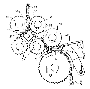
An alternative embodiment of the present invention is shown in Fig. 3.
The decorticator has twin entry rollers 50 having smoothly formed nubs 52
1o around the periphery thereof to elongate the cross-section of the stalk 90
and
to drive it undamaged over a knife splitter 54 poised centrally between the
entry rollers to form two split stalk portions 92. Each split stalk portion 92
passes to the nip of counter-rotating externally fluted conditioner 56 and
smooth surfaced anvil 58. The conditioner and anvil are set apart to
accommodate the fibrous outer layer only so that the tips of the conditioner
readily penetrate the soft pith of the stalk against the hard anvil without
cutting the outer fibrous layer so as to divide the soft pith or hurd into
segments.
The travelling conditioned split fibre is then guided by a guiding fence
60, pivoted at 70, to the variable region 67 of arcuate hump 64 so that the
fibre passes over the leading edge 62 and is violently swept between the
inner surface 69 of the hump and the teeth of decorticator 80 to thrash out
the pith or Kurd 94 free of fibre into a delivery area below. The leading edge
62 provides a more aggressive change of direction of the conditioned split
fibre than is achieved by the hump arrangement used in Example 1 described
above.
The arcuate hump 64 is adjustably limited to maintain an
accommodating gap 67 dependent on the fibre thickness gauge. In this
embodiment, the entrance to the hump region will not be closer than ten
3o thousandths of an inch. This is achieved by pivoting the hump at 68 and
adjustably spring loading the hump so as to maintain a working pressure for a
multiplicity of stalks. As best ShOWIl lIl Figs. 4, 5 and 6, the hump 64 is
resiliently biased toward the decorticator 80 by a bank of springs 110
pivotally mounted at 112. The springs pass through apertures 111 in the
guiding fence 60 and sit over projections 122 on the top surface of the hump
64.
CA 02386405 2002-04-04
WO 00/20667 PCT/AU99/00858
19
It is envisaged that the apparatus described herein may operate
independently or in combination with known harvesting apparatus, such as
the harvesting apparatus described in WO 97/45573 incorporated herein by
reference. The apparatus of the present invention may also be operated in
combination with known post processing means for the fibre product or bast
and hurd.
Example 3
Referring to Figure 7, the device 210 has an entry section 2, a
conditioning section 5, and decorticator section 7.
The direction of movement of a stalk through the device is shown by
arrow 100. The entry section 2 includes two counter-rotating entry rollers
211a, 211b which deliver a stalk (not shown) to fixed splitter blade 213
which splits the incoming stalk longitudinally in half. The entry rollers
211a,
211b are pivoted around point 15 which is the position of an idler shaft (not
shown). The entry section also includes air ducts 9 having reverse flow jets
Zl7a, 217b of 0.5 radii on the inside and no radii/chamfer on the outside
thereof. These jets are designed to provide approximately 50-150 m/s reverse
air flow onto the entry rollers 211a, 211b.
The device includes workfaces Zl9a, 219b, which are pivoted for easy
cleaning. The workfaces are also sprung inwardly at adjustable pressure to
control the amount of pressure between the workface and the rollers.
Counter-rotating anvil rollers 225a, 225b which rotate at approximately
4,000 rpm are provided between the entry rollers and the counter-rotating
conditioner rollers 221a, 221b. The anvil rollers are readily replaceable to
vary the clearance 240 in the range of about 0.2 to 0.5 mm. Each anvil roller
has an associated scraper (227a, 227b) provided with a supply of high
velocity air between each scraper and its respective anvil. Each scraper is
positioned about 50~m from its associated anvil roller.
Conditioner rollers 221a, 221b have teeth 229. Each tooth has a hole
230 of approximately 1-5mm diameter at an axial spacing of 5mm to allow
high velocity air flow through the teeth to allow hurd to be dislodged
therefrom. That part of the workface in the conditioning section has a face
that is coaxial with its associated conditioner roller.
CA 02386405 2002-04-04
WO 00/20667 PCT/AU99/00858
The workface in the conditioning section is substantially coaxial with
its associated conditioner roller. The transition between the conditioning
workface and the decorticator workface is provided by a hump 231.
Air duct 232 with air jets 233 is positioned in the conditioning section
5 to provide a high velocity air jet (greater than about 100 m/s) towards the
two
conditioner rollers. This air jet passes through the holes 230 in the teeth of
the conditioner rollers.
The decorticating rollers 223a, 223b have teeth 224 with holes 226
therethrough to allow passage of high velocity air through the teeth.
1o The decorticating rollers run at a peripheral speed approximately two
times that of the conditioner rollers, and in this case, run at approximately
8,000 rpm.
The decorticator section also includes an air duct 228 with high
velocity air jets 231 to provide high velocity air at a rate of 100-150 m/s.
15 Further air ducts 233 provide co-flowing air jets at approximately 30-80
m/s
to ensure that the bast fibre touches nothing and is attracted towards the co-
flowing jet.
All air ducts in the device are supplied with air through the thread
guard.
2o The rollers of the entry, conditioning and decorticator section are all
driven at the end on the same side. The other side of the device is open and
unobstructed to allow the high velocity air to escape from the top of the
device and taking entrained hard and loose fibres with it thereby clearing the
device of hard particles.
The rollers in each section are cantilevered gear duven rollers. All
rollers are driven through a thread guard plate 290 which prevents fibre wrap
around. High velocity air flow is provided through the thread guard gap to
prevent loose fibres, plant liquids and particles from entering the gap.
A suitable thread guard arrangement is shown in Figure 8. Roller 200
3o passes through thread guard plate 302, the gap 306 between the periphery of
the roller and the thread guard plate being sufficient to allow air flow
through the gap. Shaft 310 of the roller passes through an oil separation
plate
320 and bearing plate 330. The gap 322 between the shaft and the oil
separation plate is sufficient to allow air flow through the gap. The shaft is
supported on the bearing plate by bearing 332. An oil flinger 360 is provided
on the shaft.
CA 02386405 2002-04-04
WO 00/20667 PCT/AU99/00858
21
A source of air (not shown) provides air flow 370 between the thread
guard plate and the oil separation plate which in turn results in an air flow
through gaps 306 and 322. The air flow through thread guard gap 306
prevents fibres and other material from entering the gap. The air flow
through gap 322 prevents oil mist from escaping from the gear box 380 and
the bearings.
In operation, a hemp plant stalk is fed along direction 9 through entry
rollers at 311a, 311b which deliver the stalk to fixed splitter blade 213. The
splitter blade splits the stalk longitudinally through the core to produce two
1o stalk halves. Each stalk half moves toward the conditioning section,
passing
around the anvil to a conditioner roller which separates the hard into short
pieces. The conditioning and anvil rollers move with the same surface
velocity. The shape of the teeth of the conditioner rollers is selected to
avoid
damage to the bast fibre and to keep power consumed to a minimum.
The workface mounted scrapers 327a, 327b, and the air flow between
the anvil and the scraper both ensure that the bast fibre and the hard are
conveyed to the convex hump 331. The curvature of the hump is selected to
ensure that the separation of the hard from the bast fibre is most effective
with the lowest power.
The peripheral speed of the decorticating rollers is greater than the
conditioner rollers. A ratio of about 2:1 is used although this is to some
extent arbitrary, but has been found to work well. The conditioned fibre then
passes around hump 331 to the decorticating roller (323a, 323b) which
separates the hued from the bast fibre.
The high velocity air jets supply high velocity air, optionally
containing water droplets, or vapour to increase the effect and control
moisture content, into the various sections of the device. A release agent
such as hemp oil or linseed oil may be added to the air to avoid sticking of
the stalk components to parts of the decorticator.
3o The parallel air flow along the workface section past the decorticating
roller is supplied with air from the ducts 233 in the workface. The jet of air
expands after it exits the workface and entrains surrounding fluid and draws
the fibre towards the workface. The expanding jet also prevents the fibre
from contacting the workface. The entrainment flow prevents fibre from
moving away from the workface and contacting any other surface. The
expanding jet has a velocity much higher than the fibre velocity and this
CA 02386405 2002-04-04
WO 00/20667 PCT/AU99/00858
22
ensures that the fibre does not decelerate and bunch up. It also facilitates
the
downstream fibre handling. The holes in the teeth of the conditioning and
decorticating rollers allow high velocity air to flow therethrough to eject
any
Kurd that may be lodged therein.
The high velocity air jets operate to clear the conditioning and the
decorticating rollers of any fibres/particles which are present and keep the
fibre moving as required.
The combined air flow from the air jets and gaps escapes from the
open top of the device taking with it entrained hurd pieces and any loose
1o fibre.
This particular embodiment of the device of the invention is capable of
sequentially processing about 5 stalks per second.
A decorticating system may include a plurality of apparatus in
accordance with the present invention.
It will be appreciated by persons skilled in the art that numerous
variations and/or modifications may be made to the invention as shown in
the specific embodiments without departing from the spirit or scope of the
invention as broadly described. The present embodiments are, therefore, to
be considered in all respects as illustrative and not restrictive.