Language selection

Search

Patent 2387347 Summary

Third-party information liability

Some of the information on this Web page has been provided by external sources. The Government of Canada is not responsible for the accuracy, reliability or currency of the information supplied by external sources. Users wishing to rely upon this information should consult directly with the source of the information. Content provided by external sources is not subject to official languages, privacy and accessibility requirements.

Claims and Abstract availability

Any discrepancies in the text and image of the Claims and Abstract are due to differing posting times. Text of the Claims and Abstract are posted:

  • At the time the application is open to public inspection;
  • At the time of issue of the patent (grant).
(12) Patent: (11) CA 2387347
(54) English Title: UPLIFT SPRING ASSEMBLY TO COMPENSATE FOR HULL DEFLECTION AT MAIN BEARING OF A MOORING TURRET
(54) French Title: ENSEMBLE DE RESSORT DE POUSSEE PERMETTANT DE COMPENSER LA DEFORMATION DE LA COQUE AU NIVEAU DU POINT D'APPUI PRINCIPAL D'UNE TOURELLE D'AMARRAGE
Status: Term Expired - Post Grant Beyond Limit
Bibliographic Data
(51) International Patent Classification (IPC):
  • B63B 21/00 (2006.01)
  • B63B 21/50 (2006.01)
(72) Inventors :
  • FONTENOT, WILLIAM L. (United States of America)
  • HOBDY, MILES A. (United States of America)
  • BOATMAN, L. TERRY (United States of America)
(73) Owners :
  • FMC TECHNOLOGIES, INC.
(71) Applicants :
  • FMC TECHNOLOGIES, INC. (United States of America)
(74) Agent: FINLAYSON & SINGLEHURST
(74) Associate agent:
(45) Issued: 2005-05-03
(86) PCT Filing Date: 2000-10-06
(87) Open to Public Inspection: 2001-04-12
Examination requested: 2002-03-27
Availability of licence: N/A
Dedicated to the Public: N/A
(25) Language of filing: English

Patent Cooperation Treaty (PCT): Yes
(86) PCT Filing Number: PCT/US2000/027519
(87) International Publication Number: WO 2001025078
(85) National Entry: 2002-03-27

(30) Application Priority Data:
Application No. Country/Territory Date
60/158,001 (United States of America) 1999-10-06

Abstracts

English Abstract


An uplift spring assembly to compensate for hull deflection at a main bearing
of a mooring turret is disclosed. Elastomeric
pads are used to react turret uplift because of their properties of large
deflections and resistance to cold weather. Tie rods
are provided to transmit the uplift loads into the elastomeric pads. The
elastomeric pads react the uplift loads in compression. The
assembly arrangement prevents the elastomeric pads from reacting tension
loads.


French Abstract

L'invention concerne un ensemble de ressort de poussée permettant de compenser la déformation de la coque au niveau du point d'appui principal d'une tourelle d'amarrage. Des coussinets élastomères sont utilisés pour réagir à la poussée de la tourelle grâce à leurs propriétés de grande déformation et de résistance au temps froid. Les barres d'accouplement permettent de transmettre les charges de poussée aux coussinets élastomères qui réagissent aux charges de poussée en compression. L'agencement de l'ensemble empêche que les coussinets élastomères ne soient soumis aux charges de traction.

Claims

Note: Claims are shown in the official language in which they were submitted.

WHAT IS CLAIMED IS:
1. An axial support arrangement (50) for a turret (22) which is rotatably
supported
on a vessel (12) comprising,
a support ring (16) mounted on said vessel (12);
a load applying ring (36) positioned outwardly of said turret (22) and
rotatably
coupled to said turret (22) at a position above said support ring (16);
a retaining plate (66) coupled to said support ring (16) at a position above
said
load applying ring (36);
an upper elastomeric pad (54) sandwiched between said load applying ring (36)
and said retaining plate (66), said upper elastomeric pad (54) being coupled,
arranged and
dimensioned in cooperation with said retaining plate (66) and said load
applying ring (36)
to be put in compression with relative upward motion of said turret (22) with
respect to
said vessel (12) but not be put in tension with relative downward motion of
said turret
(22) with respect to said vessel (12).
2. The arrangement (50) of claim 1 wherein,
said retaining plate (66) is coupled to said support ring (16) by a tie rod
(70) which
extends through a hole (17) in said support ring (16),
said upper elastomeric pad (54) is fixed to said retainer plate (66) and to
said load
applying ring (36), whereby with relative upward motion of said turret (22)
with respect
8

to said vessel (12), said upper elastomeric pad (54) is squeezed between said
retaining
plate (66) and said load applying ring (36), but with relative downward motion
of said
turret (22) with respect to said vessel (12), said upper elastomeric pad (54)
is prevented
from being placed in tension by sliding of said tie rod (70) through said hole
(17) in said
support ring (16) as said load support ring (36) moves downward with respect
to support
ring (16).
3. The arrangement of claim 1 wherein,
said retaining plate (66) is coupled to said support ring (16) by a tie rod
(70) which
extends through aligned holes in said retaining plate (66), said upper
elastomeric pad
(54), said load applying ring (36), and said support ring (16) and by nuts
(72), (74)
secured over said stud (70) above said retaining plate (66) and below said
support ring
(16).
4. The arrangement of claim 1, further comprising,
a lower elastomeric pad (52) sandwiched between said load applying ring (36)
and
said support ring (16),
said lower elastomeric pad (52) being coupled, arranged and dimensioned in
cooperation with said load applying ring (36) and said retaining plate (66) to
be put in
compression with relative downward motion of said turret (22) with respect to
said vessel
(12) but not be put in tension with relative upward movement of said turret
(22) with
respect to said vessel (12).
9

5. The arrangement of claim 4 wherein,
said lower elastomeric pad (52) is fixed axially relative to said load
applying ring
(36) but not to said support ring (16), whereby with relative downward motion
of said
turret (22) with respect to said vessel (12) said lower elastomeric pad (52)
is squeezed
between said support ring and said load applying ring (36), but with relative
upward
motion of said turret (22) with respect to said vessel (12), said lower
elastomeric pad (54)
stays fixed relative to said load applying ring (36) thereby preventing
tension in said
lower elastomeric pad (52).
6. The arrangement of claim 5 wherein,
said mounting plate (16) includes an annular ring (56) extending upwardly from
an upper side thereof, and said lower elastomeric pad (52) is arranged and
designed to
slide within said annular ring (56) whereby with relative downward motion of
said turret
(22) with respect to said vessel (12), said lower elastomeric pad (52) is
squeezed between
said load applying ring (36) and said retaining ring (16), but with relative
upward motion
of said turret (22) with said respect to said vessel (12), said lower
elastomeric pad (52)
is free to slide upwardly with respect to said annular ring (56).
7. An axial support arrangement (50) for a turret (22) which is rotatably
supported
on a vessel (12) comprising,
a support ring (16) mounted on said vessel (12);
10

a load applying ring (36) positioned about the outer periphery of said turret
(22)
and rotatably coupled to said turret (22) at a position above said support
ring (16);
a lower elastomeric pad (52) sandwiched between said load applying ring (36)
and
said support ring (16),
said lower elastomeric pad (52) being coupled, arranged and dimensioned in
cooperation with said load applying ring (36) and said retaining plate (66) to
be put in
compression with relative downward motion of said turret (22) with respect to
said vessel
(12) but not be put in tension with relative upward movement of said turret
(22) with
respect to said vessel (12).
8. The arrangement of claim 7 wherein,
said lower elastomeric pad (52) is fixed axially relative to said load
applying ring
(36) but not to said support ring (16), whereby with relative downward motion
of said
turret (22) with respect to said vessel (12) said lower elastomeric pad (52)
is squeezed
between said support ring and said load applying ring (36), but with relative
upward
motion of said turret (22) with respect to said vessel (12), said lower
elastomeric pad (54)
stays fined relative to said load applying ring (36) thereby preventing
tension in said
lower elastomeric pad (52).
9. The arrangement of claim 8 wherein,
said mounting plate (16) includes an annular ring (56) extending upwardly from
an upper side thereof, and said lower elastomeric pad (52) is arranged and
designed to
11

slide within said annular ring (56) whereby with relative downward motion of
said turret
(22) with respect to said vessel (12), said lower elastomeric pad (52) is
squeezed between
said load applying ring (36) and said retaining ring (16), but with relative
upward motion
of said turret (22) with said respect to said vessel (12), said lower
elastomeric pad (52)
is free to slide upwardly with respect to said annular ring (56).
10. The arrangement of claim 7 further comprising,
a retaining plate (66) coupled to said support ring (16) at a position above
said
load applying ring (36);
an upper elastomeric pad (54) is sandwiched between said retaining plate (66)
and
said load applying ring (36),
said retaining plate (66) is coupled to said support ring (16) by a tie rod
(70) which
extends through aligned holes in said retaining plate (66), said upper
elastomeric pad
(54), said load applying ring (36), said lower elastomeric pad (52), and said
support ring
(16) and by nuts (72), (74) secured over said stud (70) above said retaining
plate (66) and
below said support ring (16).
11. The arrangement of claim 10 wherein,
said upper elastomeric pad (54) is coupled, arranged and dimensioned in
cooperation with said retaining plate (66) and said load applying ring (36) to
be put in
compression with relative upward motion of said turret (22) with respect to
said vessel
12

(12) but not be put in tension with relative downward motion of said turret
(22) with
respect to said vessel (12).
12. The arrangement of claim 10 wherein,
said upper elastomeric pad (54) is fixed to said retainer plate (66) and to
said load
applying ring (36), and said retaining plate (66) is secured to said tie rod
(70), whereby
with relative upward motion of said turret (22) with respect to said vessel
(12), said upper
elastomeric pad (54) is squeezed between said retaining plate (66) and said
load applying
ring (36), but with relative downward motion of said turret (22) and said load
applying
ring (36) with respect to said vessel (12) and said mounting plate (16), said
upper
elastomeric pad (54) is prevented from being placed in tension because said
tie rod (70)
is free to slide with respect to said mounting plate (16).
13

Description

Note: Descriptions are shown in the official language in which they were submitted.


CA 02387347 2002-03-27
WO 01/25078 PCT/US00/27519
UPLIFT SPRING ASSEMBLY TO COMPENSATE FOR HULL
DEFLECTION AT MAIN BEARING OF A MOORING TURRET
BACKGROUND OF THE INVENTION
Field of the Invention
This invention relates to an uplift spring assembly for the main bearing of a
mooring turret to compensate for the hull deflection or distortion of the
moored vessel.
Description of the Prior Art
Heretofore, springs have been provided for supporting the upper bearing of a
mooring turret for a moored vessel. The mooring turret is usually mounted for
rotation
within a moon pool in the body or hull of the vessel. The vessel weathervanes
about the
turret which is anchored to the sea floor.
U.S. Patent No. 5,306,186 dated April 26, 1994 illustrates a mooring system
including a turret supported within a moon pool on a main upper bearing
mounted on the
hull of the moored vessel. An upper turret support ring on the body of the
vessel has a
plurality of elastomeric pads equally spaced about the outer periphery of the
turret for
absorbing vertical shocks between the turret and the vessel. The elastomeric
pads
function to minimize moment load imbalances between the turret and vessel, and
to
compensate for manufacturing tolerances of the upper bearing supports. The
elastomeric
pads are placed in compression upon downward movement of the turret relative
to the
body of the vessel.
1

CA 02387347 2002-03-27
WO 01/25078 PCT/US00/27519
Identification of Obiect of the Invention
A principal object of the invention is to provide an elastomeric spring
assembly
for the upper bearing of a mooring turret which includes a first elastomeric
spring which
is placed in compression upon an upward movement or uplifting of the turret
relative to
the vessel and a second elastomeric spring which is placed in compression upon
a
downward movement of the turret relative to the vessel.
SUMMARY OF THE INVENTION
The object identified above as well as other objects and features of the
invention
are provided in a spring assembly for the upper main bearing between a mooring
turret
and a vessel. An elastomeric spring is provided to react against turret uplift
loads and
downlift loads. A load applying horizontal ring connected to the main upper
bearing has
upper and lower elastomeric pads positioned on opposed sides thereof. A tie-
rod extends
through the load applying ring and the opposed elastomeric pads. The tie-rod
is anchored
at its lower end to a base support on the vessel. The upper end of the tie-rod
is anchored
to an upper retaining plate. Upon an upward or uplifting movement of the
turret, the tie-
rod is effective to prevent movement of the retaining plate for transmitting a
compressive
force against the upper elastomeric pad thereof to permit the absorbing of the
uplifting
force by compression of the upper elastomeric pad. The lower elastomeric pad
is
2

CA 02387347 2002-03-27
WO 01/25078 PCT/iJS00/27519
compressed against the base support on the vessel by the load applying ring
and is
effective to absorb a downward force from the turret and load applying ring.
BRIEF DESCRIPTION OF THE DRAWINGS
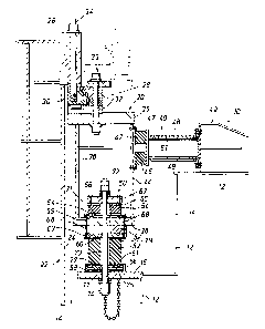
Figure 1 is a cross-sectional view of a spring assembly which embodies the
present
invention and which is positioned between the vessel and the upper main
bearing for a
turret mounted in a moon pool of the vessel.
DESCRIPTION OF THE INVENTION
Referring to Figure 1, a vessel shown at 10 has a hull 12 with a moon pool
generally indicated at 14 extending through the hull or body 12 of vessel 10.
A horizontal
base support ring 16 on hull 12 adjacent moon pool 14 is mounted on vessel
hull 12 and
supports a spring assembly generally indicated at 20 for turret 22 mounted
within moon
pool 14. Turret 22 is anchored to the sea floor by a plurality of mooring
lines or anchor
legs (not shown). The vessel 10 weatherwanes about turret 22 in a manner that
is well
known.
A plurality of spring assemblies 20, such as twenty, for example, are equally
spaced about the outer periphery 24 of turret 22. Figure 1 shows a single
spring assembly
according to the invention for illustration. Turret 22 includes an upper
turret shear
20 ring 26 which extends outwardly from the outer periphery 24 of turret 22.
Shear ring 26
3

CA 02387347 2002-03-27
WO 01/25078 PCT/US00/27519
supports turret 22 on a main upper bearing generally indicated at 28 which
includes an
inner ring 30 mounted on bearings within outer rings 32. Suitable studs 34
secure turret
shear ring 26 to inner bearing ring 30. Outer bearing rings 32 are secured by
studs 33 to
an upper load applying support ring 35 of spring assembly 20. Spring assembly
20
includes lower load applying support ring 36. Annular vertical member 38 is
secured
between load applying support rings 35 and 36. A flanged plate 44 is secured
between
support rings 35 and 36 at the position for each radial spring assembly 40
about the
periphery of the turret 22.
Spring assembly 20 includes a radial spring subassembly generally indicated at
40
mounted between an abutment 42 on hull 12 and a vertical member 44 secured
between
rings 35 and 36. Radial spring subassembly 40 includes an elastomeric pad 46
between
the flanged plate 44 and an opposed plate 47 and is adapted to absorb or
dampen radial
loads from turret 22. Telescoping cylinders 49, 51, which are slidable
relative to each
other, prevent tensioning of elastomeric pad 46.
Spring assembly 20 also includes a vertical uplift spring assembly shown
generally
at 50 which embodies this invention. Vertical uplift spring assembly 50 is
supported on
base support ring 16 of hull 12 adjacent moon pool 14. Assembly 50 includes a
lower
elastomeric pad 52 below a load applying ring 36 and an upper elastomeric pad
54 above
load applying ring 36.
4

CA 02387347 2002-03-27
WO 01/25078 PCT/US00/27519
A lower annular ring 56 extends upwardly from base plate support 16. Suitable
leveling plates or shims 58 including a layer of epoxy (if needed) are
positioned within
ring 56 for leveling spring assembly 50. A lower plate 75 is attached by bolts
61 to ring
77 of the lower elastomeric pad 52 and slides with pad 52 inside ring 56 to
prevent
application of tension in pad 52. An upper plate 63 is secured by bolts 79 to
ring 60 of
lower elastomeric pad 52. Metallic rings 60, 77 are molded into lower pad 52.
Metallic
rings 64, 65 are molded into upper pad 54. Bolts 68 secure upper plate 63 and
lower
elastomeric pad 52 to the load applying ring 36. Bolts 68 also secure ring 71
of the upper
elastomeric spring to load applying ring 36 as described below. A horse-shoe
shaped
spacer 62 is positioned between plate 60 and load applying ring 36 for in-
service
replacement of a single elastomeric pad 52.
Upper elastomeric pad 54 is secured by means of bolts 69 to a lower plate 71
via
ring 64 which is also secured to the vertical load applying ring 36 by bolts
68. Upper
elastomeric pad 54 has its molded ring 65 fixed to retaining plate 66 by bolts
67.
A central tie rod or threaded bolt 70 anchors vertical spring assembly 50 on
base
support ring 16 and vertical load applying ring 36. The upper end of tie rod
70 includes
a suitable nut 72 washers abutting above retaining plate 66. The lower end of
rod 70 has
a suitable nut 74 washers abutting beneath base support 16. Tie rod 70 is
arranged to
slide downwardly when ring 36 moves downwardly (with ring 66 and elastomeric
pad
54), through a hole 17 in plate 58 and ring 16. Thus, ring 66 is prevented
from moving
5

CA 02387347 2002-03-27
WO 01/25078 PCT/US00/27519
up more than a distance of the tie rod 70 between nuts 72, 74, yet ring 66 can
move down
with respect to ring 16 because rod 70 can slide down through hole 17. Ring 36
and ring
66 move down as a unit, but ring 36 can move upwardly with respect to ring 66.
Operation
Vertical spring subassembly 50 is operable upon relative downward movement of
turret 22 with respect to vessel 12 to compress lower elastomeric pad 52
between base
support plate 16 and load applying ring 36. Elastomeric pad 54 is not placed
in tension
during such downward movement of turret 22 and load applying ring 36 from the
neutral
position shown in Figure 1, because the tie rod 70 slides through a hole 17 in
base support
ring 16. Thus, lower elastomeric pad 52 is put in compression effective to
absorb or
dampen vertical loads exerted in a downward direction by turret 22 and load
applying
ring 36, while upper elastomeric pad 54, moving downwardly with load applying
ring 36
and retaining plate 66, is not placed in tension.
However, elastomeric pad 52 is not adapted to absorb any substantial upwardly
directed vertical or upli$ing loads. For this purpose, elastomeric pad 54 is
provided.
Upon relative upward movement of turret 22 with respect to vessel 12 from the
position
shown in Figure 1, upward movement of load applying ring 36 relative to base
support
16 and retaining plate 66 compresses elastomeric pad 54 between retaining
plate 66 and
load applying ring 36. Retaining plate 66 is held against upward movement by
nut 72 on
tie rod 70 anchored to support ring 16. Elastomeric pad 52 is not placed in
tension upon
6

CA 02387347 2002-03-27
WO 01/25078 PCT/US00/27519
upward movement of load applying ring 36 from the position of Figure 1,
because pad
52 is fixed to plate 36 by bolts 68 and plate 60, and because plate 75 slides
upwardly
within ring 56. The uplifting of turret 22 is transmitted by shear ring 26 to
inner bearing
ring 30, thence to outer bearing rings 32 and upper ring 35, and thence to
vertical
members 38, 44 and load applying ring 36 for exerting a compression load
against upper
elastomeric pad 54, and ultimately via plate 66 and tie rod 70 to support ring
16 on vessel
12.
From the above, an elastomeric spring assembly 50 has been provided in which
upwardly directed vertical or uplifting loads exerted by the turret are
absorbed or
cushioned by an elastomeric element 54. Downwardly exerted movements by the
turret
are absorbed or cushioned by an elastomeric element 52.
While a preferred embodiment of the present invention has been illustrated in
detail, it is apparent that modifications and adaptations of the preferred
embodiment will
occur to those skilled in the art. However, it is to be expressly understood
that such
modifications and adaptations are within the spirit and scope of the present
invention.
7

Representative Drawing
A single figure which represents the drawing illustrating the invention.
Administrative Status

2024-08-01:As part of the Next Generation Patents (NGP) transition, the Canadian Patents Database (CPD) now contains a more detailed Event History, which replicates the Event Log of our new back-office solution.

Please note that "Inactive:" events refers to events no longer in use in our new back-office solution.

For a clearer understanding of the status of the application/patent presented on this page, the site Disclaimer , as well as the definitions for Patent , Event History , Maintenance Fee  and Payment History  should be consulted.

Event History

Description Date
Inactive: Expired (new Act pat) 2020-10-06
Common Representative Appointed 2019-10-30
Inactive: IPC from MCD 2006-03-12
Grant by Issuance 2005-05-03
Inactive: Cover page published 2005-05-02
Pre-grant 2005-02-17
Inactive: Final fee received 2005-02-17
Notice of Allowance is Issued 2004-11-29
Letter Sent 2004-11-29
Notice of Allowance is Issued 2004-11-29
Inactive: Approved for allowance (AFA) 2004-11-08
Inactive: Acknowledgment of national entry - RFE 2002-10-25
Inactive: Cover page published 2002-09-24
Inactive: Office letter 2002-09-24
Letter Sent 2002-09-19
Inactive: Applicant deleted 2002-09-19
Inactive: First IPC assigned 2002-07-18
Application Received - PCT 2002-07-03
National Entry Requirements Determined Compliant 2002-03-27
Request for Examination Requirements Determined Compliant 2002-03-27
All Requirements for Examination Determined Compliant 2002-03-27
Application Published (Open to Public Inspection) 2001-04-12

Abandonment History

There is no abandonment history.

Maintenance Fee

The last payment was received on 2004-09-21

Note : If the full payment has not been received on or before the date indicated, a further fee may be required which may be one of the following

  • the reinstatement fee;
  • the late payment fee; or
  • additional fee to reverse deemed expiry.

Please refer to the CIPO Patent Fees web page to see all current fee amounts.

Owners on Record

Note: Records showing the ownership history in alphabetical order.

Current Owners on Record
FMC TECHNOLOGIES, INC.
Past Owners on Record
L. TERRY BOATMAN
MILES A. HOBDY
WILLIAM L. FONTENOT
Past Owners that do not appear in the "Owners on Record" listing will appear in other documentation within the application.
Documents

To view selected files, please enter reCAPTCHA code :


To view images, click a link in the Document Description column. To download the documents, select one or more checkboxes in the first column and then click the "Download Selected in PDF format (Zip Archive)" or the "Download Selected as Single PDF" button.

List of published and non-published patent-specific documents on the CPD .

If you have any difficulty accessing content, you can call the Client Service Centre at 1-866-997-1936 or send them an e-mail at CIPO Client Service Centre.


Document
Description 
Date
(yyyy-mm-dd) 
Number of pages   Size of Image (KB) 
Representative drawing 2002-03-27 1 31
Representative drawing 2002-07-18 1 14
Description 2002-03-27 7 255
Claims 2002-03-27 6 197
Abstract 2002-03-27 2 72
Drawings 2002-03-27 1 35
Cover Page 2002-09-24 1 46
Cover Page 2005-04-08 1 47
Acknowledgement of Request for Examination 2002-09-19 1 177
Reminder of maintenance fee due 2002-09-18 1 110
Courtesy - Certificate of registration (related document(s)) 2002-09-19 1 112
Notice of National Entry 2002-10-25 1 200
Commissioner's Notice - Application Found Allowable 2004-11-29 1 162
PCT 2002-03-27 4 157
Correspondence 2002-09-19 1 15
Correspondence 2005-02-17 1 30