Language selection

Search

Patent 2387478 Summary

Third-party information liability

Some of the information on this Web page has been provided by external sources. The Government of Canada is not responsible for the accuracy, reliability or currency of the information supplied by external sources. Users wishing to rely upon this information should consult directly with the source of the information. Content provided by external sources is not subject to official languages, privacy and accessibility requirements.

Claims and Abstract availability

Any discrepancies in the text and image of the Claims and Abstract are due to differing posting times. Text of the Claims and Abstract are posted:

  • At the time the application is open to public inspection;
  • At the time of issue of the patent (grant).
(12) Patent: (11) CA 2387478
(54) English Title: A MOLD TOOL AND METHOD FOR FORMING A TRIM COVERED FOAM SUBSTRATE OF A SEAT ASSEMBLY
(54) French Title: OUTIL A MOULURE ET PROCEDE DE FACONNAGE D'UN SUBSTRAT EN MOUSSE RECOUVERT D'UNE GARNITURE DE SIEGE
Status: Term Expired - Post Grant Beyond Limit
Bibliographic Data
(51) International Patent Classification (IPC):
  • B29C 63/02 (2006.01)
  • B29C 33/04 (2006.01)
  • B29C 44/14 (2006.01)
  • B29C 44/34 (2006.01)
  • B60N 2/70 (2006.01)
  • B60N 2/72 (2006.01)
(72) Inventors :
  • DEMOE, LARRY F. (Canada)
  • FLEUCHAUS, KURT (Canada)
  • KRESIN, JENS (Canada)
(73) Owners :
  • INTIER AUTOMOTIVE INC.
(71) Applicants :
  • INTIER AUTOMOTIVE INC. (Canada)
(74) Agent: JEFFREY T. IMAIIMAI, JEFFREY T.
(74) Associate agent:
(45) Issued: 2007-04-10
(86) PCT Filing Date: 2000-10-12
(87) Open to Public Inspection: 2001-04-19
Examination requested: 2005-09-13
Availability of licence: N/A
Dedicated to the Public: N/A
(25) Language of filing: English

Patent Cooperation Treaty (PCT): Yes
(86) PCT Filing Number: PCT/CA2000/001161
(87) International Publication Number: WO 2001026883
(85) National Entry: 2002-04-16

(30) Application Priority Data:
Application No. Country/Territory Date
60/158,955 (United States of America) 1999-10-12

Abstracts

English Abstract


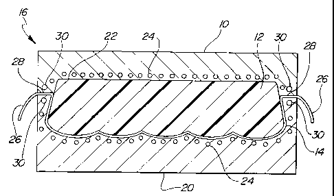
A mold tool (16) for forming a trim covered foam substrate of a seat assembly
comprises an upper mold cast (18)
defining an upper mold surface (19) and a lower mold cast (20) defining a
lower mold surface (2). A split line (28) is defined adjacent
to the upper and lower mold surfaces between the upper mold cast and the lower
mold cast when the mold casts are in facing mating
engagement forming a mold cavity (22) therebetween. A plurality of heat lines
(24) extend through the upper (18) and lower (19)
mold casts adjacent the respective upper and lower mold surfaces for heating
the mold cavity (22). A cooling line (30) extends
through at least one of the upper and lower mold casts adjacent the split line
(28) for cooling the split line of the mold tool.


French Abstract

L'invention concerne un outil à moulure (16) servant à façonner un substrat en mousse recouvert d'une garniture de siège. L'outil à moulure comprend un moule supérieur (18) délimitant une surface de moule supérieure (19), et un moule inférieur (20) délimitant une surface de moule inférieure (2). Une ligne de séparation (28) est formée entre le moule supérieur et le moule inférieur, à proximité des surfaces de moule supérieure et inférieure, si bien que, lorsque les moules en vis-à-vis sont en prise l'un avec l'autre, ils forment entre eux une cavité du moule (22). Plusieurs lignes de chauffage (24) s'étendent à travers les moules supérieure (18) et inférieure (20) et jouxtent les surfaces de moule supérieure et inférieure pour chauffer la cavité du moule (22). Une ligne de refroidissement (30) s'étend à travers au moins le moule supérieur ou inférieur et jouxte la ligne de séparation (28) de l'outil à moulure qu'elle refroidit.

Claims

Note: Claims are shown in the official language in which they were submitted.


What is claimed is:
1. A mold tool for forming a trim covered foam substrate of a seat assembly
comprising:
an upper mold cast defining an upper mold surface;
a lower mold cast defining a lower mold surface;
a split line defined adjacent to said upper and lower mold surfaces between
said
upper mold cast and said lower mold cast when said mold casts are in facing
mating
engagement forming a mold cavity therebetween;
a plurality of heat lines extending through at least one of said upper and
lower
mold casts adjacent said respective upper and lower mold surfaces for heating
said mold
cavity; and
a cooling line extending through at least one of said upper and lower mold
casts
adjacent said split line for cooling said split line of said mold tool.
2. A method of forming a trim covered foam substrate of a seat assembly
comprising the steps of:
providing an mold tool having an upper mold cast defining an upper mold
surface
and a lower mold cast defining a lower mold surface;
securing a trim cover onto the upper mold surface;
spraying urethane foam onto the lower mold surface;
moving the upper mold cast into facing mating engagement with the lower mold
cast to define a mold cavity therebetween;
extending a skirt portion of the trim cover through a split line defined
adjacent to
the upper and lower mold surface and between the upper and lower mold cast;
heating the mold cavity by circulating heated fluid through a plurality of
heat
lines within the upper and lower mold casts adjacent the respective upper and
lower mold
surfaces;
cooling the split line by circulating cooling fluid through a cooling line
within one
6

of the upper and lower mold cast adjacent the split line; and
curing the urethane foam to bond the trim cover thereto within the mold
cavity.
7

Description

Note: Descriptions are shown in the official language in which they were submitted.


CA 02387478 2002-04-16
WO 01/26883 PCT/CA00/01161
A MOLD TOOL AND METHOD FOR FORMING A TRIM COVERED
FOAM SUBSTRATE OF A SEAT ASSEMBLY
BACKGROUND OF THE INVENTION
1) Field of the Invention
The subject invention relates to a mold tool for forming a trim covered foam
substrate of a seat assembly.
2) Detailed Description of the Related Art
A vehicle seat is typically formed from a molded urethane foam substrate that
is
surrounded by a decorative trim cover. The manufacturing method includes
securing the
cover to an upper cast of a mold tool and spraying liquid urethane foam into a
lower cast
of a mold tool. The cover includes a skirt that protrudes through a split line
between the
first cast and the second cast when the two casts are in mating engagement.
The split line.
1 ~ and heat generated in the mold tool by heating lines, and by the
exothermic urethane
crosslinking reaction, disfigure the portion of the trim cover within the
split line. The
trim cover must be restored by the supplementary step of steaming the cover.
However,
often the cover can not be restored, particularly for less expensive, lower
quality covers.
Therefore. it is desirable to provide a mold tool and method that does not
cause
disfiguring damage to the trim cover and will improve manufacturing cycle time
and
enable the use of less expensive, lower quality covers.
SUMMARY OF THE INVENTION
2~ The subject invention relates to a mold tool for forming a trim covered
foam
substrate of a seat assembly. The mold tool comprises an upper mold cast
defining an
upper mold surface and a lower mold cast defining a lower mold surface. A
split line is
defined adjacent to the upper and lower mold surfaces between the upper mold
cast and
the lower mold cast when the mold casts are in facing mating engagement
forming a
1
SUBSTITUTE SHEET (RULE 26)

CA 02387478 2002-04-16
WO 01/26883 PCT/CA00/01161
mold cavity therebetween. A plurality of heat lines extend through at least
one of the
upper and lower mold casts adjacent the respective upper and lower mold
surfaces for
heating the mold cavity. A cooling line extends through at least one of the
upper and
lower mold casts adjacent the split line for cooling the split line of the
mold tool.
BRIEF DESCRIPTION OF THE DRAWINGS
Advantages of the present invention will be readily appreciated as the same
becomes better understood by reference to the following detailed description
when
considered in connection with the accompanying drawings wherein:
Figure 1 is a perspective view of a vehicle seat;
Figure 2 is a cross-sectional view of a vehicle seat mold tool having an upper
cast
and a lower cast: and
Figure 3 is a perspective view of the lower cast of the mold tool.
DETAILED DESCRIPTION OF THE PREFERRED EMBODIMENT
Referring to the Figures, wherein like numerals indicate like or corresponding
parts throughout the several views, a vehicle seat is generally shown at 10 in
Figure I .
The vehicle seat 10 includes a seat back 11 and a seat cushion 13. which are
typically
formed from a molded urethane foam substrate 12 that is surrounded by a
decorative trim
cover 14. The trim cover 14 may comprise a woven fabric. a non-woven fabric.
leather.
vinyl, or a combination thereof.
Referring to Figures 2 and 3, the method for manufacturing the vehicle seat 10
includes a clam style mold tool 16 having an upper cast 18 defining an upper
mold
surface 19 and a lower cast 20 defining a lower mold surface 21. When in
mating
2~ engagement, the upper cast 18 and the lower cast 20 form a cavity 22
therebetween
wherein the urethane molding takes place.
A mold release agent, as is commonly known to one skilled in the art, is
sprayed
into the cavity 22 and onto the lower mold surface 21 prior to introducing
liquid urethane
SUBSTITUTE SHEET (RULE 26)

CA 02387478 2002-04-16
WO 01/26883 PCT/CA00/01161
into the cavity 22 for preventing the urethane from sticking to the lower mold
surface 21
of the mold tool 16 as it cures. Subsequent to applying the mold release
agent, the trim
cover 14 is placed into the open mold 10 either by affixing the cover 14 to
the upper cast
18 via a fastener, by vacuum pressure, or by laying the trim cover 14 into the
lower cast
20. The trim cover 14 includes a thermally activated adhesive, as known to one
skilled
in the art, for affixing the cover 14 to the urethane substrate 12.
Additionally, the mold
release agent is often thermally activated. There are a plurality of heat
lines 24 running
through the mold tool 16 adjacent the upper 19 and lower 21 mold surfaces of
the cavity
22 for providing heat to the cavity 22. The urethane cross-linking reaction is
an
exothermic reaction, which also provides heat to the mold tool 16.
As best shown in Figures 2 and 3, the trim cover 14 includes a skirt 26
defined
by a portion of the outer periphery of the cover 14 that extends out of the
cavity 22 when
the upper and lower casts 18.20 are in mating engagement. The outer periphery
of the
upper 19 and lower 21 mold surfaces of the upper 18 and lower 20 casts define
a split line
28 when in mating engagement having the skirt 26 of the trim cover 14 disposed
therebetween. The split line 28 is generally 7 mm wide.
After the molding process, the upper cast 18 is removed. The skirt 26 is then
wrapped around the cured urethane substrate 12 and affixed to a back surface
thereof.
The cover 14 may include a textured outer surface, such as a flocking surface,
which may
become disfigured by the split line 28 leaving a depression in the cover 14.
Due to the
heat generated in the mold 10 from the exothermic reaction of the urethane and
from the
heat lines 24, the depression may become a permanent disfigurement in the trim
cover
14. Thus, an additional manufacturing step of steaming the cover 14 is
required to restore
the flocking. However, less expensive, lower quality covers 14 remain
disfigured, even
after the steaming step, reducing the feasibility of using these types of
covers 14.
The subject invention, therefore, includes a cooling line 30 in the lower cast
20
adjacent the split line 28 for cooling the split line 28 and preventing the
skirt 26 of the
trim cover 14 disposed therein from being heated. The absence of heat at the
split line 28
eliminates any amount of disfigurement to the outer surface of the trim cover
14 and
-,
SUBSTITUTE SHEET (RULE 26)

CA 02387478 2002-04-16
WO 01/26883 PCT/CA00/01161
eliminates the need for the step of steaming the cover for restoring proper
texture.
Additionally, cooling the split line 28 reduces disfigurement to the less
expensive, lower
quality covers 14 allowing for increased usage of these covers. An additional
cooling line
30 can be placed in the upper cast 18 adjacent the split line 28 for providing
further
cooling as shown in Figure 2. The cooling lines 30 are generally 15 mm from
the split
line and lower the temperature of the split line 28 by approximately 10
°C from the
overall mold 10 temperature.
Accordingly, the method for manufacturing the vehicle seat 10 includes the
first
step of spraying a mold release agent into the mold tool cavity 22 and onto
the lower
mold surface 21. The second step includes securing the trim cover 14 onto the
upper cast
with hook and loop fasteners. clamps, vacuum pressure. or an equivalent. The
third step
is spraying liquid urethane into the cavity 22. The fourth step includes
moving the upper
cast 18 into mating engagement with the lower cast 20 such that a the skirt
portion 26 of
the trim cover 14 is secured therebetween in the area defined as the split
line 28. The fifth
step is simultaneously cooling the split line 28 between the upper and lower
casts 18,20
through the cooling line 30 and heating the upper and lower casts 18,20
through the heat
lines 24. The trim cover 14 is bonded to the urethane substrate 12 and then
the sixth step
is removing the cured trim covered urethane foam substrate 12 from the cavity
22.
The cooling of the split line 28 is preferably accomplished by circulating
cooling
fluid. such as cool water. through the cooling line 30 in the upper 18 and/or
lower 20
mold cast. The cooling could also be accomplished by other means such as cool
air. The
heating of the mold tool 16 is preferably and typically accomplished by
circulating heated
fluid. such as hot water, hot air, or steam, through the heat lines 24 in the
mold casts 18,
20.
The invention has been described in an illustrative manner, and it is to be
understood that the terminology which has been used is intended to be in the
nature of
words of description rather than of limitation.
Many modifications and variations of the present invention are possible in
light
4
SUBSTITUTE SHEET (RULE 26)

CA 02387478 2002-04-16
WO 01/26883 PCT/CA00/01161
of the above teachings. It is, therefore, to be understood that the invention
may be
practiced otherwise than as specifically described.
SUBSTITUTE SHEET (RULE 26)

Representative Drawing
A single figure which represents the drawing illustrating the invention.
Administrative Status

2024-08-01:As part of the Next Generation Patents (NGP) transition, the Canadian Patents Database (CPD) now contains a more detailed Event History, which replicates the Event Log of our new back-office solution.

Please note that "Inactive:" events refers to events no longer in use in our new back-office solution.

For a clearer understanding of the status of the application/patent presented on this page, the site Disclaimer , as well as the definitions for Patent , Event History , Maintenance Fee  and Payment History  should be consulted.

Event History

Description Date
Inactive: Expired (new Act pat) 2020-10-13
Common Representative Appointed 2019-10-30
Grant by Issuance 2007-04-10
Inactive: Cover page published 2007-04-09
Inactive: Final fee received 2007-01-23
Pre-grant 2007-01-23
Notice of Allowance is Issued 2006-08-30
Letter Sent 2006-08-30
Notice of Allowance is Issued 2006-08-30
Inactive: Approved for allowance (AFA) 2006-08-10
Inactive: IPC from MCD 2006-03-12
Letter Sent 2005-09-27
Request for Examination Requirements Determined Compliant 2005-09-13
All Requirements for Examination Determined Compliant 2005-09-13
Request for Examination Received 2005-09-13
Letter Sent 2003-07-14
Inactive: Correspondence - Transfer 2003-04-16
Inactive: Office letter 2003-01-08
Inactive: Single transfer 2002-11-18
Inactive: Cover page published 2002-10-02
Inactive: Courtesy letter - Evidence 2002-10-01
Inactive: Notice - National entry - No RFE 2002-09-27
Application Received - PCT 2002-07-04
National Entry Requirements Determined Compliant 2002-04-16
Application Published (Open to Public Inspection) 2001-04-19

Abandonment History

There is no abandonment history.

Maintenance Fee

The last payment was received on 2006-09-14

Note : If the full payment has not been received on or before the date indicated, a further fee may be required which may be one of the following

  • the reinstatement fee;
  • the late payment fee; or
  • additional fee to reverse deemed expiry.

Please refer to the CIPO Patent Fees web page to see all current fee amounts.

Owners on Record

Note: Records showing the ownership history in alphabetical order.

Current Owners on Record
INTIER AUTOMOTIVE INC.
Past Owners on Record
JENS KRESIN
KURT FLEUCHAUS
LARRY F. DEMOE
Past Owners that do not appear in the "Owners on Record" listing will appear in other documentation within the application.
Documents

To view selected files, please enter reCAPTCHA code :


To view images, click a link in the Document Description column. To download the documents, select one or more checkboxes in the first column and then click the "Download Selected in PDF format (Zip Archive)" or the "Download Selected as Single PDF" button.

List of published and non-published patent-specific documents on the CPD .

If you have any difficulty accessing content, you can call the Client Service Centre at 1-866-997-1936 or send them an e-mail at CIPO Client Service Centre.


Document
Description 
Date
(yyyy-mm-dd) 
Number of pages   Size of Image (KB) 
Representative drawing 2002-04-16 1 15
Cover Page 2002-10-02 1 51
Abstract 2002-04-16 1 71
Claims 2002-04-16 2 44
Description 2002-04-16 5 194
Drawings 2002-04-16 1 39
Representative drawing 2007-03-22 1 15
Cover Page 2007-03-22 1 53
Reminder of maintenance fee due 2002-09-30 1 109
Notice of National Entry 2002-09-27 1 192
Request for evidence or missing transfer 2003-04-17 1 102
Courtesy - Certificate of registration (related document(s)) 2003-07-14 1 105
Reminder - Request for Examination 2005-06-14 1 115
Acknowledgement of Request for Examination 2005-09-27 1 177
Commissioner's Notice - Application Found Allowable 2006-08-30 1 162
PCT 2002-04-16 8 301
Correspondence 2002-09-27 1 25
Correspondence 2003-01-08 1 16
PCT 2002-04-12 1 56
Correspondence 2007-01-23 1 26