Note: Descriptions are shown in the official language in which they were submitted.
CA 02387492 2002-04-09
WO 01/27585 PCT/US00/41171
APPARATUS FOR MEASURING AN OXYGEN CONCENTRATION
GRADIENT AND METHOD OF USE THEREOF
FIELD OF THE INVENTION
This invention relates to methods and apparatus for measuring an oxygen
concentration gradients and method of use thereof, and computer program
products therefor.
GOVERNMENT SUPPORT
This work was supported in part by grants from the National Institutes of
Health,
including grant numbers NS-31465, HL-60100 and CA-74052. The government may
have
certain rights in this invention.
BACKGROUND OF THE INVENTION
Although others have attempted to measure oxygen concentrations to provide
information regarding tissues and other in vivo environments, e.g., Vanderkooi
et al., J. Biol.
Chem., 262 (12):5476-5482 (April 1987); US Pat. No. 4,476,870; US Pat. No.
4,947,850; US
Pat. No. 5,186,173; US Pat. No. 5,515,864, there has remained a need in the
art for an
apparatus and system that will quickly, accurately, and economically measure
oxygen
concentrations throughout a sample permitting calculation of the oxygen
concentration
gradient as a reliable and reproducible characterization or diagnostic tool.
SUMMARY OF THE INVENTION
The present inventors have responded to the need for an improved, reliable and
fast
way of measuring the oxygen concentration gradient in a sample by developing
an novel
apparatus and accompanying method of calculating linear oxygen concentrations
in the
sample, permitting diagnostic testing, for example, of the effects of a
developmental or
metabolic change in a cell or tissue, in vitro or in vivo, in response to
disease, injury,
radiation, or mechanical or chemical intervention, or simply to changed
circumstances, or to
measure the oxygen permeability of a membrane or plastic.
In accordance with one aspect of the present invention, there is provided an
apparatus
comprising:
1
Printed from Mimosa 02J07/04 11:25:16 Page: 2
CA 02387492 2002-04-09
WO 01/27585 PCT/US00/41171
a core digital signal processor (DSP), having sufficient memory (RAM and ROM)
to
perform the necessary calculations, to control output of the excitation
source, and to collect
phosphorescent lifetime data;
a first Delta Sigma signal processor (D/A, digital to analog) for converting
tabulated
calculated data to current to control an excitation light signal from the
selected light source;
an avalanche photodiode or photomultiplier for filtering and detecting emitted
phosphorescent light from the sample following exposure to the excitation
light signal;
an amplifier for amplifying the output of the photodiode or photomultiplier;
and
a second Delta-Sigma signal processor (AID analog to digital) responsive to
the
amplified output from the photodiode or photomultiplier, for digitizing the
amplified
photodetector output (the emitted phosphorescence), and for compiling
collected data into a
separate memory set, m (the tabulated calculated data), in the DSP, wherein
data is summed
to recover distribution of the phosphorescent lifetimes, from which oxygen
concentration
gradient is calculated from at least one equation.
In another embodiment of the invention an apparatus is provided, wherein the
data
collected by the second signal processor (the digitizer) is synchronized with
the first signal
processor (the D/A unit) to control the driving current controlling the
selected light source.
The preferred apparatus relies on the principle that the emitted
phosphorescence is
functionally related to oxygen quenching when exposed to excitation light, and
that the light
source introduces a plurality of signals into the sample, such that a set of
signals is
established in the sample, wherein a waveform is derived, and wherein all
component
waveforms pass through zero.
An apparatus is also provided, wherein the photodetector or photomultiplier
detects a
plurality of emitted signals corresponding to a plurality of excitation
signals introduced into
the sample as the excitation light, and wherein the detection means determines
a solution of at
least one equation based upon variations in the respective values of the
signal parameters of
the plurality of detected emission signals. In a preferred embodiment all
modulation
frequencies are mixed in the excitation light, the oxygen concentration
gradient is extracted
from a dependence of phosphorescence amplitude and phase angle on the
modulation
frequency in the plurality of detected signals.
An apparatus is further provided, wherein the photodetector or photomultiplier
detects
a plurality of emitted signals corresponding to a plurality of emitted signals
2
Printed from Mimosa 02/07/04 11:25:17 Page: 3
CA 02387492 2002-04-09
WO 01/27585 PCT/US00/41171
(phosphorescence), wherein the frequency and amplitude of said emitted signals
is inversely
related to quenching by oxygen in the sample, and wherein the detection means
determines a
solution of at least one equation based upon variations in the respective
values of the signal
parameters of the plurality of detected emission signals
The invention further provides an apparatus, wherein the detection signal
processor
further comprises a means for regularizing the detected phosphorescence
signals; and a
means, responsive to said regularizing means, for representing the regularized
signals by a
Maximum Entropy solution using fast, non-iterative quadratic programming
algorithm at
each maximizing step to interpolate a histogram representing the best
underlying distribution
of the phosphorescence lifetimes. In addition, the preferred apparatus further
converts the
histogram representing the best underlying distribution of phosphorescence
lifetimes into a
distribution of oxygen concentrations by the Stern-Volmer relationship.
In certain additional embodiments of the invention, the apparatus further
comprises a
high sensitivity video camera for measuring the emitted phosphorescence from
the
phosphorescent compound. One or more steps of the method or apparatus may also
be
automated.
Further provided, is a method for determining an oxygen concentration gradient
in a
sample comprising: (i) dissolving or introducing a hydrophilic phosphorescent
compound in
the sample, wherein quenching constant and lifetime at zero oxygen are known
or previously
determined for the phosphorescent compound; (ii) illuminating the sample with
a pulsed or
modulated excitation light at an intensity and frequency sufficient to cause
the
phosphorescent compound to emit a measurable phosphorescence; (iii) measuring
the emitted
phosphorescence; and (iv) calculating the phosphorescence lifetime and oxygen
concentration gradient in the sample.
The invention also provides a computer program product for determining oxygen
concentration gradient from detected phosphorescence lifetimes in a phosphor-
containing
sample based upon a signal that has propagated through at least a portion of
the sample,
wherein the signal varies with respect to excitation frequencies from an
excitation light
source and emitted phosphorescence, wherein the emitted phosphorescence varies
in an
inverse direct relationship to oxygen quenching in the sample, and wherein the
computer
program product comprises a computer-readable storage medium having computer-
readable
3
Printed from Mimosa 02/07/04 11:25:18 Page: 4
CA 02387492 2002-04-09
WO 01/27585 PCTIUSOO/41171
program code means embodied in said medium, said computer-readable program
code means
comprising:
a first computer-readable program code means for analyzing the emitted
phosphorescence signal detected from the sample to determine variations in the
signal with
respect to a predetermined quenching constant and maximal lifetime at zero
oxygen for the
phosphor;
a second computer-readable program code means, responsive to said first
computer-
readable program code means, for constructing one or more equations at least
partially based
upon the signal, wherein an equation extracts the dependence of
phosphorescence amplitude
and phase angle with the summation of modulation frequencies in the excitation
light;
a third computer-readable program code means, responsive to the second
computer-
readable program code means, for determining a solution of the one or more
equations, which
has been constructed to resolve the variations in phosphorescence amplitude
and phase angle
with respect to modulation frequencies and the quenching constant and maximal
lifetime at
zero oxygen for the selected phosphor;
a fourth computer-readable program code means, responsive to the third
computer-
readable program code means, for determining the solution of the one or more
equations,
wherein the fourth computer-readable program means comprises computer-readable
program
code means for recovering an algorithmically-determined histogram which
maximally
resembles the phosphorescence lifetime distribution of the selected phosphor
in the sample;
and
a fifth computer-readable program code means, responsive to the fourth
computer-
readable program code means, for determining the solution of the one or more
equations,
wherein the fifth computer-readable program means comprises computer-readable
program
code means for algorithmically-converting the phosphorescence lifetime
distribution into a
corresponding oxygen concentration gradient based upon the Sterne-Volmer
relationship.
In addition, the present invention provides methods of using the apparatus
described
above to detect phosphorescence lifetimes in a phosphor-containing sample, and
in preferred
embodiments to determine therefrom an oxygen concentration gradient in a
phosphor-
containing sample.
4
Printed from Mimosa 02/07/04 11:25:19 Page: 5
CA 02387492 2002-04-09
WO 01/27585 PCT/US00/41171
The invention will be more fully understood from the following detailed
description
of preferred embodiments, drawings and examples, all of which are intended to
be for
illustrative purposes only, and not intended in any way to limit the
invention.
BRIEF DESCRIPTION OF THE DRAWINGS
The foregoing summary, as well as the following detailed description of the
invention,
will be better understood when read in conjunction with the appended drawings.
FIG. I is a graphical representation of an oxygen concentration gradient in a
sample.
FIG. 2 is a graphical representation of phosphorescence lifetime of the
phosphor in a
sample.
FIG. 3 is a graphical representation of intensity of phosphorescence (P(r))
versus
lifetime, presenting a simple linear profile. The slope is directly related to
the oxygen
concentration gradient in the sample.
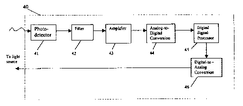
FIG. 4 is a block diagram depicting the flow of information through a
preferred
embodiment of the apparatus of the present invention.
DETAILED DESCRIPTION OF EMBODIMENTS OF THE INVENTION
The present invention comprises an apparatus for measuring an oxygen
concentration
gradient in an aqueous environment and methods of calculating the resulting
measurements.
The present invention uses the phenomenon of oxygen dependent quenching of
phosphorescence, combined with non-toxic, soluble phosphors, and provides an
efficient,
reliable and economical method and apparatus to quickly and quantitatively
determine
oxygen concentrations.
The invention is embodied by an apparatus for measuring the linear oxygen
concentration in a sample comprising the following elements: a) a means for
illuminating the
sample, wherein the sample comprises a phosphorescent compound, at an
intensity and
frequency sufficient to cause the phosphorescent compound to emit a measurable
phosphorescence; b) a means for measuring the emitted phosphorescence; and c)
a means for
calculating the phosphorescence lifetime and oxygen concentration gradient in
the sample.
In a preferred embodiment, the apparatus 40 comprises a phosphorometer
photodetector or device 41 for measuring emitted phosphorescence, containing a
core digital
5
Printed from mimosa 02/07/04 11:25:20 Page: 6
CA 02387492 2002-04-09
WO 01/27585 PCT/US00/41171
signal processor (DSP) 45 with sufficient memory (RAM and ROM) to carry out
the
indicated calculations and to control both the output of the excitation light
source and
collection of the phosphorescence data. In addition, the device contains Delta-
Sigma signal
processors (DSP) (both A/D 44 and D/A 46) for converting calculated data
tables to current
for the excitation light (D/A), and for digitizing the photodetector output
(A/D) for digital
analysis. The DSP, A/D and D/A are preferably 16 bit or greater, and the
memory is
preferably able to operate in 32 bit words or greater.
A preferred instrument for the practice of the present invention is a
phosphorometer,
comprising a core digital signal processor which can be constructed from, for
example,
Analog Devices ADSP-2181 and AL 1847 Stereo Codex with stereo high precision
48kHz,
16 bit, 20 Delta-Sigma ADCs with 64x oversampling. The instrument (as shown in
FIG. 4)
further comprises a filter 42, such as an avalanche photodiode or
photomultiplier for filtering
and detecting emitted phosphorescent light from the sample following exposure
to the
excitation light signal. Moreover, as shown in FIG. 4, the instrument further
comprises an
amplifier 43 for amplifying the output of the photodiode or photomultiplier,
and a second
Delta-Sigma signal processor (A/D analog to digital) responsive to the
amplified output from
the photodiode or photomultiplier, for digitizing the amplified photodetector
output (the
emitted phosphorescence), and for compiling collected data into a separate
memory set, m
(the tabulated calculated data), in the DSP, wherein data is summed to recover
distribution of
the phosphorescent lifetimes, from which oxygen concentration gradient is
calculated from at
least one equation.
A sine wave signal of the desired frequency can be generated by the DSP using
a 16
bit DAC and smoothing circuits of the Stereo Codex. The resulting signal will
control the
current in the LED or laser diode driving circuit. The LED driver circuit is
designed to
provide a greater than 90% modulation of tight output. This is accomplished by
adding a DC
signal to the sinusoidal signal, such that the minimum current is just above
the threshold for
light emission. Above this threshold, the light output is a nearly linear
function of the current
through the LED.
In practice, the apparatus of the present invention applies the following
principles.
Non-toxic phosphorescent compounds are dissolved in the sample or introduced
into the
sample being tested. Then, the sample is illuminated with pulsed or modulated
light to raise
the phosphorescent molecules to an excited state, and the resulting
phosphorescent light. The
6
Printed from Mimosa 02/07/04 11:25:21 Page: 7
CA 02387492 2008-08-27
decay constant is calculated from the resultant measurements; thereby
permitting
determination of the oxygen concentration gradient in the sample.
Phosphorescent Compounds or Phosphors
Measurements in the invention are based upon the quenching of the
phosphorescence of a phosphorescent compound having a known quenching constant
and
known lifespan at zero oxygen for a given temperature. Repeated measurements
can be
used as a quantitative analysis of the time course of alterations in oxygen
content in
response to changed conditions. If the quenching constant and lifespan are
unknown for
a particular compound or phosphor, values can be determined by calibrating the
quenching constant and lifetime at zero oxygen.
"Phosphors" or "phosphorescent compounds" of the present invention include any
02-sensitive compound which is soluble in the substrate being tested, and
which upon
excitation by a selected light source will produce a measurable phosphorescent
light. The
phosphorescent lifetime of the phosphors suitable for the present invention is
diminished
or reduced ("quenched") by 02. The preferred selected phosphors are
hydrophilic or
water soluble, and generally biocompatible.
Although not intended to be limiting, suitable phosphorescent compounds
include
those described in U.S. Patent No. 5,830,138 and U.S. Patent No. 6,362,175,
and as
published in Vinogradov et al., J. Chem. Soc., Perkin Trans. 2:103-111 (1995).
Preferred
porphyrins of the present invention include those hydrophilic compounds having
the
following formula:
Ri R, R2
R2 R3
t N
R, M R1
N ht
R,
R= R, R3
wherein R, is a hydrogen atom or a substituted or unsubstituted aryl; R2 and
R3 are
independently hydrogen or are linked together to form substituted or
unsubstituted aryl;
and
7
CA 02387492 2002-04-09
WO 01/27585 PCT/US00/41171
M is a metal. In certain preferred embodiments, M is a metal selected from the
group
consisting of Zn, Al, Sn, Y, La, Lu, Pd, Pt and salts and derivatives thereof.
Examples of
such porphyrins, while not intended to be limiting, include, e.g.,
tetrabenzoporphyrin,
tetranaphthoporphyrin, tetraanthraporphyrin, and derivatives thereof. More
specifically,
examples of applicable porphyrins, include, e.g., meso-tetraphenylated
derivatives;
tetraphenyltetrabenzoporphyrins; tetraphenyltetranaphthoporphyrins; meso-tetra-
(4-
carboxylphenyl)porphyrins; meso-tetraphenyltetrabenzoporphyrins; meso-10
tetraphenyltetranaphthoporphyrins; and tetrabenzoporphyrins.
More preferred for use in the present invention are known dendritic
derivatives of the
aforementioned porphyrin phosphors, which are highly efficient and highly
soluble
phosphorescent compounds surrounded by an inert globular structure. An example
of such a
compound is a derivatized metallotetrabenzoporphyrin compound, such as Pd-
tetrabenzo-
porphyrin or Pd-meso-tetra-(4-carboxyphenyl) porphyrin. As disclosed in the
`138 patent,
substituent groups are known to impart desirable properties, such as
solubility, to the
preferred phosphorescent compounds.
The preferred porphyrin structures are surrounded by a three-dimensional
supramolecular structure known as a dendrimer. It is known that one-, two-,
and three-layer
polyglutamate dendritic cages synthesized divergently around novel derivatized
extended
metalloporphyrin, oxygen-measuring, phosphor compounds provide phosphors which
are
highly water-soluble in a wide pH range and display a narrow distribution of
phosphorescence lifetimes in deoxygenated water solutions.
The phosphor-containing sample is exposed to a modulated light source capable
of
exciting the phosphor to emit phosphorescent light, which permits measurement
and
calibration of both the phosphorescence intensity and delay time between the
excitation light
intensity and the phosphorescence emission (signal). Therefore, accurate
determination of
the frequency dependence of the signal amplitude and phase is used to
calculate the oxygen
pressure histogram of the sample using algorithms. The measured oxygen
pressure histogram
can then be used to accurately calculate the oxygen concentration gradient
throughout the
sample.
Phosphorescence quenching has been thoroughly verified as a method of
measuring
the oxygen dependence of cellular respiration (see, for example, Vanderkooi,
JM, and Wilson
DF, "A New Method for Measuring Oxygen Concentration of Biological Systems, in
Oxygen
8
Printed from Mimosa 02107/04 11:25:23 Page: 9
CA 02387492 2002-04-09
WO 01/27585 PCT/US00/41171
Transport to Tissue VIII9 Longmuir, ed., Plenum (Aug. 1986); Vanderkooi, JM,
et al., J. Biol.
Chem. 262, No. 12:5476-5482 (April 1987); Wilson et al., J. Biol. Chem.,
263:2712-2718
(1988); Robiolio et al., Am. J. Physiol. 256 (6 Pt 1):C1207-1213 (June 1989);
Wilson, DF, et
al., Adv. Exp. Med. Biol. 316:341-346 (1992); and Pawlowski, M, et al., Adv.
Exp. Med. Biol.
316:179-185 (1992). For detailed data on the calibration techniques and oxygen
measurement capabilities of one widely used phosphor, see Lo et al., Analy.
Biochem.
236:153-160 (1996). At constant temperature, phosphorescence lifetime is
independent of
the other parameters and composition of the sample.
It is important in the present invention to use a compound of known quenching
constant and known lifetime at zero oxygen for a given temperature. Thus, once
the
compound and temperature are determined, calibration need only be made on a
single
occasion, after which the value can be used for all subsequent measurements
involving that
compound.
Measurements according to the present invention are rapid and highly
reproducible.
Less than 2 seconds are required for each measurement and current instruments
have a
measurement-to-measurement variability of less than 1 part in 1000. Due to the
absolute
calibration, equally low variability is attained among different samples
having the same
oxygen pressure.
Excitation of the Phosphor(s)
In accordance with the invention, a light source means, preferably a modulated
light
source, is employed for excitation of the soluble phosphor compound in the
sample to a state
of phosphorescence. A beam of excitation light is passed through the sample
from any
direction, i.e., top to bottom, bottom to top or through the sides, so long as
the beam passes
completely through the sample, equally exciting the phosphor at all layers of
the sample. The
emitted phosphorescence is then collected from any point, so long as the
phosphorescence is
evenly distributed to the collection point.
Phosphorescence lifetime measurements use modulated excitation light, i.e.,
undulated sinusoidally, from 20 to 50,000 Hz, preferably from 50 to 35,000 Hz,
most
preferably from 100 to 20,000 Hz. The preferred measurements detect only those
emissions
that are at a longer wavelength and modulated at the same frequency.
The light source means can be provided by any of several different sources,
including
a flash lamp, a pulsed light emitting diode, or a pulsed laser. In the
preferred mode, the light
9
Printed from Mimosa 02/07/04 11:25:24 Page: 10
CA 02387492 2002-04-09
WO 01/27585 PCT/US00/41171
source is a light-emitting diode (LED), such as a laser diode. LEDs provide
monochromatic
light with a relatively broad bandwidth. The light is preferably passed
through an
interference filter to block the long wavelength "tail" in the emission of the
LED, which
might otherwise interfere with the measurements of the present invention.
Solid state light
sources can be readily modulated at the desired frequency and are
monochromatic, i.e., light
emission occurs primarily in either a broad band up to about 60 nm bandwidth
at halfheight
for LEDs or at a narrow band of 1 run or less for laser diodes. As a result,
minimal optical
filtering is required for optimal application of such light to the measurement
of
phosphorescence lifetimes.
Modulation of the light can be achieved either by direct modulation of the
light source
or by passing the light through a modulation device, such as a flasher or a
rotating wheel with
slots through which the light may pass.
Measuring the Emitted Phosphorescence
The measurements of the present invention are readily adapted to very small
sample
sizes. The present optical method is not dependent on sample path length or
light scattering.
Measurements can easily be made in volumes as low as a few picoliters, and in
spots with
diameters of less than 20 microns.
Measurements of phosphorescence lifetime are independent of the concentration
of
the phosphor(s) in the medium, so long as the phosphor(s) is present in the
medium at a
concentration range needed for oxygen measurement. Within the functional
concentration
range, there is no significant "self quenching" due to energy transfer from
triplet state to
ground state phosphor molecules. This is because of the relatively large size
and charge of
the preferred dendrimer constructs. Measurements of phosphorescence lifetimes
are also
independent of absorption by other chromophores, such as hemoglobin, which may
be
present in the medium. Lifetime measurements are independent of changes in
absorption and
light scattering, as long as the changes do not occur during phosphorescence
decay (<1
msec). This makes the method particularly effective in measuring oxygen in
sample
conditions affected by contaminants, such as colored components.
Based upon the principle that the beam of excitation light passed through the
environment will equally excite the phosphors at all levels, and because the
phosphorescence
lifetime increases as the oxygen concentration in its immediate environment
decreases, the
calculated lifetimes are necessarily proportionally longer for points of lower
oxygen
Printed from Mimosa 02/07/04 11:25:26 Page: 11
CA 02387492 2002-04-09
WO 01/27585 PCT/US00/41171
concentration. Phosphorescence may be measured by any available means in
accordance
with the present invention.
Measuring Phosphorescent Lifetime
In general, two conventional methods for measuring phosphorescence lifetime
(or
decay time) are (i) the "pulse method" in the time domain, and (ii) the "phase
method" in the
frequency domain. The present invention is based upon applications of the
phase method.
In a time domain procedure, the phosphor-containing medium (the "sensor
medium")
is illuminated with a short flash of excitation light and the subsequent
phosphorescence decay
is measured by a time domain device or instrument. In a frequency domain
procedure,
excitation of the sensor medium is accomplished with a modulated light source,
and the phase
difference between excitation and emission is measured by a frequency domain
device or
instrument. The measured phase difference can be deconvoluted into the
distribution of
phosphorescence lifetimes in the sample and the fraction of the total phosphor
with each
lifetime. This lifetime and volume fraction distribution can then be converted
into the
fraction of the sample at each oxygen pressure (concentration), thereby
determining the
oxygen gradient under specific test conditions.
Phosphorescence lifetime from the measured decay and/or intensity is
calculated,
followed by calculation of oxygen partial pressure (concentration) or gradient
in the
environment based upon the oxygen relationship at each point with the
phosphorescence
lifetime and appropriate calibration constants, i.e., quenching constant, and
lifetime in the
absence of oxygen. Therefore, the collected phosphorescence decay data, for
example, will
be the summation of the phosphorescence decays for the phosphor(s) throughout
the sample.
In the pulse method, the sample is excited by a short pulse of light and the
resulting
phosphorescence emission in the longer wavelength is an exponentially decaying
function
with a measurable rate of decline. The pulse method is used in most of the
existing
instruments for oxygen measurement.
By comparison, in the phase method, which is the preferred method of the
present
invention, a sample is excited with modulated light, with absorbed light being
re-emitted as
phosphorescence after a certain delay period. As a result, phosphorescent
emission is also
modulated with the same frequency, but delayed in time (phase shifted) with
respect to the
excitation wave. The resulting phase shift, found experimentally, is used to
calculate the
phosphorescence lifetime.
11
Printed from Mimosa 02/07/04 11:25:27 Page: 12
CA 02387492 2002-04-09
WO 01/27585 PCT/US00/41171
The phase method is preferably used in an embodiment of the present invention
because frequency lock amplification can be advantageously used to greatly
increase
sensitivity. Interference from ambient light is greatly decreased by this
method, since only
signals with the same modulation frequency as the excitation light are
amplified, which
largely eliminates interference by other ambient light sources.
The measurement of phosphorescence lifetimes can be fully automated, for
example
by using light guides or video cameras.
The values of the phosphorescence intensities and lifetimes are tabulated for
later
analysis, and the measurements are repeated as often as necessary until the
desired endpoint
is reached. The time at which the data is measured is recorded, from which the
oxygen
concentration can be calculated. Measurements of the phosphorescence lifetimes
are
extremely reproducible from instrument to instrument, due partly to the
absolute calibration
and partly to the nature of lifetime measurements.
Phosphorescence Detection
In practice, the phosphorescence is collected, passed through appropriate
filters within
or interconnected with the apparatus of the present invention. In accordance
with the present
invention, the phosphorometer photodetector (PD) can comprise, for example, a
silicon
photodiode with a built-in preamp, an avalanche photodiode, a photomultiplier,
or other
known PD devices such as would be known to the practitioner. The
phosphorometer
photodetector output is amplified to provide a signal of optimal voltage for
digitizing by the
analog-to-digital converter (ADC). A photodiode with an internal amplifier is
selected for
the optimal light sensitive surface area and lowest noise level. For example,
the Hamamatsu
Corporation HC120 analog photomultiplier tube assembly with an R3823
photomultiplier has
an appropriate surface area (more than 5 mm) and excellent photosensitivity,
in the 500 v to
900 urn wavelength range.
In a preferred embodiment of the present invention, the emitted light is
filtered and
detected with an avalanche photodiode. The output of the detector is amplified
and passed to
a 16 bit (or greater) Delta-Sigma digitizer operating at 48 or 96 kHz. The
signal from the
photodetector can be further amplified with an AC-coupled operational
amplifier. The quality
of the phase detection depends on the reduction of noise level in the
photodiode output signal.
After amplification, the output signal is delivered to the analog multiplexer
and then input
into the ADC for digitizing.
12
Printed from mimosa 02/07/04 11:25:28 Page: 13
CA 02387492 2002-04-09
WO 01/27585 PCT/USOO/41171
Data collection from the digitizer is synchronized with readings of the
tabulated
values into the D/A unit providing the driving current for the light source.
Data collection is
always begun at the same point in the table of values controlling the LED
light output.
The digitized phosphorescence data is transferred to a specific file in
memory,
preferably at least a 1024 x 32 bit block of memory. Further data sets (a
total of m data sets)
are added to the same memory area, always beginning at the same point. Because
the
collected data are "locked" to the table of values being used to control the
excitation light,
only signals of exactly the same frequencies as those used to generate the
excitation signal
are summed positively. All other signals (and noise) are summed destructively,
and their
amplitudes decrease as the number of scans (m) increases. Noise amplitude, on
the other
hand, increases only as the square root of the number of scans summed (m/),
thus providing
increase in signal-to-noise ratio.
In a preferred, exemplified configuration, 20 data sets would be summed.
Assuming
that each data set is approximately 20 msec long (1024 points at 48 kHz),
summing the 20
sets would require less than 0.5 seconds.
Calculating Oxygen Distribution in terms of Phosphorescent Lifetime
Excitation Light
The LED is modulated to provide light that is a sum of many sinusoidal waves
of
equal amplitude as follows:
N
Ex(t) = B + I A = sin(27fkt) (Eq. 1)
K
The frequencies are selected such that the cycle times for the lower
frequencies are
multiples of the highest frequency. For example, such a set could be selected
which contains
200 frequencies, spaced between 100 and 20,000 Hz, in which case, fk = fl - k
when f, = 100
Hz; k = 1. "N; and N = 200.
The resulting waveform (Eq. 1) presents "nodes" or points at which all of the
component waveforms pass through zero. The time between nodes is set by the
lowest
frequency used. These frequencies are digitally summed, and a DC offset (B,
Eq. 1) is added
to provide a table of values in which all values are positive. The current for
driving the LEDs
is obtained, for example, by sequentially reading the values in the data table
into a Digital to
Analog converter (preferably, 16 bits and 48 kHz) and by amplifying the signal
to provide the
driving current for the light source (LEDs).
13
Printed from Mimosa 02/07/04 11:25:29 Page: 14
CA 02387492 2002-04-09
WO 01/27585 PCT/USO0/41171
Run Time Determination of Magnitude and Phase Angles for Frequencies in Array
Oxygen concentration within a sample increases or decreases linearly depending
upon
conditions. Thus, a constant gradient is formed, which is informative of the
oxygen
concentration within the sample. Consequently, the oxygen concentration
gradient, in
combination with the diffusion constant for oxygen, can be used to accurately
calculate the
rate of oxygen consumption per unit area of the sample. This absolute
calibration, combined
with the lack of interference due to the negligible alterations in sample
position, absorption,
fluorescence, and light scattering, makes the present invention ideal for
automated
measurements.
To calculate and understand the phosphorescence lifetime distribution, and
thus the
oxygen distribution within the sample, the first step is to extract the
dependence of the
phosphorescence amplitude (a) and the phase angle (0) on the modulation
frequency.
Since all modulation frequencies are mixed in the excitation light, the
emitted signal
contains a spectrum of all the resulting phosphorescent lifetimes within the
medium at a
given point in time. Thus, following delivery of the excitation light (Eq. 1),
the
phosphorescence response is calculated as follows:
N
Em(t) = b+Eak sin(2nfkt -qk)
k (Eq. 2)
where ak represents the phosphorescence amplitude and ok represents the phase
angle
for each individual frequency used in the excitation array. Therefore, by
rewriting Eq. 2,
using trivial trigonometry, the emitted signal is calculated as follows:
Em(t) = b + Z [ak sin(291fkt) cos(gk) - ak sin(gle) cos(2llfkt)]
A or
Em(t) = j [P0(fk) sin(2nfkt) - Pl(fk) cos(2nfkt)]+ P2
k (Eq. 3)
where PO(fk) = ak cos (0k), P1(fk) = ak sin(¾k) and P2 = b.
In the present invention, P0(1) and P1(1) represent functions of the
excitation
frequency f (or frequenciesfk if a frequency set was used). Using x2-fitting
("least squares")
of the phosphorescence signal, with the probe function in the form of Eq. 3,
the dependencies
of PO and P1 on the modulation frequency are recovered. Alternatively, Fourier
techniques
can be used to obtain the dependencies. However, the disclosed calculations
based upon
14
Printed from Mimosa 02/07/04 11:25:30 Page: 15
CA 02387492 2002-04-09
WO 01/27585 PCT/US00/41171
linear algebra are, in this case, by far, more accurate, robust and fast
because P0, PI and P2
participate in the probe function (Eq.3) as simple linear parameters.
Recovery of Oxygen Distribution in the Sample:
Once the vectors (or arrays) P0(fk) and P1(fk) are obtained, they are analyzed
to
determine the phosphorescence lifetime distribution for the selected sample.
The distribution
or lifetime spectrum is directly converted into the distribution of oxygen
concentrations using
Stem Volmer equation.
The phosphorescence emitted at a selected time or over a time course from a
sample,
comprising a heterogeneous array of lifetimes, following excitation of the
sample with a flash
of light, is described as an integral in accordance with Eq. 4, known as the
Laplace transform.
I(t) = jg(zexp~ - t Idz
0 l zJ (Eq.4)
Function g (T) describes lifetime distribution or spectrum, while exp(t/i)
presents
what is commonly referred to as a "transform kernel." A "transform kernel" is
a set of
functions over which the linear integral transform is defined.
The kernel of the Laplace transform is the set of real exponentials. This
kernel is
incomplete, and so there are examples of the objects (lifetime distributions)
which cannot be
recovered from the Laplace images. Various numerical methods are used to
invert
"incomplete" integral transforms. The most probable solution for Laplace
transform
inversion can be obtained, for example, using the Maximum Entropy Method.
In a frequency domain the dependencies of the parameters PO and PI on the
modulation frequency are provided by the similar integrals (Eq. 5), which are
the Fourier
images (sine and cosine transforms respectively) of the Laplace integral (Eq.
4):
P0(j) = !g(r) . B(_f, z)dz O(f, z) = z
0 1+COY
W
Pi (f) = jg(z) . y4(f, z)dr 2
o ' z) 1 + w2 zZ
(Eq. 5)
co = 27[f
Since the only difference between the integrals Eq. 4 and Eq. 5 are the
transform
kernels, while the lifetime spectrum remains unchanged, the existing
algorithms for the
Laplace transform inversion can be applied to the recovery of g(T) from the
data presented by
Printed from Mimosa 02/07/0411:25:31 Page: 16
CA 02387492 2008-08-27
P0(t) and Pl()g (Eq. 5). In such algorithms, the shape of continuous g(t) is
approximated
by a finite dimension histogram. The histogram represents an array of numbers,
p = {põ},
corresponding to the fixed lifetimes {tõ} (a "lifetime grid"), spanned in the
range zero to
(tm). Maximal lifetime (tmax) corresponds to the phosphorescence lifetime in
the
absolute absence of oxygen, and thus it is the longest possible lifetime
presented in the
signal. The goal of the numerical methods is finding of the histogram p which
maximally
resembles the shape of g(t).
Quenching of phosphorescence by oxygen is determined by the frequency of
collision between the excited triplet state molecules and oxygen. This means
the
measured phosphorescence lifetime may be converted to oxygen pressure
according to
the Stern-Volmer relationship, which is stated as follows:
t 1t=1+kq=t =P02
where tp and t are the phosphorescence lifetimes in the absence of oxygen, P02
is the
oxygen pressure for a lifetime oft, and kq is the quenching constant. The
constant kq is
related to the frequency of collisions between the excited triplet state
molecules and
molecular oxygen and the probability of energy transfer occurring when these
molecules
collide. Use of the Stem-Volrner relationship is also set forth in US Pat. No.
5,501,225.
Mathematical Relationship between Phase Shift and Phosphorescence Lifetime
In the phase approach, the mathematical relationship between phase shift and
phosphorescence lifetime can be described as follows:
tan o=2atf=t (Eq.7)
where o = phase difference (phase shift) between excitation and emission sine
waves at
the modulation frequency, f, and t = lifetime of phosphorescent decay.
It can be shown that for a given signal-to-noise ratio, the lowest error in
the
estimation of the phosphorescence lifetime is obtained when the phase shift is
about 26 .
It follows from the Stem-Volmer relationship and the diffusion equation that
to
maintain the phase shift of about 26 for all oxygen concentrations in the
range, it is
necessary to be able to vary the modulation frequencies from 20 Hz to 20,000
Hz.
However, it is preferred that modulation frequencies be controlled from 100 Hz
to 20,000
Hz, and instrumentation be employed which can measure phosphorescence lifetime
of a
given fixed
16
CA 02387492 2002-04-09
WO 01/27585 PCT/USOO/41171
frequency and/or at a first estimate optimal frequency for a given value of
the phase shift
(26 ), and to then proceed with actual lifetime measurements. To ensure oxygen
measurements are accurate to air saturation and above (lifetimes as short as <
15 .tsec), the
phosphorescence signal is preferably sampled (digitized) at 48 kHz or greater.
The digital signals will be processed to extract the signal strength
(magnitude) and
phase relative to the excitation light. Calculations of the phosphorescent
lifetime and oxygen
pressure will follow the above-described procedures.
According to our preferred algorithm, a first approximation po is found by
applying a
fast quadratic programming algorithm, based on 0-order Tikhonov's
regularization. The
solution is attained by maximizing a quadratic functional H(p), constructed in
the following
form:
H(p) x2(p) - (p, p) (Eq. 8)
where x2(p) = -(grado, p) + 1/2(p, Qp) is a standard least squares function
and (p, p) is a
Tikhonov's 0-order smoothness regularizer. Parentheses in the expression (p,
p), and in
similar instances, denote the scalar product of the enclosed vectors, which
are shown in bold.
The vector grado is an anti-gradient of x2(p) calculated at the origin, and Q
is a Hessian
matrix (matrix of the second partial derivatives of x2(p)). For a small value
of in the
regularizer, chosen depending on the value of noise in the data, the
optimization of H(p) can
be effectively performed using a robust quadratic algorithm proposed by R.
Shrager,
Numerical Mathematics 15:41 (1972). This algorithm converges in the finite
amount of steps
and assures non-negativity of the solution po.
After the initial solution is found, the following improvement in the shape of
p is
achieved recursively by minimizing another functional:
G(p) = x2(p) - NE(p) (Eq. 9)
using the same algorithm and solution vector pi obtained at the previous step.
In subsequent Eq. 11, functional E(p) = -(p, log(p)) refers to the Shannon-
Janes
entropy. The minimization of G(p) is equal to the maximization of S(p):
S(p) = -G(p)/ = E(p) - x2(p)/g (Eq. 10)
and, after replacing 1/ = X, since is a simple constant, Eq. 11 transforms
into:
S(p) = E(p) - X 'x2(p) (Eq. 11)
17
Printed from Mimosa 02/07/04 11:25:34 Page: 18
CA 02387492 2008-08-27
The value of the regularization constant is dependent on the signal to noise
in the
data., but is constant for computational analysis of any one data set.
The maximization of the functional S(p) is known as Maximum Entropy Method
(MEM), which according to the information theory allows the recovery of the
"best"
uncorrelated histogram p from the noisy data.
For 02 a, = 152 Torr (which is equal to the oxygen pressure in the atmosphere
at
sea level (20% of 760 Torr)), when 02m' = 30 Torr, and x is the selected
distance within
the sample (expressed in % of the total distance L), the oxygen concentration
0(x) will
increase as shown in Fig. 1.
The phosphorescence lifetime, being the reciprocal of oxygen concentration,
will
hyperbolically decrease with increase of the distance x as shown in Fig. 3,
which is a
graph of phosphorescence lifetime versus distance within the sample. Lifetime
is given
in microseconds, assuming io = 350 sec and Kq = 350 Torf 1sec 1, as
characteristic for
the phosphor.
However, the relative intensity P(i) of the phosphorescence lifetime (e.g.,
lifetime
spectrum) is proportional to the lifetime itself, and thus P(T) - the lifetime
spectrum - will
have a simple linear profile (Fig. 3), with the slope directly related to the
oxygen gradient
in the studied sample. Knowing that the distribution must have linear shape
will greatly
improve the accuracy and speed of the MEM recovery, as any a priory
information. The
information about the distribution shape can be directly incorporated into the
recovery
algorithm, thus permitting rapid and efficient calculation of the oxygen
concentration
gradients in the studied samples and providing a reliable, quantifiable and
objective
determination of oxygen concentrations or the effect on oxygen concentrations
in a
sample as a response to changed circumstances.
While the foregoing specification has been described with regard to certain
preferred embodiments, and many details have been set forth for the purpose of
illustration, it will be apparent to those skilled in the art, that without
departing from the
spirit and scope of the invention, the invention may be subject to various
modifications
and additional embodiments, and that certain of the details described herein
can be varied
considerably without departing
18
CA 02387492 2002-04-09
WO 01/27585 PCT/USOO/41171
from the basic principles of the invention. Such modifications and additional
embodiments
are also intended to fall within the scope and spirit of the invention
appended claims.
19
Printed from Mimosa 02/07/04 11:25:36 Page: 20