Note: Descriptions are shown in the official language in which they were submitted.
CA 02387725 2002-03-25
WO 01/28687 PCT/US00/28367
MULTIPLE TOOL ATTACHMENT SYSTEM
BACKGROUND OF THE INVENTION
1. Field of the Invention
The present invention relates to a tool attachment
system for construction or demolition equipment which is
adapted to be attached to a backhoe for attaching multiple
tools, such as a heavy-duty metal cutting shear, a plate
shear, a concrete crusher, a grapple or the like. More
particularly, the present invention relates to a multiple
tool attachment system for attaching tools having plural
movable jaws.
2. Background Information
The present application refers to demolition
equipment, however, the equipment is also referred to as
construction equipment, scrap handling equipment and the
like. The description of demolition equipment or
construction equipment is not intended to be restrictive of
the equipment being referenced. Demolition equipment, such
as heavy-duty metal cutting shears, grapples and concrete
crushers, have been mounted on backhoes powered by hydraulic
cylinders for a variety of jobs in the demolition field.
This equipment provides for the efficient cutting and
handling of scrap. For example, in the dismantling of an
industrial building, metal scrap in the form of various
diameter pipes, structural I-beams, channels, angles, sheet
metal plates and the like, must be efficiently severed and
handled by heavy-duty metal shears. Such shears can also be
utilized for reducing automobiles, truck frames, railroad
cars and the like. The shears must be able to move and cut
the metal scrap pieces regardless of the size or shape of the
individual scrap pieces and without any significant damage to
the shears. In the demolition of an industrial building,
concrete crushing devices, such as a concrete pulverizer or
concrete crackers, are also used to reduce the structure to
manageable components which can be easily handled and removed
from the site. Wood shears and plate shears also represent
specialized cutting devices useful in particular demolition
CA 02387725 2002-03-25
WO 01/28687 PCT/US00/28367
or debris removal situations depending on the type of scrap.
Also, a grapple is often utilized where handling of debris or
work pieces is a primary function of the equipment.
Historically, all of these pieces of equipment represent
distinct tools having significant independent capital cost.
Consequently, the demolition industry has tended to develop
one type of tool that can have the greatest possible utility
and application.
With regard to metal shears, one type of known
shear is a shear having a fixed blade and a movable blade
pivoted thereto. The movable blade is pivoted by hydraulic
cylinder to provide a shearing action between the blades for
severing the work pieces. Examples of this type of shear can
be found in my prior U.S. Patent Nos. 4,403,431; 4,670,983;
4,897,921; 5,926,958; and 5,940,971 which are incorporated
herein by reference.
The prior art has also developed a variety of
demolition tools utilizing a plurality of movable jaws. U.S.
Reissue Patent No. 35,432 and U.S. Patent No. 5,060,378 both
disclose heavy-duty metal cutting shears having a body and a
pair of movable jaws mounted to the frame for pivoting about
a common point. Each jaw includes a plurality of cutting
inserts in shearing relation with the inserts on the other
jaw, with one jaw forming a slot for maintaining the inserts
in shearing relation to each other throughout the cutting
movement. Each jaw is operated by an independent hydraulic
cylinder. The jaw configuration provides a hook-shaped
structure with one of the jaws having a cutting or piercing
tip at the end thereof. However, these patents do not
optimize the jaw structure for the purpose of cutting.
Additionally, the independent cylinders increase the cost and,
prevent a compact shear design.
U.S. Patent No. 5,359,775 discloses a metal cutting
shear with a pair of movable jaws pivotally mounted to a
frame with a pair of jaws operated off of a common piston
extending between the jaws.
-2-
CA 02387725 2002-03-25
U.S. Patent Nos. 4,838,493; 4,890,798; 5,044,569;
5,636,802; and 5,738,289 all disclose a variety of concrete
crushers having a plurality of movable jaws operated through
hydraulic cylinders. U.S. Patent Nos. 4,903,408; 5,044,568;
5.,199,658; 5,243,761; and 5,626,301 also disclose a variety
of demolition equipment having a plurality of movable jaws.
The prior art does not provide a system for easily
changing tools or a system which allows complete separate
tools to efficiently share a common structure. Further, the
prior art fails to optimize the jaw structure utilized in the
individual tools, such as metal cutting shears, to maximize
power and efficiency. Additionally, the prior art provides
a complex arrangement for rotations of the tool and jaws
without sufficient protection for any hydraulic cylinder
powering the working jaws.
SUMMARY OF THE INVENTION
The aspect of the present invention is to overcome
the aforementioned drawbacks of the prior art. It is a
further aspects of the present invention to provide a multiple
tool attachment system which is easily converted between a
plurality of distinct tools. A further aspect of the present
invention is to provide a demolition tool having a plurality
of movable jaws which optimizes the jaw structure. A further
aspect of the present invention is provide a demolition tool
which optimizes the ratio between the jaw and the jaw power
structure to provide optimum power performance throughout the
blade movement cycle. A further aspect of the present
invention is to provide a demolition tool system that
simplifies the construction of the tool system, including
rotating tools. A further aspect of the present invention is
to provide a method for designing a demolition tool and tool
system.
The aspects of the present invention are achieved
by a multiple tool attachment system according to the present
invention. The attachment system is adapted to be attached
to demolition equipment, also referred to as construction
-3-
CA 02387725 2002-03-25
WO 01/28687 PCT/US00/28367
equipment, scrap handling equipment and the like. The system
includes a universal body attachable the demolition
equipment, a hydraulic cylinder attached to the universal
body, a pair of linkages adapted to be coupled with the
hydraulic cylinder, and a plurality of demolition tool units
each selectively, removably attachable to the body and the
hydraulic cylinder.
Each tool unit includes a pair of pivotable blades
or jaws adapted to be pivotally connected to the body and to
the pair of linkages. In one embodiment, the tool unit
includes a pair of movable blades pivoted together with a
common pivot pin connecting the blades together, and a bridge
housing coupled to the pivot pin providing a quick release
system for attaching the tool set to the body.
In one embodiment of the invention, the universal
body includes a guide slot extending longitudinally along the
body. A slide member is received within the guide slot, with
each linkage attached to the slide member and the piston
cylinder arrangement attached to the body and coupled to the
slide member for moving the slide member and the blades. The
linkages may be attached to the slide member at a common
point. Additionally, the linkages may have a common sleeve
adapted to hold the linkages together when decoupled from the
slide member. The universal body may be provided with
pivotable sides and/or with side access panels to assist in
repair, maintenance and tool changing.
The demolition equipment is provided with quick
change features and is designed to optimize the cutting
characteristics throughout the movement cycle. Specifically,
the lengths of the linkages and the lengths of the relevant
lever arms for each blade of a tool set may be set to be
substantially equal or varied. In general, these jaw and link
dimensions may be selected for a desired positioning of the
power curve of the jaw to optimize the performance throughout
the intended operating conditions. The jaw and link
dimensions may be selected to shape or regulate the power
-4-
CA 02387725 2002-03-25
WO 01/28687 PCT/US00/28367
curve in a desired manner. For example, the relative
dimensions of the jaw sets may be selected to provide an
increasing power curve throughout the blade closing motion
or, alternatively, the relative dimensions of the jaw sets
may be selected to have the power curve peak slightly before
the end of the blade closing motion. In one shear of the
present invention, the jaw depth and maximum jaw opening are
also the same as the lever arm and linkage lengths.
Additionally, the jaw design of the shear of the present
invention is designed to perform the" majority of the heavy
cutting at the throat of the plural moving jaws. The
concepts of the present invention can be incorporated into a
guided single moving blade demolition tool.
These and other advantages of the present invention
will be clarified in the description of the preferred
embodiments wherein like reference numerals represent like
elements throughout.
BRIEF DESCRIPTION OF THE DRAWINGS
Fig. 1 is a side view illustrating a heavy-duty
shear according to the present invention incorporated into a
universal body for a construction tool system according to
the present invention;
Fig. 2 is a side view of a shear similar to the
shear of Fig. 1 without a rotator in the body;
Fig. 3 is a side view of the shear in Fig. 1 with
an outer side panel of the body removed;
Fig. 4 is a sectional view taken along line A-A of
Fig. 3;
Fig. 5 is a plan view of the shear in Fig.l;
Fig. 6 is an enlarged plan view, partially in
section, of a slide member of the universal body according to
the present invention;
Fig. 7 is a side view of the slide member
illustrated in Fig. 6;
-5-
CA 02387725 2002-03-25
WO 01/28687 PCT/US00/28367
Fig. 8 is a plan view, partially in section, of a
main shaft assembly of a tool unit mounted on the universal
body of the construction tool system shown in Fig. 1;
Figs. 9-lla sequentially illustrate the disassembly
of a tool unit mounted on the universal body of the
construction tool system shown in Fig. 1;
Fig. lib is a front view of a modified bridge of
the quick change system of the present invention;
Fig. llc is an exploded view of the quick change
system used with the modified bridge of Fig. llb;
Fig. lid is a side view of a keeper pin used in the
quick change system of Figs. llb-c;
Fig. 12 is aside view of a plate shear according
to the present invention incorporated into the universal body
of Fig 1;
Fig. 13 is a front view of the plate shear
illustrated in Fig. 12;
Fig. 14 is a side view of a concrete cracker
according to the present invention incorporated into the
universal body of Fig. 1;
Fig. 15 is a front view of the concrete cracker
illustrated in Fig. 14;
Fig. 16 is a side view of a concrete pulverizer
according to the present invention incorporated into the
universal body of Fig.1;
Fig. 17 is a front view of the concrete pulverizer
illustrated in Fig. 16;
Fig. 18 is a side view of a wood shear according to
the present invention incorporated into the universal body of
Fig.. 1;
Fig. 19 is a front view of the wood shear
illustrated in Fig. 18;
Fig. 20 is a side view of a grapple according to
the present invention incorporated into the universal body of
Fig. 1;
-6-
CA 02387725 2002-03-25
WO 01/28687 PCT/US00/28367
Fig. 21 is a front view of the grapple illustrated
in Fig. 20;
Fig. 22 is a side view of an iron and rail cracker
according to the present invention incorporated into the
universal body of Fig. 1;
Fig. 23 is a front view of the iron and rail
cracker illustrated in Fig. 22;
Fig. 24 is a sectional view of the universal body
illustrated in Fig. 1 taken along line A-A of Fig. 5;
Fig. 25 is a sectional view of a hydraulic cylinder
for the universal body of the present invention;
Fig. 26 is a side view. schematically illustrating
a jaw and a linkage arrangement of the shear of Fig. 1;
Fig. 27a is a graph of the power curve and relative
jaw position for a shear having the linkage arrangement
according to Fig. 26;
Fig. 27b is a graph of the power curve of a shear
designed according to the present invention to have the power
curve peak near the end of the jaw motion;
Fig. 28 is a side view similar to Fig. 1
illustrating a heavy-duty shear according to another
embodiment of the present invention;
Fig. 29 is a top view of the shear illustrated in
Fig. 28;
Fig. 30 is a sectional view of the shear
illustrated in Fig. 28;
Figs. 31-34 sequentially illustrate the disassembly
of a tool unit mounted on a universal body illustrated in
Fig. 28;
Fig. 35 is a side. view of the shear according to
Fig. 28 incorporated into a modified universal body;
Fig. 36 is a plan view of a modified universal body
according to the present invention;
Fig. 37 is a plan view of another modified
universal body according to the present invention;
-7-
CA 02387725 2002-03-25
WO 01/28687 PCT/US00/28367
Fig. 38 is a side view of the universal body
illustrated in Fig. 37;
Fig. 39 is a side view of the shear according to
Fig. 28 incorporated into a modified universal body;
Fig. 40 is a plan view of the universal body
illustrated in Fig. 39;
Fig. 41 is a schematic side view of a shear
according to the present invention incorporated into a
further modified universal body;
Fig. 42 is a schematic side view of a jaw portion
of a shear according to the present invention;
Fig. 43 is a side view, partially in section, of a
shear according to the present invention incorporated into a
further modified universal body;
Fig. 44 is a side view of a shear according to the
present invention;
Fig. 45 is a side view, with a front side removed
for clarity, of the shear illustrated in Fig. 44;
Fig. 46 is a sectional view taken along line A-A of
Fig. 45;
Fig. 47 is a schematic side view of a shear
according to the present invention; and
Fig. 48 is a schematic side view of the shear
illustrated in Fig. 47 in the closed position;
Fig. 49 is a side view, partially in section, of a
shear according to the present invention incorporated into a
further modified universal body;
Fig. 50 is a rear view of a rotary coupling of the
shear in Fig. 49;
Fig. 51 is an enlarged view of a connector pin
assembly for the rotary coupling in Fig. 50;
Fig. 52 is a side view of an adapter of the shear
in Fig. 49;
Fig. 53 is a front view of the adapter of Fig. 52;
-8-
CA 02387725 2002-03-25
WO 01/28687 PCT/US00/28367
Fig. 54 is a side view, partially in section, of a
shear similar to the shear of Fig. 49 without a rotary
coupling in the body; and
Fig. 55 is a side view, partially in section, of a
shear similar to the shear of Fig. 49 and formed as a stick
mounted type shear.
DESCRIPTION OF THE PREFERRED EMBODIMENTS
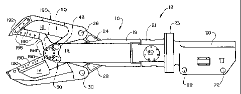
Fig. 1 illustrates a multiple tool attachment
according to the present invention adapted to be attached to
demolition equipment, such as a backhoe (not shown). The
multiple tool attachment is adapted to connect one of a
series of tools or tool units to the demolition equipment.
Fig. 1 illustrates a shear 10 coupled to the
multiple tool attachment. The shear 10 includes a first
blade 12 and second blade 14 pivotally connected at a hub or
main pin 16 to a universal body 18. The universal body 18 is
referred to as the universal body 18 because it remains
common to a series of tools or tool units in the attachment
system according to the present invention. The universal
body 18 is comprised of sides 19, bearing housing 20 and yoke
21. The main pin 16 provides a common pivot for both the
first blade 12 and second blade 14.
The bearing housing 20 includes spaced mounting
apertures 22 for attaching the universal body 18 to the
demolition equipment in a conventional fashion through an
adaptor (not shown). The adaptor will pivotally connect the
universal body 18 to the demolition equipment and to a
controlling piston for pivoting of the universal body 18.
The adapter is intended to conform to the specific demolition
equipment such that the shape of the adapter will differ
depending on the specific demolition equipment utilized.
A rotary coupling 23 is between the bearing housing
20 and the yoke 21. The rotary coupling 23 allows for a
rotation of the remaining portions of the universal body 18
relative to the bearing housing 20 and the associated
demolition equipment. Essentially, the rotary coupling 23
-9-
CA 02387725 2002-03-25
WO 01/28687 PCT/US00/28367
allows for 360 degree rotation for angular orientation of the
universal body 18 and associated tool such as shear 10. A
motor 25, as shown in Fig. 5, is attached to the bearing
housing 20 and geared to the rotary coupling 23 for
rotationally positioning the universal body 18.
Fig. 2 illustrates a shear 10' similar to shear 10
illustrated in Fig. 1. The shear 10' has a modified
universal body 18' that does not include a rotary coupling
attached to the bearing housing 20. A bearing housing 20'
and a yoke 21' are of a unitary construction. The universal
body 18' is appropriate where no rotation of the tool is
desired.
As best shown in Fig. 3, a first linkage 24 is
pivotally connected at a removable pivot pin 26 to the first
blade 12 and a second linkage 28 is pivotally connected at a
removable pivot pin 30 to the second blade 14. The first
linkage 24 and second linkage 28 are pivotally connected to
a slide member 32 at a common pivot pin 34. The slide member
32 is attached to a piston rod 36, as shown in Fig. 25, which
is movable by a double-acting hydraulic cylinder 38 (shown in
the universal body 18 in Fig. 30). The hydraulic cylinder 38
is pivotally attached to the universal body 18 through
trunnion 40. The details of the hydraulic cylinder 38 are
shown in Figs. 24 and 25 and are described in detail below.
As shown in Figs. 3 and 4, sides 19 of the
universal body 18 include a longitudinally extending slot or
groove 44 which receives and guides the slide member 32 as
shown in Fig. 4. The pivot pin 34 for connecting the first
linkage 24 and second linkage 28 to the slide member 32 is
aligned with the piston rod 36 and hydraulic cylinder 38 as
illustrated in the figures. Having the linkages 24 and 28
attached to the slide member 32 at a common point in-line
with the hydraulic cylinder 38 helps maximize the power and
efficiencies of the tool, such as shear 10, while minimizing
the detrimental forces acting on the hydraulic cylinder 38.
Additionally, the guiding of slide member 32 within a slot 44
-10-
CA 02387725 2002-03-25
WO 01/28687 PCT/US00/28367
resists torsional forces which otherwise disrupt the action
of the tool and the operation of the hydraulic cylinder 38.
The structure of the slide member 32 is shown in detail in
Figs. 4 and 6-7 and will be described in detail below.
A significant feature of the multiple tool
attachment of the present invention is the quick change
design incorporated into the connection between the jaw set
of a specific tool and the universal body 18. This
connection and the process of disassembly is shown in Figs.
9-11a. A bridge housing 48 surrounds the main pin 16 and is
utilized for quickly and easily attaching the main pin 16 and
the associated jaw set to the universal body 18.
Specifically, the sides 19 include receiving members 42 at
the ends thereof which are adapted to be received in grooves
in the bridge housings 48 for attaching the universal body 18
to the bridge housing 48. Keeper pins 50 are received through
apertures 52 in the bridge housing 48 and the receiving
members 42. Keeper screws or bolts 54 can be used to secure
each keeper pin 50 to one bridge housing 48. In this
arrangement, the outer bearing structure surrounding the main
pin 16 will remain affixed even when the tool unit is removed
from the universal body 18. This provides the advantage that
all the bearing or rotating surfaces will be protected from
dirt and grit even when the tool unit is disassembled. A
modification of the quick connecting system is shown in Figs.
11b-d. Figs. llb and lic show a modified bridge housing 48'
which receives keeper pins 50' in apertures 52 in the bridge
housing 48'. The keeper pins 50' are held in place by the
keeper 54' as shown in Fig. llc. Specifically, the shaft of
the keeper 54' is received in a locking groove 55 formed in
the keeper pins 50' as shown in Fig. lld. Figs. llb-d
illustrate that various modifications may be made to the
quick change system within the scope of the present
invention. Each keeper 54' is held in place by a retainer
55', such as a threaded plug or the like.
-11-
CA 02387725 2002-03-25
WO 01/28687 PCT/US00/28367
The quick change design of the present invention
allows the universal body 18 to accommodate a wide variety of
tool units. For example, the shear 10 formed by the first
blade 12 and second blade 14 can be replaced with a plate
shear 100 illustrated in Figs. 12 and 13 having distinct
blades 102 and 104. The plate shear 100 is similar to shear
except that the jaw of blades 102 and 104 is specifically
designed for cutting plate. The plate shear 100 is similar
to the shear 10 in that it is specifically designed for
10 cutting metal products.
Figs. 18 and 19 illustrate a wood shear 110
utilized with the universal body 18 of the present invention.
Wood shear 110 includes blades 112 and 114 specifically
designed for cutting wood products.
Figs. 14 and 15 illustrate a concrete cracker 120
for use with the universal body 18. The concrete cracker 120
includes jaws 122 and 124 designed specifically for cracking
concrete structures. Each jaw 122 and 124 includes concrete
crushing inserts 126 at a distal end thereof cooperating with
the crushing insert 126 on an opposite jaw 122 or 124 as well
as cutting inserts 70 adjacent the main pin 16 which provide
a shearing relationship with the cutting inserts 70 of the
associated jaw 122 or 124.
Figs. 16 and 17 illustrate a concrete pulverizer
130 for use with the universal body 18 of the present
invention. The concrete pulverizer 130 includes jaws 132 and
134 associated with crushing of concrete. The jaws 132 and
134 include crushing inserts 126 cooperating with inserts 126
on an opposite jaw 132 and 134.
Figs. 20 and 21 illustrate a grapple 140 for use
with the universal body 18 of the present invention. The
grapple 140 includes jaws 142 and 144 having hook-shaped
tines 146 extending from each jaw 142 and 144. The tines 146
of each jaw 142 and 144 are designed to extend between spaces
of the tines 146 on the opposed jaw 142 or 144 such that the
-12-
CA 02387725 2002-03-25
WO 01/28687 PCT/US00/28367
tines 146 can overlap in a closed position to completely
encircle the work piece.
Figs. 22 and 23 illustrate an iron and rail cracker
150 for use with the universal body 18 of the present
invention. The iron and rail cracker 150 includes jaws 152
and 154 having interposed inserts 156 thereon. The iron and
rail cracker 150 is designed to crack rail and cast iron
products, such as engine blocks and the like.
The series of tools illustrated in the figures is
merely intended to be representative of the tools which can
be designed for use with the universal body 18. The quick
disconnect feature provided by the bridge housing 48 on each
tool facilitates the rapid tool change of the present
invention. It will be appreciated that the linkages 24 and
.28 must also be disconnected during the change. This is
easily accomplished through removal of the respective pivot
pins 26 and 30. Consequently the linkages 24 and 28 can be
considered part of the universal body 18 since these are
likely to be common to multiple tool sets. It is also
possible to change out the linkages with the tool sets by
either disconnecting the linkages 24 and 28 from the slide
member 32 or disconnecting the slide member 32 from the
hydraulic cylinder 38. This may be desired where a tool set
requires a'change in the linkage lengths. Different tools
may have different respective linkage lengths.
Due to the rotation of the forward portions of the
universal body 18 through the rotary coupling 23, the
rotation must be addressed in the hydraulic cylinder 38 and
the hydraulic lines leading thereto. The hydraulic cylinder
38 is provided as a combined hydraulic cylinder and rotary
joint to accommodate the provision of the rotary coupling 23.
As shown in Figs. 24 and 25, the hydraulic cylinder 38
includes a cylinder housing 160 which is rotatable with the
universal body 18 through the trunnion 40. The cylinder
housing 160 includes a cylinder extension 162 attached
thereto which includes hydraulic lines 164 and 166
-13-
CA 02387725 2002-03-25
WO 01/28687 PCT/US00/28367
appropriately coupled for driving opposite ends of a piston
168 within the cylinder housing 160. The piston rod 36 is
attached to the piston 168. The cylinder extension 162 is
received within a stationary housing 170 which is secured to
the bearing housing 20. The stationary housing 170 includes
hydraulic ports 172 and 174 communicating with respective
hydraulic lines 164 and 166. As illustrated in Fig. 25, the
hydraulic ports 172 and 174 are channels around the interior
of stationary housing 170 which provides constant fluid
communication between the hydraulic ports 172 and 174 and the
associated hydraulic lines 164 and 166 throughout rotation of
the cylinder extension 162 relative to the stationary housing
170. Hydraulic lines 176 and 178 extend from the ends of
hydraulic lines 164 and 166 to the appropriate interior
portions of the cylinder housing 160 as shown in Fig. 25.
This design of the hydraulic cylinder 38 accommodates the
provision of a rotary coupling 23 without the need for a
separate rotary joint. This design also provides a far more
compact arrangement for the universal body 18 than if a
separate rotary joint were utilized.
Fig. 26 illustrates the geometric relationships of
the shear 10 according to the present invention. As
illustrated in Fig. 26, the relevant parameters for the shear
10 include the lengths of each linkage 24 and 28 and lever
arms 180 and 182 of the first blade 12 and second blade 14,
respectively. The lever arms 180 and 182 for each blade 12
and 14 is the distance between the respective pivot pins 26
and 30 and the main pin 16. Further parameters include the
jaw depth defined as the distance between the tip of the jaw
and the innermost usable portion of that jaw and the maximum
shear opening between the respective ends of the first blade
12 and second blade 14 as illustrated in Fig. 26. The shear
10 of the present invention optimizes the operational
characteristics by analyzing and setting these dimensions to
properly position the associated power curve. For example,
in one embodiment, the power curve shown in Fig. 27a is set
-14-
CA 02387725 2002-03-25
WO 01/28687 PCT/US00/28367
to continuously increase throughout the jaw movement by
providing the shear opening, the shear jaw depth, the knife
lever arm and links having substantially the same dimensional
lengths. Maintaining these elements as substantially equal
may help maximize the jaw opening as well as jaw depth and
available shear tonnage. The present invention provides for
the shaping and regulation of the power curve by selecting
the relative dimensions accordingly. For example, Fig. 27b
shows the power curve for one embodiment of the present
invention in which the dimensions are selected so that the
power curve peaks near the end of the cutting motion.
The cutting effort for each blade 12 or 14 as a
function of the linkage geometry utilized in the shear 10 is
calculated according to the following equation:
Cutting Effort=(Lever Arm) x (Cylinder Force/2) x
sin(p)/cos(h); wherein P is the angle between the lever arm
180 and 182 and the associated linkage 24 or 28 and 0 is the
angle between the longitudinal axis of the cylinder 38 and
the respective linkage 24 or 28.
The cutting force produced by the shear 10 at any
location along the shear cutting edge can be calculated by
dividing the cutting effort by the distance measured from the
main pin 16 to the desired location along the blade 12 or 14.
In order to optimize the geometric parameters of the shear 10
according to the present invention, the above parameters were
varied and the resulting cutting torques where studied. The
cutting torque is defined as the torque applied to the
respective blade 12 or 14 about the main pin 16 by the
hydraulic cylinder 38 through the piston rod 36, slide member
32 and associated linkage 24 or 28. This torque can be
converted to a single force along the blade 12 or 14 by
dividing the torque by the distance from the center of the
-15-
CA 02387725 2002-03-25
WO 01/28687 PCT/US00/28367
main pin 16 to the desired location on the blade 12 or 14.
The numerical value of the cutting torque is at its minimum
when the blades 12 and 14 are fully open. The torque
continuously increases in value as the blades 12 or 14 move
to the fully closed position. Fig. 27a illustrates the
favorable cutting force or power curve achieved with one
shear of the present invention. Fig. 27a illustrates the
force generated at the throat and piercing tip for the shear
through the various jaw positions which is shown in the
10 lower portion of the graph. It is of particular importance
to note that the power curve of this shear continually
increases throughout the jaw closing cycle. The jaw position
is graphed as the distance between the piercing tip and the
lower jaw with the negative values reflecting when the
portions of the upper jaw are moving through a slot in the
lower jaw. The relative dimensions of the jaw parameters can
be selected to vary the power curve as desired. For example,
it may be advantageous to have the power curve peak slightly
before the end of the jaw cycle when the maximum cutting
forces are needed such as shown in Fig. 27b. Providing the
linkage lengths slightly greater than the lever arms may be
used to achieve this design.
A review of the effect of changing the relevant
parameters will clarify the advantages of the design of the
shear 10 of the present invention as well as the tool design
method of the present invention. Increasing the length of
the lever arm 180 or 182 of the respective blade 12 or 14
results in the increased values of cutting torque for all
positions of the blade 12 or 14 from fully open to fully
closed. However, the length of the respective lever arm 180
and 182 is, of course, limited by the desired overall
dimensions of the shear 10. Varying the length of the
linkages 24 and 28 has various effects on the cutting torque.
If the linkages 24 and 28 are longer than the respective
lever arms 180 and 182, the cutting torque curve versus the
blade 12 and 14 position will increase in value until
-16-
CA 02387725 2002-03-25
WO 01/28687 PCT/US00/28367
reaching a peak and then decreasing until the blades 12 and
14 are closed. One embodiment of the present invention
utilizes this concept to position the maximum cutting torque
near the end of the jaw moving cycle. If the length of the
linkages 24 and 28 are shorter than the respective lever arms
180 and 182, the torque value will continuously increase from
the open to the closed position. As the length of the
linkage arms 24 and 28 increases, the value of the cutting
torque at the open position increases and the value of the
closed position decreases. Having the linkages 24 and 28
substantially the same length as the lever arms 180 and 182
results in one shear design which considers all of the
factors to be balanced.
The hydraulic cylinder 38 also has an effect on the
power of the associated shear 10. Increasing the diameter of
the hydraulic cylinder 38 results in an increased cutting
torque for all the blade positions (12 and 14) and also
increases the open/closed cycle time for the shear 10. The
size of the hydraulic cylinder 38 is effectively determined
by the size of the shear 10 and the operating conditions
desired.
In addition to the lengths of the linkages 24 and
28 and the length of the respective lever arms 180 and 182,
the value of the angles 8 between the respective linkages 24
and 28 and the longitudinal axis of the hydraulic cylinder
38, and an angle p between the lever arm 180 and 182 and the
longitudinal axis of the hydraulic cylinder 38 will depend on
the initial distance between the pivot pin 34 and the main
pin 16 in the fully open position. To allow for the needed
pin diameters, required bushings and the like, the initial
values of these angles should be at least 20 degrees. Due to
the nature of the force transmission at pivot pin 34 and
slide member 32, the final value of these angles will be less
than 90 degrees and should be approximately 80 degrees.
The initial distance between pivot pin 34 and main
pin 16 is limited by two physical limitations. First, the
-17-
CA 02387725 2002-03-25
WO 01/28687 PCT/US00/28367
distance must be less than the sum of the lengths of the
respective lever arm 180 and 182 and linkage 24 or 28 by
enough to allow the angles 0 and cp discussed above to be at
least about 20 degrees in the open position. Second, this
distance must be large enough so that the pivot pin 34 will
not run into the main pin 16 at the closed position.
Decreasing the length of this initial distance decreases the
cutting torque at all positions.
Another issue to review is the total jaw rotation
angle. Increasing the size of the initial jaw opening
increases the angular rotation necessary to go from the open
position to the closed position. However, increasing this
rotational angle also has an effect on the cutting torque
curve. Increasing the total rotation angle causes an
increase in the cutting torque when the jaws are almost fully
open and a decrease in the cutting torque when in the fully
closed position. Balancing all of the above considerations
in the design of the shear 10 of Fig. 1 results in the shear
opening, jaw depth, lever arm and linkage length being all
substantially the same dimensional length. This ratio works
for shears of all sizes such that the specific value of this
dimensional length will depend upon the size of the shear
desired. This relationship between the linkage length and
the lever arm may also be maintained for the various tools
illustrated in Figs. 12-23. The other relationships may be
altered due to jaw structure changes.
Another important aspect of the present invention
is the jaw structure of shear 10. The cutting edge of the
first blade 12 is formed of a plurality of removable cutting
inserts 190 removably attached to the first blade 12 by bolts
or the like as well-known in the art. These inserts 190 may
be indexible, meaning that the inserts 190 may be removed and
rotated to provide new cutting edges as one cutting edge is
worn. The first blade 12 includes a piercing tip 192 at a
distal end of the first blade 12. The piercing tip 192 is
also a removable cutting insert. However, the piercing tip
-18-
CA 02387725 2002-03-25
WO 01/28687 PCT/US00/28367
192 is intended to primarily make a cut transverse to the cut
supplied by the cutting inserts 190. Specifically, the
primary cut of the piercing tip 192 would be extending into
and out of the illustration in Fig. 1. Additionally, the
cutting inserts 190 along the first blade 12 are positioned
in a hook shape to provide a first cutting portion 194 and a
longer second cutting portion 196 positioned between the
first cutting position 194 and the piercing tip 192. The
shear 10 is designed so that the first cutting portion 194 is
significantly less than, and preferably approximately one-
half of, the length of the second cutting portion 196. The
second blade 14 includes a plurality of cutting inserts 190
which are positioned in shearing relation with the cutting
inserts 190 and piercing tip 192 to provide the shearing
action for the shear 10. The second blade 14 provides a slot
for the first blade 12 to extend through during the shearing
action with the slot helping to maintain the cutting inserts
190 in shearing relation. The jaw design of the first blade
12 and second blade 14 in the shear 10 is constructed to help
move material to be severed to the throat area adjacent the
main pin 16 where the cutting forces are the highest. Having
the piercing tip 192 sever the work piece in a direction
transverse to the cutting of the first cutting portion 194
and second cutting portion 196 will help draw the material
back to the throat. Additionally, the hook shape, i.e., the
angle, between the first cutting portion 194 and the second
cutting portion 196 will also serve to pull the material back
to the throat area. Finally, the provision of the first
cutting portion 194 having a dimension significantly less
than the second cutting portion 196, will further assure that
the material is pulled closer to the throat for cutting.
This is believed to provide a significant improvement over
the jaw designs of existing shears with plural movable blades
and compliments the power curve associated with the shear
design to magnify the effective shearing force. It is also
within the scope of the present invention that different
-19-
CA 02387725 2002-03-25
WO 01/28687 PCT/US00/28367
shapes for the piercing tip 192 may be utilized for different
types of material. Specifically, a piercing tip having a
sharper or shallower angle when viewed from the side may be
more or less appropriate for distinct types of work pieces.
Fig. 5 additionally illustrates that the sides 19
of the universal body 18 are pivoted to the yoke 21 through
side pivots 78. This allows for easy replacement of the
first and second blades 12 and 14 with the associated
linkages 24 and 28, if desired. The pivotable sides 19 of
the universal body 18 can be secured together by bolts or
other fastening members. A rectangular tie bar 79 is
positioned between the pivotable sides 19 through which the
securing bolts extend. The tie bar 79 helps to maintain
structural integrity of the universal body 18.
Figs. 28-30 illustrate a shear 10 similar to shear
10 of Fig. 1, except that the quick change feature is
modified to utilize the pivoting sides 19 of the universal
body 18. Specifically, the bridge housing 48 has been
omitted and the main pin 16 is used to couple the jaw set
directly to the universal body 18. Fig. 29 illustrates bolts
198 which can be used for holding the sides 19 of the
universal body 18 together.
Figs. 31-34 schematically illustrate the process of
disassembling the jaw structure and inserting a new jaw
structure at the main pin 16 for the quick change device
shown in Figs. 28-30. As best shown in these figures, this
design essentially keeps the structure generally symmetrical
about the center line thereby avoiding inappropriate torquing
during use of the shear 10. It will be appreciated that
bearing sleeves 202 may be positioned between appropriate
elements and the main pin 16. Retaining members 204 may be
secured for holding the assembly in place.
As illustrated in Fig. 32, by removing retaining
bolts 206, a retaining cap 208, retaining clips 210 and an
alignment sleeve 212 from attachment with the sides 19 of the
universal body 18, the main pin 16 and associated assembly is
-20-
CA 02387725 2002-03-25
WO 01/28687 PCT/US00/28367
ready for removal. As shown in Fig. 33, once the retaining
system has been disassembled, the sides 19 of the universal
body 18 rotate outwardly to simplify the removal process.
It will be apparent that before the first and
second blades 12 and 14 can be removed, the linkages 24 and
28 must be detached from either the first and second blades
12 and 14 or the slide member 32. In general, the pivot
pins 26 and 30 are removed for disconnecting the linkages 24
and 28 from the respective blades 12 and 14. However, it is
possible for the linkages 24 and 28 to remain with the blades
12 and 14 as a single tool unit. This may be important if
different linkage lengths are desired for the next tool set.
Maintaining the first linkage 24 and the second
linkage 28 with the first and second blades 12 and 14
requires the decoupling of the linkages 24 and 28 from the
slide member 32, or alternatively, decoupling the slide
member 32 from the piston rod 36. In this latter
arrangement, the decoupling of the slide member 32 from the
piston rod 36 can be by bolts, a pin type connection or other
secure fastening which can be easily disassembled. A
continuous sleeve 214, shown in Fig. 6, is positioned around
pivot pin 34 which couples the linkages 24 and 28 to the
slide member 32. The sleeve 214 provides that the linkages
24 and 28 will be held together in a single assembly around
sleeve 214 following the removal of pivot pin 34. This
structure allows the linkages 24 and 28 to be removed, if
needed. The removal of the linkages may be desired so that
the linkage lengths can be changed with the next tool set.
Regardless of how the linkages are decoupled, with the
linkages 24 and 28 decoupled and the sides 19 of the
universal body 18 rotated outward, the entire jaw structure
comprising the blades 12 and 14, and linkages 24 and 28, if
maintained with the blades 12 and 14, can be removed and a
separate tool assembly installed (with new linkages 24 and 28
if these were removed). Following this assembly, the sides
of the universal body 18 will be pivoted back together and
-21-
CA 02387725 2002-03-25
WO 01/28687 PCT/US00/28367
the retaining system attached around a new main pin 16 such
as shown in Fig. 32. Bolts will reattach the sides 19 of the
universal body 18 to complete the reassembly. As shown in
Fig. 34, the new blades 12 and 14 have different retaining
members and bearing sleeves associated with this particular
tool unit. A particular bearing structure will be designed
in accordance with the specific tool unit implemented.
Fig. 35 illustrates a shear 10 which incorporates
a side access plate 222 for permitting access to the slide
member 32 and the associated pivot pin 34. Specifically, the
universal body 18 includes the access plates 222 secured
thereto which can be removed to gain access to the guided
slide member 32 within the universal body 18.
Fig. 36 illustrates a modified universal body 18 in
which the bolts for attaching the pivotable sides 19 of the
universal body 18 are replaced with a retaining connection
224.
Figs. 37 and 38 illustrate a modified universal
body 18 in which the sides 19 of the universal body 18 are
pivoted about side pivots 78 and are secured by independent
retaining connections 224 to the universal body 18.
Figs. 39 and 40 illustrate a further modified
universal body 18 in which the sides 19 of the universal body
18 are completely separable from the remaining portions of
the universal body 18 and secured thereto by the attachment
of the trunnion 40 and separate retaining connections 224.
Fig. 41 illustrates a modification of the shear 10
in which the slot 44 is replaced with a guide rod 230 upon
which the slide member 32 slides. This modification also
results in changing the attachment of the linkages 24 and 28
from a common position to separate offset positions by
independent pins 232 and 234. This change also results in a
change in the geometric relationship discussed above in which
the offset created must be accounted for in the resulting
shear. This offset provides a less desirable shear in terms
of cutting characteristics.
-22-
CA 02387725 2002-03-25
WO 01/28687 PCT/US00/28367
Another aspect of the present invention is the
details of the slide member 32 and the coupling to the piston
rod 36 as shown in Figs. 4, 6 and 7. A sleeve 214 is
specifically formed as a hardened steel member and is keyed
to the pivot pin 34 through key 242 positioned behind a cover
plate 244. Wear plates 246 are on the sides of the slide
member 32 to be captured in the slot 44 against wear plates
248 in groove 44. The slide member 32 is connected through
a pin 250 to a rod eye 252 of the piston rod 36. The pin 250
allows for rotation of the rod 36 about an axis which is 90
degrees from the axis of the trunnion 40. The sleeve 214
will maintain the linkages 24 and 28 together even following
removal of the pin 34. Additionally, the replaceable sleeve
214 absorbs most of the transmitted shear load such that most
of the wear will occur on the sleeve 214 and not the pin 34.
Bushings 260 located at each linkage 24 and 28 will ensure
proper alignment and eliminate linkage-to-linkage, or
linkage-to-slide member, wear. Keying the pivot pin 34,
sleeve 214 and slide member 32 together by key 242 will
prevent rotation of the pin 34 or sleeve 214 and eliminate
the likelihood of flat spots developing on either structure.
The pinning of the rod eye 252 to the slide member 32 allows
for misalignment in relation to the. hydraulic cylinder 38 and
the slide member 32 which, in conjunction with the trunnion
40, will help to prolong the seal life of the hydraulic
cylinder 38. Finally, it is anticipated that the wear plates
246 will be made of high wear brass with impregnated
graphite, thus eliminating the need for lubrication of these
components. These components will serve two functions.
First, they prevent the frictional wear between the slide
member 32 and the mating part in the slot 44. Second, the
wear plates 246 serve to keep exact linear motion of the
slide member 32 in the event of unperceived side loading,
thereby maintaining the highest possible cylinder force in
operation.
-23-
CA 02387725 2002-03-25
WO 01/28687 PCT/US00/28367
Fig. 42 is a schematic illustration of a jaw and
linkage design also including an offset similar to that shown
in Fig. 41. However, the embodiment illustrated in Fig. 42
is considered a "negative" offset due to the crossing of the
respective linkages 24 and 28. The negative offset
represented by the embodiment illustrated in Fig. 42 may have
a beneficial effect in the theoretical operation of the
shear, however, appropriate design of the crossing or linkage
arrangement increases the complexity of the device.
Fig. 43 illustrates an embodiment of the shear 10
in which a rotatable connection 280 is provided between the
piston rod 36 and the slide member 32. The provision of a
rotational coupling 280 means that the trunnion 40 can be
moved back and utilized for attaching the hydraulic cylinder
38 to the bearing housing 20. rather than attaching it to the
yoke 21. Furthermore, since the hydraulic cylinder 38 will
not rotate when the universal body 18 rotates, a simple, more
conventional hydraulic cylinder 38 can be utilized in this
embodiment.
Figs. 44-46 illustrate a shear 300 of a distinct
type different from the shear 10. Specifically, the shear
300 includes a first pivotable blade 302 pivotally attached
to a fixed blade 304 through hub 305. The shear 300 is
similar to the shear 10 in that a linkage 306 couples the
blade 302 to a slide member 308 which is received in a
guiding slot 310. The shear 300 additionally includes piston
rod 36, hydraulic cylinder 38, trunnion 40 and the bearing
housing 20 similar to shear 10 described above.
Figs. 47 and 48 illustrate a modification of shear
300 in which the slide member 308 and slot 310 are replaced
with a separate linkage 312 to the fixed blade 304 and the
rod eye 252 of piston rod 36. The linkage 306 is also
attached to the rod eye 252 and linkage 312. In this
embodiment, the guiding of the piston is non-linear and
travels through an arc defined by the linkage 312. The
-24-
CA 02387725 2002-03-25
WO 01/28687 PCT/US00/28367
hydraulic cylinder 38 will also pivot about trunnion 40
throughout the movement of the linkage 312.
Figs. 49-53 illustrate a shear 10 which details a
universal body 18 incorporating a simple four pin connection
between the rotary coupling 23 and an adapter 20a. The
adapter 20a essentially replaces the bearing housing 20 of
earlier embodiments. As shown in Figs. 50 and 51 the rotary
coupling 23 includes parallel connecting plates 320 which
receive four connector pin assemblies 330. The connector pin
assemblies 330 provide a simple connection between the rotary
coupling 23 and the adapter 20a. A connector pin assembly
330 is shown in detail in Fig. 51. Each connector pin
assembly 330 includes a connecting pin 332 received in and
extending between a pair of adjacent connector plates 320
within bushings 334 and 336. The bushing 336 and the
connecting pin 332 receive a locking bolt 338 secured by nut
340 to hold the connector pin assembly 330 in position. As
shown in Figs. 52 and 53, the adapter 20a includes a pair of
parallel side plates having receiving apertures 342 that are
received between pairs of adjacent connecting plates 320 to
receive the connecting pin 332 therethrough. This provides
a simple, easily released connection between the rotary
coupling 23 and the adapter 20a.
Fig. 54 illustrates a shear 10' which details a
universal body 18' incorporating a simple four pin connection
between the yoke 21' and the adapter 20a. The four pin
connection is similar to the shear of Fig. 49 except without
a rotary coupling in the universal body. The parallel
connecting plates extend from the yoke 21' rather than the
rotary coupling.
Fig. 55 illustrates a shear 10 incorporating a
simple four pin connection between the rotary coupling 23 and
the adapter 20a as shown in Fig. 49. The shear 10 of Fig. 55
is designed as a stick mounted type shear, also referred to
as a third member mount type adapter.. Essentially, the
adapter 20a is configured for this type of arrangement. Fig.
-25-
CA 02387725 2002-03-25
WO 01/28687 PCT/US00/28367
55 further illustrates the versatility of the shears of the
present invention.
It will be apparent to those of ordinary skill in
the art that various modifications may be made to the present
invention without departing from the spirit and scope
thereof. The described embodiments are intended merely to be
illustrative of the concepts of the present invention and not
restrictive thereof.
-26-