Language selection

Search

Patent 2387729 Summary

Third-party information liability

Some of the information on this Web page has been provided by external sources. The Government of Canada is not responsible for the accuracy, reliability or currency of the information supplied by external sources. Users wishing to rely upon this information should consult directly with the source of the information. Content provided by external sources is not subject to official languages, privacy and accessibility requirements.

Claims and Abstract availability

Any discrepancies in the text and image of the Claims and Abstract are due to differing posting times. Text of the Claims and Abstract are posted:

  • At the time the application is open to public inspection;
  • At the time of issue of the patent (grant).
(12) Patent Application: (11) CA 2387729
(54) English Title: INJECTION MOLDING MACHINE WITH A PROTECTIVE COVER
(54) French Title: MACHINE DE MOULAGE PAR INJECTION AVEC COUVERCLE DE PROTECTION
Status: Deemed Abandoned and Beyond the Period of Reinstatement - Pending Response to Notice of Disregarded Communication
Bibliographic Data
(51) International Patent Classification (IPC):
  • B29C 45/84 (2006.01)
  • B29C 45/07 (2006.01)
  • B29C 45/17 (2006.01)
  • F16P 03/08 (2006.01)
(72) Inventors :
  • HEHL, KARL (Germany)
(73) Owners :
  • KARL HEHL
(71) Applicants :
  • KARL HEHL (Germany)
(74) Agent: NORTON ROSE FULBRIGHT CANADA LLP/S.E.N.C.R.L., S.R.L.
(74) Associate agent:
(45) Issued:
(86) PCT Filing Date: 2000-10-10
(87) Open to Public Inspection: 2001-04-26
Examination requested: 2003-12-04
Availability of licence: N/A
Dedicated to the Public: N/A
(25) Language of filing: English

Patent Cooperation Treaty (PCT): Yes
(86) PCT Filing Number: PCT/EP2000/009934
(87) International Publication Number: EP2000009934
(85) National Entry: 2002-04-16

(30) Application Priority Data:
Application No. Country/Territory Date
199 49 958.6 (Germany) 1999-10-16

Abstracts

English Abstract


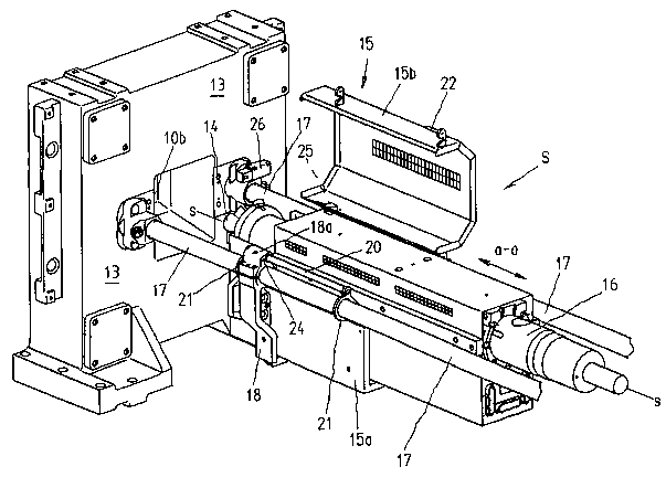
The invention relates to an injection molding machine that is provided with a
protective cover (15) that can be displaced from a non-protective to a
protective position by means of a handle (27) and that is used to cover the
injection molding nozzle during the injection process. Said protective cover
is axially configured in a substantially parallel position with respect to the
axis of injection (s-s) and can be displaced to a protective position. The
protective cover (15) comprises a lower part (15a) on which an upper part
(15b) is mounted so as to be swiveled about a substantially parallel swivel
axis (a-a) with respect to the axis of injection (s-s). Said lower part (15a)
and said upper part (15b) can be displaced together to a non-protective and to
a protective position, thereby combining a reliable support of the protective
cover with a good accessibility of the nozzle and the plastification cylinder.


French Abstract

La présente invention concerne une machine de moulage par injection comprenant un couvercle de protection (15) qui peut passer de la position de protection à la position de non protection, et inversement, au moyen d'une poignée (27). Ledit couvercle sert à recouvrir la buse d'injection lors de l'injection et peut passer de la position de protection à la position de non protection, et inversement, selon un mouvement axial, de manière essentiellement parallèle à l'axe d'injection (s-s). Le couvercle de protection (15) présente une partie inférieure (15a) à laquelle est fixée une partie supérieure (15b) autour d'un axe de pivotement (a-a) essentiellement parallèle à l'axe d'injection (s-s). La partie inférieure (15a) et la partie supérieure (15b) peuvent passer ensemble de la position de protection à la position de non protection, et inversement. Cela permet d'obtenir à la fois un positionnement fiable du couvercle de protection et une bonne accessibilité à la buse et au cylindre de plastification.

Claims

Note: Claims are shown in the official language in which they were submitted.


-7-
CLAIMS
1. Injection molding machine for the processing of plastics materials and
other plastici-
zable substances having
- an injection mold assembly (10), accommodated between mold carriers (12, 13)
in a
mold clamping area (R),
- an injection molding unit (S) for injecting the plasticizable substances
into a central
mold cavity (10a) of the injection mold assembly (10) along an axis of
injection (s-s),
- a plasticizing cylinder (16) accommodated in the injection molding unit (S),
- an injection nozzle (14) at the end of the plasticizing cylinder (16) facing
the injection
mold assembly (10), which nozzle is adjacent an injection opening (10b) in the
injec-
tion mold assembly (10) during the injection process,
- a protective cover (15) for covering the injection nozzle (14) in the
protective position
during the injection process, which cover can be transferred from and into the
protec-
tive position guided in an axial manner substantially parallel to the axis of
injection (s-
s),
characterized in that the protective cover (15) has a lower section (15a), on
which an up-
per section (15b) is mounted so as to be pivotable around a pivotal axis
(a-a,) which is disposed substantially parallel relative to the axis of
injection (s-s), and in
that lower section (15a) and upper section (15b) can be transferred together
from and
into the protective position.
2. Injection molding machine according to claim 1, characterized in that the
injection mold-
ing unit (S) has at least one support bracket (18), which at the same time is
for guiding
the protective cover.
3. Injection molding machine according to claim 2, characterized in that the
guide columns
(20) are mounted in the support bracket (18) for guiding the protective cover
(15) and for
displacement with the protective cover (15).
4. Injection molding machine according to claim 3, characterized in that one
of the guide
columns (20) simultaneously forms the pivotal axis (a-a).
5. Injection molding machine according to one of the claims 1 - 4,
characterized in that, for
guiding the protective cover (15), guide columns (20) are provided which
extend parallel

-8-
to guide braces (17), via which the injection molding unit (S) is mounted on
the stationary
mold carrier (13) so as to be detachable.
6. Injection molding machine according to one of the preceding claims,
characterized in
that, for guiding the protective cover (15), guide columns (20) are provided,
which slide
via sliding members (21 ) at a spacing above guide braces (17), via which the
injection
molding unit (S) is secured on the stationary mold carrier (13) so as to be
detachable.
7. Injection molding machine according to claim 6, characterized in that the
guide braces
(17) pass through the circular sliding members (21) and the spacing between
the circular
sliding members and the guide braces (17) is such that, when the protective
cover is put
under load, the sliding members (21) come to abut against the guide braces
(17).
8. Injection molding machine according to claim 6 or 7, characterized in that
the sliding
members are disposed at least at the ends of the guide columns (20).
9. Injection molding machine according to one of the preceding claims,
characterized in that
upper section (15b) and lower section (15a) are interlocked for displacement
together.
10. Injection molding machine according to one of the preceding claims;
characterized in that
the upper section (15b), or respectively the lower section (15a), has at least
one locking
pin (22), which extends in the direction of the axis of injection (s-s) and
interacts with a
recess (24) on the lower section (15a), or respectively upper section (15b),
and in that,
for unlocking purposes, the upper section, or respectively lower section, is
displaceable
in the direction of the axis of injection relative to the lower section, or
respectively the up-
per section, before the upper section (15b) can be pivoted around the pivotal
axis (a-a).
11. Injection molding machine according to claim 10, characterized in that the
recess (24) is
provided on a sliding member (21), which is displaceable together with the
protective
cover (15), and/or on an integral profile (18a) of the support bracket (18)
supporting the
guide column (20).
12. Injection molding machine according to one of the preceding claims,
characterized in
that a switching member (25) is provided on the protective cover (15), which
switching
member is in active communication with a switch (26) disposed on the
stationary mold

-9-
carrier (13) and interrupts the operation of the injection molding unit (S)
when the protec-
tive cover (15) is transferred out of the protective position.

Description

Note: Descriptions are shown in the official language in which they were submitted.


CA 02387729 2002-04-16
-1-
Infection molding machine with a protective cover
Description
Reference to related applications
The present application claims the priority of German patent application 199
49
958.6, filed on 16.10.1999, the disclosure content of which is hereby also
expressly
made the subject of the present application.
Field of the invention
The invention relates to an injection molding machine for the processing of
plastics
materials and other plasticizable substances having a protective cover for the
injec-
tion nozzle in accordance with the main preamble of claim 1.
State of the art
The pamphlet "Synergy, interaction of forces" by Netstal-Maschinen AG, 8752
NafeIsISwitzerland makes known an injection molding machine with this type of
noz-
zle protection. The nozzle protection is displaceable in the direction of the
axis of
injection and runs on rails, which at the same time serve to enable the nozzle
to be
positioned on the stationary mold carrier. Guide braces are secured to the
stationary
mold carrier for this purpose. However, there is no protection against an
attack from
underneath. In addition, the cover is simply placed loosely in position, which
means
that vibrations can cause it to shake itself loose and, consequently, it does
not pro-
vide any reliable protection.
The disposing of nozzle protection of this type is also known, where there is
a lower,
fixed section as well as an upper section, which can be removed from the lower
sec-
tion. The fixed arrangement of the nozzle protection makes it difficult to
access the
nozzle and the plasticizing cylinder.

CA 02387729 2002-04-16
-1a-
A protective arrangement for a plastics material injection moulding machine
having at
feast two injection moulding units is known in DE 1 234 975 B. As the usual
axially dis-
placeable protective arrangement can no longer cover the nozzle region
properly in this
case, adaptors are provided here for the extension of the braces, via which
the second
injection moulding unit, standing vertically, is supported. A two-part
protection, which is
1o disposed in a fixed manner in the axial direction, is disposed on these
extension pieces.
One of the two parts can certainly be pivoted out around a hinge joint.
IS
25
35
AMENDED PAGE

CA 02387729 2002-04-16
Summary of the invention
-2-
Proceeding from the state of the art, it is the object of the present
invention to provide
an injection molding machine with nozzle protection, which combines reliable
protec-
tion with good accessibility.
This object is achieved through an injection molding machine with the
characteristics
of claim 1.
The protective cover comprises an upper section and a lower section, which
prefera-
bly surround the nozzle entirely. Where required, upper and lower section can
be
transferred out of and into the protective position together, which means that
good
accessibility is guaranteed, which can be increased even more by the upper
section
being pivotable relative to the lower section. This simplifies, for example,
the re-
moval of the plasticizable cylinder, it also being possible, at the same time,
to remove
the whole protective cover when work on the nozzle is to be carried out.
Further advantages can be found in the sub claims.
Short description of the Figures
The invention is described in more detail below by way of an exemplified
embodi-
ment. In which:
Figure 1 is a front view of an injection molding machine,
Figure 2 is an enlarged, three-dimensional view of plasticizing cylinder and
stationary mold carrier with the protective cover in the closed position,
Figure 3 is a representation as in Figure 2 with the protective cover pushed
back and the plasticizing cylinder retracted,
Figure 4 is a representation as in Figure 3 with the upper section of the
protec-
tive cover in the pivoted position,
Figure 5 is a three-dimensional representation to illustrate the design of the
protective cover.

CA 02387729 2002-04-16
-3-
Detailed description of preferred exemplified embodiments
The invention is now described in more detail as an example with reference to
the
enclosed drawings. The exemplified embodiments are certainly only examples,
which are not to limit the inventive concept to a specific arrangement.
Figure 1 shows an injection molding machine, which is for the processing of
plastics
materials and other plasticizable substances, such as ceramic or powdery sub-
stances. The injection molding machine has a mold closing unit F and an
injection
molding unit S on a machine foot 19. An injection mold assembly 10 is accommo-
dated in the mold closing unit in a mold clamping area R between the
displaceable
mold carrier 12 and the stationary mold carrier 13. The injection mold
assembly has
a central mold cavity 10a, into which the injection molding unit S injects the
plastici-
zable substances along an axis of injection s-s. A plasticizing cylinder 16 is
accommodated in the injection molding unit S itself.
As shown in Figure 4, an injection nozzle 14 is disposed at the front of the
injection
molding unit S at the end of the same facing the injection mold assembly 10,
which
injection nozzle comes to rest at an injection opening 10b of the injection
mold as-
sembly 10 during the injecting process. The injection nozzle 14 can only be
seen in
Figure 4 as normally it is covered by a protective cover15 at least during the
injecting
process. The protective cover, guided in an axial manner substantially
parallel to the
axis of injection, can be transferred into and out of the protective position.
The protective cover 15 has a lower section 15a, in which an upper section
15b, as
can be seen in Figure 4, is mounted so as to be pivotable around a pivotal
axis,
which is disposed substantially parallel to the axis of injection s-s.
Nevertheless,
lower section 15a and upper section 15b can be transferred together out of the
pro-
tective position as in Figure 2 and out of the protective position as in
Figure 3.
Guide columns 20 are used as guiding members and are mounted on the support
bracket 18 via ball boxes and shafts (seen the best in Figure 5). The entire
lower
section, and consequently the upper section 15b connected thereto, is also
mounted
on this support bracket via these guide columns. Other members can also be pro-
vided in place of the support bracket. It is also possible to use other
members for the
guiding, such as, for example, the guide braces themselves.

CA 02387729 2002-04-16
-4-
The injection molding unit S can be supported on the machine foot via the
support
bracket 18. In the exemplified embodiment, the only object of the support
bracket,
which is not connected to the machine foot 9 in this case, is as guiding
member for
the plasticizing unit and as mounting support for the guide columns 20. This
also
enables the injection mold unit S to pivot without any problems. The guide
columns
20 are mounted in an integral profile 10a of the support bracket, one of which
guide
columns at the same time forming the pivotal axis a-a. As can be seen in
Figures 3
- 5, the guide columns extend parallel relative to the guide braces 17, via
which the
injection molding unit S is secured in a detachable manner on the stationary
mold
carrier 13. The guide columns 20 themselves are loosely connected also to the
guide braces via sliding members 21. Figure 5 shows the gap between the
sliding
members 21 and the guide braces. The guide braces 17 pass through these
circular
sliding members 21 and retain this gap in such a manner that the sliding
members 21
can come to rest on the guide braces 17 when the protective cover 15 is put
under
stress. In the exemplified embodiment, moreover, the sliding members 21 are
dis-
posed at the ends of the guide columns 20. In this way they are able to cope
with the
normal stress on the protective cover when moving into and out of the
protective po-
sition. However, to achieve overload protection, the sliding members, which
retain
the gap between the protective cover and the guide braces, are provided so
that
where there is a corresponding stress, this gap can be easily overcome by
releasing
the mounting of the guide columns.
When the unit is displaced, the following displacement sequence occurs:
Commencing with the position as shown in Figure 2, in which the guide column
20 is
abutting the integral profile 18a with its rear end, the protective cover 15
is trans-
ferred into the position shown in Figure 3. To achieve this, the front sliding
member
21 moves to abut the support bracket 18. The entire protective cover 15 is
neverthe-
less at this time only guided in the integral profiles 18a, this displacement
causing the
guide column 20, as can be seen when comparing Figure 2 and Figure 3, to be
pushed through the integral profile 18a. This displacement produces at the
most a
loose contact between sliding member 21 and guide brace 17. If, however, an ex-
ternal stress is applied to the protective cover, for example, if a user puts
his foot on
the protective cover, it would be impossible for the ball boxes and shafts in
the inte-
gral profile 18a of the support bracket to cope. At this time, the gap between
sliding
member 18 and guide brace 17 is reduced such that one abuts the other and addi-
tional supporting of the protective cover on the guide braces17 is achieved.

CA 02387729 2002-04-16
-5-
Figures 4 and 5 show how upper section 15b and lower section 15a are
interlocked
to enable them to be displaced together. The upper section 15b has a locking
pin 22
extending in the direction of the axis of injection s-s. This locking pin
interacts with a
recess 24 of the support bracket 18. Before the upper section 15b of the
protective
cover 15 can be pivoted, the locking pin 22 must be removed from the recess 24
of
the support bracket 18 by pushing back the protective cover. The mounting of
the
upper section 15b can also be configured such that a relative displacement
between
upper section 15b and lower section 15a is necessary tv release the locking
pin 22,
for example, from a recess in the lower section 15a. Where required, suitable
locking
mechanisms, which require a conscious unlocking procedure before the upper sec-
tion 15b can be pivoted, can be provided either on a supporting member 18, on
an-
other arbitrary member suitable for this or on the lower section.
Figure 4 shows a safety mechanism which puts the injection molding unit out of
ac-
tion as soon as the protective cover 15 is moved out of its protective
position, as
shown in Figure 2. To this end, a switch 26, such as, for example, an approach
switch, is provided, which records whether the protective cover 15 is located
abutting
against the stationary mold carrier 13. The switch 26, in the exemplified
embodi-
ment, is disposed in the connecting region of the guide braces, it can,
however, also
be mounted on the stationary mold carrier. In addition, as shown in Figure 4,
a
switching member 25, in the form of a switching finger, is used, which takes
care of
the corresponding contacting.
It goes without saying that this description can be subject to the most varied
modifi-
cations, changes and adaptations, which vary in the region of equivalents to
the at-
tached sub claims.

CA 02387729 2002-04-16
-6-
Reference list (Not a part of the application documents)
10 Injection mold assembly
10a Central mold cavity
10b Injection opening
11 Carrier block
12 Displaceable mold carrier
13 Stationary mold carrier
14 Injection nozzle
Protective cover
15a Lower section
15 15b Upper section
16 Plasticizing cylinder
17 Guiding brace
18 Support bracket
18a Integral profile
19 Machine foot
20 Guide column
21 Sliding member
22 Locking pin
23
24 Recess
25 Switching member
26 Switch
27 Handle
a-a Pivotal axis
3o s-s Axis of injection
F Mold closing unit
R Mold clamping area
S Injection molding unit

Representative Drawing
A single figure which represents the drawing illustrating the invention.
Administrative Status

2024-08-01:As part of the Next Generation Patents (NGP) transition, the Canadian Patents Database (CPD) now contains a more detailed Event History, which replicates the Event Log of our new back-office solution.

Please note that "Inactive:" events refers to events no longer in use in our new back-office solution.

For a clearer understanding of the status of the application/patent presented on this page, the site Disclaimer , as well as the definitions for Patent , Event History , Maintenance Fee  and Payment History  should be consulted.

Event History

Description Date
Application Not Reinstated by Deadline 2006-10-10
Time Limit for Reversal Expired 2006-10-10
Deemed Abandoned - Failure to Respond to Maintenance Fee Notice 2005-10-11
Amendment Received - Voluntary Amendment 2004-01-19
Letter Sent 2003-12-30
All Requirements for Examination Determined Compliant 2003-12-04
Request for Examination Received 2003-12-04
Request for Examination Requirements Determined Compliant 2003-12-04
Inactive: Cover page published 2002-10-02
Inactive: Notice - National entry - No RFE 2002-09-30
Inactive: Inventor deleted 2002-09-30
Application Received - PCT 2002-07-05
National Entry Requirements Determined Compliant 2002-04-16
Application Published (Open to Public Inspection) 2001-04-26

Abandonment History

Abandonment Date Reason Reinstatement Date
2005-10-11

Maintenance Fee

The last payment was received on 2004-07-29

Note : If the full payment has not been received on or before the date indicated, a further fee may be required which may be one of the following

  • the reinstatement fee;
  • the late payment fee; or
  • additional fee to reverse deemed expiry.

Patent fees are adjusted on the 1st of January every year. The amounts above are the current amounts if received by December 31 of the current year.
Please refer to the CIPO Patent Fees web page to see all current fee amounts.

Fee History

Fee Type Anniversary Year Due Date Paid Date
Basic national fee - standard 2002-04-16
MF (application, 2nd anniv.) - standard 02 2002-10-10 2002-04-16
MF (application, 3rd anniv.) - standard 03 2003-10-10 2003-07-11
Request for examination - standard 2003-12-04
MF (application, 4th anniv.) - standard 04 2004-10-11 2004-07-29
Owners on Record

Note: Records showing the ownership history in alphabetical order.

Current Owners on Record
KARL HEHL
Past Owners on Record
None
Past Owners that do not appear in the "Owners on Record" listing will appear in other documentation within the application.
Documents

To view selected files, please enter reCAPTCHA code :


To view images, click a link in the Document Description column. To download the documents, select one or more checkboxes in the first column and then click the "Download Selected in PDF format (Zip Archive)" or the "Download Selected as Single PDF" button.

List of published and non-published patent-specific documents on the CPD .

If you have any difficulty accessing content, you can call the Client Service Centre at 1-866-997-1936 or send them an e-mail at CIPO Client Service Centre.


Document
Description 
Date
(yyyy-mm-dd) 
Number of pages   Size of Image (KB) 
Representative drawing 2002-04-15 1 30
Description 2002-04-15 7 283
Abstract 2002-04-15 1 26
Drawings 2002-04-15 5 138
Claims 2002-04-15 3 118
Notice of National Entry 2002-09-29 1 192
Acknowledgement of Request for Examination 2003-12-29 1 188
Courtesy - Abandonment Letter (Maintenance Fee) 2005-12-05 1 174
PCT 2002-04-15 15 534