Language selection

Search

Patent 2387852 Summary

Third-party information liability

Some of the information on this Web page has been provided by external sources. The Government of Canada is not responsible for the accuracy, reliability or currency of the information supplied by external sources. Users wishing to rely upon this information should consult directly with the source of the information. Content provided by external sources is not subject to official languages, privacy and accessibility requirements.

Claims and Abstract availability

Any discrepancies in the text and image of the Claims and Abstract are due to differing posting times. Text of the Claims and Abstract are posted:

  • At the time the application is open to public inspection;
  • At the time of issue of the patent (grant).
(12) Patent Application: (11) CA 2387852
(54) English Title: MICRONIZING DEVICE AND METHOD FOR MICRONIZING SOLID PARTICLES
(54) French Title: DISPOSITIF DE MICRONISATION ET PROCEDE DE MICRONISATION DE PARTICULES SOLIDES
Status: Deemed Abandoned and Beyond the Period of Reinstatement - Pending Response to Notice of Disregarded Communication
Bibliographic Data
(51) International Patent Classification (IPC):
  • B02C 19/06 (2006.01)
  • B02C 7/04 (2006.01)
(72) Inventors :
  • NIEMI, JOUKO (Finland)
  • ILMASTI, VEIKKO (Finland)
  • SUOMINEN, HANNU (United States of America)
(73) Owners :
  • MICROPULVA LTD. OY
  • BCDE GROUP WASTE MANAGEMENT LTD. OY
(71) Applicants :
  • MICROPULVA LTD. OY (Finland)
  • BCDE GROUP WASTE MANAGEMENT LTD. OY (Finland)
(74) Agent: MCCARTHY TETRAULT LLP
(74) Associate agent:
(45) Issued:
(86) PCT Filing Date: 2000-10-19
(87) Open to Public Inspection: 2001-04-26
Availability of licence: N/A
Dedicated to the Public: N/A
(25) Language of filing: English

Patent Cooperation Treaty (PCT): Yes
(86) PCT Filing Number: PCT/FI2000/000910
(87) International Publication Number: WO 2001028690
(85) National Entry: 2002-04-18

(30) Application Priority Data:
Application No. Country/Territory Date
09/422,334 (United States of America) 1999-10-21

Abstracts

English Abstract


The invention concerns a micronizing device comprising a grinding housing with
an outlet opening at one end, two coaxially positioned rotatably driven hollow
axles entering the grinding house through two opposite side walls thereof,
each of said axles having an inner end provided with a conically enlarging
disc defining a grinding chamber, a circumferential outlet gap being formed
between said discs, each disc being provided with at least one concentrically
positioned ring of axially directed taps or wings near the circumference of
the disc, the rings having different diameters, so that said discs can be
driven to rotate in opposite directions, two acceleration nozzles are brought
into the grinding chamber through the hollow axles, said nozzles being
directed towards a common point in the grinding chamber away from a center
point of said grinding chamber. The invention concerns also a method using
said device.


French Abstract

L'invention concerne un dispositif de micronisation comprenant un compartiment de broyage dont une extrémité est pourvue d'une ouverture de sortie, deux axes creux à entraînement rotatif placés de manière coaxiale et pénétrant dans ce compartiment de broyage à travers deux parois latérales, chacun desdits axes possédant une extrémité interne pourvue d'un disque à élargissement conique définissant une chambre de broyage, une fente de sortie circonférentielle étant ménagée entre ces disques, chaque disque étant pourvu d'au moins un anneau concentrique de prises ou d'ailettes orientées axialement au voisinage de la circonférence du disque, ces anneaux présentant des diamètres différents, de façon que les disques puissent être entraînés et tourner dans des sens opposés. Deux buses d'accélération sont amenées dans la chambre de broyage par l'intermédiaire des axes creux, ces buses étant dirigées vers un point commun dans la chambre de broyage dans un sens opposé à un point central de cette chambre. L'invention concerne également un procédé utilisant ce dispositif.

Claims

Note: Claims are shown in the official language in which they were submitted.

6
CLAIMS
1. Micronizing device comprising a grinding housing with an
outlet opening at one end, two coaxial positioned ratably driven
hollow axles entering the grinding house through two opposite side
walls thereof, each of said axles having an inner end provided with
a conical enlarging disc defining a grinding chamber, a circum-
ferential outlet gap being formed between said discs, each disc
being provided with at least one concentrically positioned ring of
axially directed taps or wings near the circumference of the disc,
the rings having different diameters, so that said discs can be
driven to rotate in different speed or in opposite directions, two
acceleration nozzles are brought into the grinding chamber through
the hollow axles, said nozzles being directed towards a common point
in the grinding chamber away from a center point of said grinding
chamber, depending upon the application.
2. Micronizing device according to claim 1, wherein the discs are
provided with a reinforcing annular inner surface covering a region
facing the opposed acceleration nozzle during the rotation of said
disc.
3. Micronizing device according to claim 1, wherein the
acceleration nozzles are fed with solid particles fluidized with
pressurized power gas.
4. Micronizing device according to claim 1, wherein in each disc
is provided with an outermost ring of axial wings.
5. Micronizing device according to claim 1 wherein in each hollow
axle there is a solid static cylindrical piece through which the
acceleration nozzle is extended.
6. Method for micronizing solid particles fluidized in a pres-
surized power gas comprising the steps of accelerating a fluidized
solid-gas suspension through two opposedly directed acceleration
nozzles into a grinding chamber, wherein the solids are ground on
colliding against one another between two opposed conical discs
rotating in different speed or in different directions, during
escaping from the grinding chamber through a circumferential gap.

between the discs the thus ground gas/solid suspension is
mechanically further ground by means of taps and/or wings extending
axially from a circumferential inner surface of both oppositely
rotating discs, and such a further ground solid-gas suspension will
then leave a grinding house surrounding said discs through an outlet
opening.
7. Method according to claim 6 wherein the pressure of the power
gas and the solid content in the solid-gas suspension are adjusted
to receive optimal micronization of a fine fraction and the shape
and number of taps as well as the rate of rotation of the discs are
adjusted to regulate optimal mechanical grinding of any coarse
particles passing through the gap between said discs.
8. Method according to claim 6 wherein the material to be micro-
nized is pyrolized carbon from old car tires.
9. Method according to claim 8 wherein steel from the tire has
been removed by magnetic separation from the pyrolized carbon.
10. Method according to claim 6 wherein the oppositely rotating
discs provided with axial wings act as a fan evacuating gas and
ground products from and lowering the pressure in the space between
the discs.

Description

Note: Descriptions are shown in the official language in which they were submitted.


CA 02387852 2002-04-18
WO 01/28690 PCT/FI00/00910
Micronizing device and method for micronizing solid particles.
BACKGROUND OF THE INVENTION
This invention refers to a micronizing device and a method for
micronizing solid particles fluidized in a pressurized power gas.
All industrial fields from medical industry to mine- and building
material industry use as raw materials a continuously increasing
amount of different types of finely ground or micronized powder like
dry products. The micronizing / fine-grinding of these products is
nowadays generally carried out in jet mills, in which highly
pressurized air or overheated water vapor is generally used as
grinding energy. Depending on the final product and the fineness
thereof the energy consumption of these grinding and classifying
processes is about 100 to 3000 kWh/ton.
An effective and relatively economical micronizing method is a
technique operating according to the opposed jet mill principle. The
opposed jet mill technique was developed during the 1980:ies and the
1990:ies substantially by the Finnish company Oy Finnpulva Ab, by
means of which technique the energy economy and the grinding
effectiveness of the fine grinding have been improved considerably.
However, a wider utilization and application of the developed
opposed jet mill technique has been considerably disturbed by the
lack of effective auxiliary techniques applicable in connection with
that technique and/or their low efficiency and high energy costs.
In fine-grinding/micronizing a high-energy power gas, most often
pressurized air, is used as grinding energy. The micronizing
devices will need industrial compressor effects ranging from 100 kW
to 1000 kW depending upon application.
A drawback of previously known micronizing devices and methods is
the considerably increasing energy consumption if the counter jet
mill is adjusted to concentrate the grinding to eliminate particles
having a particle size over 10 lun. Further the pressure of the
power gas has to be considerably high because an elevated pressure
must be maintained in the jet mill in order to force the ground
solid-gas suspension to a classifier and further treatment steps.

WO 01/28690 2 PCT/FI00/00910
It is, therefore, an object of the present invention to eliminate
the above drawbacks by providing a new and improved micronizing
device.
It is another object of the present invention to provide a new and
improved method for micronizing solid particles fluidized in a
pressurized power gas having no one of the above drawbacks.
SUMMARY OF THE INVENTION
In accordance with the present invention there is provided a
micronizing device comprising a grinding housing with an outlet
opening at one end, two coaxial positioned rotatable driven hollow
axles entering the grinding house through two opposite side walls
thereof, each of said axles having an inner end provided with a
conical enlarging disc defining a grinding chamber, a circum-
ferential outlet gap being formed between said discs, each disc
being provided with at least one concentrically positioned ring of
axially directed taps and/or wings near the circumference of the
disc, the rings having different diameters, so that the discs can be
driven to rotate in opposite directions. Two acceleration nozzles
are brought into said grinding chamber through said hollow axles,
said nozzles being directed towards a common point in the grinding
chamber away from a center point of said grinding chamber.
By means of such a micronizing device the pressure of the fluidized
gas-solid suspension can be lowered without affecting the grinding
result because the pressure in the grinding chamber is lowered due
to a fan effect of the appositely rotating wings and taps at the
discs. Further said taps and wings can be adjusted to mechanically
grind possible coarser particles, having a particle size over l0~un,
passing the gap between the two discs, with considerably smaller
energy consumption as required in a conventional opposed jet mill
technique. In a micronizing device according to the present
invention the gas volume to be circulated is considerably smaller
than in a conventional opposed jet mill resulting in still improved
energy economy.
In accordance with the invention there is also provided a method for
micronizing solid particles fluidized in a pressurized power gas
comprising the steps of accelerating a fluidized solid-gas suspen-
sion through two opposedly directed acceleration nozzles into a
CA 02387852 2002-04-18

CA 02387852 2002-04-18
WO 01/28690 3 PCT/FI00/00910
grinding chamber, wherein the solids are ground on colliding against
one another between two opposed conical discs rotating in different
directions, during escaping from the grinding chamber through a
circumferential gap between the discs the thus ground gas/solid
suspension is mechanically further ground by means of taps and/or
wings extending axially from a circumferential inner surface of
both oppositely rotating discs, and such a further ground solid-gas
suspension will then leave a grinding house surrounding said discs
through an outlet opening.
Further features of the invention will appear from the attached
dependent claims.
BRIEF DESCRIPTION OF THE DRAWINGS
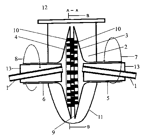
FIG. 1 is a schematical vertical section A-A a micronizing device
according to the invention;
FIG. 2 is a vertical section B-B through the micronizing device in
FIG. 1 .
DESCRIPTION OF A PREFERRED EMBODIMENT
The material to be ground/micronized is fluidized with a pressurized
power gas, such as air and a fluidized solid-gas suspension if
accelerated through two acceleration opposedly directed accelerating
nozzles 1 into a grinding chamber 2, defined by a pair of opposed
conical discs 3 and 4. The acceleration nozzles 1 are directed
toward a common point in the grinding chamber 2 away from the center
point of said grinding chamber. This will prevent solids accele-
rated and flowing out of one acceleration nozzle 1 to enter the
opposed acceleration nozzle 1, which would cause considerable
abrasive defects in the latter. The solids are ground on colliding
against one another. Said conical discs 3 and 4 are mounted on two
coaxial hollow axles 5 and 6 driven to rotate in opposite directions
as indicated by arrow 7 and 8. The conical discs 3 and 4 are
positioned at a distance from each other forming a circumferential
outlet gap 9 between them. Each disc 3 and 4 is provided with at
least one concentrically positioned ring of axially directed taps 10
or wings near the circumference of the disc 3 and 4 and extending
across said outlet gap 9. The diameter of each ring of taps 10 or
wings is different enabling the conical discs 3 and 4 to rotate in
opposite directions. The discs 3 and 4 are surrounded by a grinding

WO 01/28690 4 PCT/FI00/00910
house 11 provided with an outlet opening 12 at one end. The hollow
axles 5, 6 of the conical discs 3, 4 enters the grinding house 11
through two opposite sidewalls of said grinding house 11. The
gas/solid suspension ground in the grinding chamber 2 will escape
through said circunferential outlet gap 9. On passing through the
gap 9 the ground gas/solid suspension will be mechanically further
ground by means of said axially directed taps 10 or wings rotating
together with the conical discs 3 and 4. Simultaneously said taps
and wings will act as a fan decreasing the pressure in the grinding
chamber and forcing the further ground gas/solid suspension out of
the grinding house 11 to further treatment steps.
The reduced pressure in the grinding chamber 2 will positively
increase the grinding result on maintaining the initial pressure of
the power gas. For instance if the pressure in the grinding chamber
is lowered by 0.5 bar the grinding efficiency will increase by more
than 10 %.
In order to protect the discs 3 and 4 defining the grinding chamber
2 against abrasion, each disc 3 and 4 is provided with a reinforcing
annular inner surface covering a region which will face the opposed
acceleration nozzle 1 during the rotation of said disc.3, 4.
The effectiveness of the micronizing device can further be adjusted
by changing the number of concentric rings of axially extending taps
10 or wings at both discs 3, 4 as well as by varying the rate of
rotation of said discs. In order to receive a possibly good fan
effect in the micronizing device it is preferred to have an outer-
most ring of axially extending wings at both discs 3, 4.
According to a preferred embodiment a solid static cylindrical metal
piece 13 is inserted in the hollow axles 5, 6, through which metal
piece the acceleration nozzle 1 is extended.
A most optimal grinding result will be received if the pressure of
the power gas and the solid content in the solid/gas suspension are
adjusted to receive optimal micronization of a fine fraction and the
shape and number of the taps 10 or wings as well as the rate of
rotation of the discs 3, 4 are adjusted to regulate optimal
mechanical grinding of any coarse particles passing trough the
circumferential gap 9 between said discs 3, 4.
CA 02387852 2002-04-18

WO 01/28690 5 PCT/FI00/00910
Due to these effects a better and controllable grinding result will
be achieved by less grinding energy than in conventional grinding.
The micronizing device according to the present invention can be
used for instance in micronizing pyrolized carbon from old car
tires, from which carbon steel has been removed by using a magnetic
separator. Further the micronizing device can be used in the
medical, and in the food industry as well as in the paint and
building industry.
CA 02387852 2002-04-18

Representative Drawing
A single figure which represents the drawing illustrating the invention.
Administrative Status

2024-08-01:As part of the Next Generation Patents (NGP) transition, the Canadian Patents Database (CPD) now contains a more detailed Event History, which replicates the Event Log of our new back-office solution.

Please note that "Inactive:" events refers to events no longer in use in our new back-office solution.

For a clearer understanding of the status of the application/patent presented on this page, the site Disclaimer , as well as the definitions for Patent , Event History , Maintenance Fee  and Payment History  should be consulted.

Event History

Description Date
Application Not Reinstated by Deadline 2004-10-19
Time Limit for Reversal Expired 2004-10-19
Deemed Abandoned - Failure to Respond to Maintenance Fee Notice 2003-10-20
Letter Sent 2002-10-07
Inactive: Cover page published 2002-10-02
Inactive: Notice - National entry - No RFE 2002-09-30
Inactive: Single transfer 2002-07-11
Application Received - PCT 2002-07-08
National Entry Requirements Determined Compliant 2002-04-18
Application Published (Open to Public Inspection) 2001-04-26

Abandonment History

Abandonment Date Reason Reinstatement Date
2003-10-20

Maintenance Fee

The last payment was received on 2002-04-18

Note : If the full payment has not been received on or before the date indicated, a further fee may be required which may be one of the following

  • the reinstatement fee;
  • the late payment fee; or
  • additional fee to reverse deemed expiry.

Please refer to the CIPO Patent Fees web page to see all current fee amounts.

Fee History

Fee Type Anniversary Year Due Date Paid Date
Registration of a document 2002-04-18
Basic national fee - standard 2002-04-18
MF (application, 2nd anniv.) - standard 02 2002-10-21 2002-04-18
Owners on Record

Note: Records showing the ownership history in alphabetical order.

Current Owners on Record
MICROPULVA LTD. OY
BCDE GROUP WASTE MANAGEMENT LTD. OY
Past Owners on Record
HANNU SUOMINEN
JOUKO NIEMI
VEIKKO ILMASTI
Past Owners that do not appear in the "Owners on Record" listing will appear in other documentation within the application.
Documents

To view selected files, please enter reCAPTCHA code :


To view images, click a link in the Document Description column. To download the documents, select one or more checkboxes in the first column and then click the "Download Selected in PDF format (Zip Archive)" or the "Download Selected as Single PDF" button.

List of published and non-published patent-specific documents on the CPD .

If you have any difficulty accessing content, you can call the Client Service Centre at 1-866-997-1936 or send them an e-mail at CIPO Client Service Centre.


Document
Description 
Date
(yyyy-mm-dd) 
Number of pages   Size of Image (KB) 
Representative drawing 2002-04-18 1 11
Abstract 2002-04-18 1 60
Claims 2002-04-18 2 72
Description 2002-04-18 5 210
Drawings 2002-04-18 2 23
Cover Page 2002-10-02 1 45
Notice of National Entry 2002-09-30 1 192
Courtesy - Certificate of registration (related document(s)) 2002-10-07 1 109
Courtesy - Abandonment Letter (Maintenance Fee) 2003-12-15 1 177
PCT 2002-04-18 4 168
PCT 2002-04-19 3 145
Fees 2002-04-18 1 34