Note: Descriptions are shown in the official language in which they were submitted.
CA 02388178 2002-04-22
WO 01/31081 PCT/US00/29099
METHOD AND APPARATUS FOR COATING A SUBSTRATE IN A VACUUM
BACKGROUND OF THE INVENTION
1. Field of the Invention
The present invention relates to material coating
and, more particularly, to a method and apparatus for
coating a substrate with a deposition material in a vacuum.
2. Brief Description of the Prior Art
Coating a substrate with a deposition material
typically involves vaporizing the deposition material in a
vacuum such that the vaporized deposition material
condenses onto a substrate that is at a lower temperature
than the temperature of the vaporized deposition material.
In the production of organic-based devices, a
thin, flat, film-like substrate is coated with a chemical
coating, usually organic based, on at least one side of the
substrate. The substrate material may be glass or a
plastic/polymeric material and though typically planar in
configuration, may also consist of a curved or non-planar
surface. The size of the substrate being coated is
generally limited to a few square inches due to technical
capability limitations of current material sources.
During fabrication of most organic-based devices,
such as organic-based LED displays, organic-based lasers,
organic-based photo-voltaic panels, and organic-based
integrated circuits, chemicals or deposition materials are
typically applied to the substrate in a vacuum, using a
point source crucible A, shown in Fig. l, or a modified
point source crucible. When the chemicals are heated, the
chemicals vaporize and radiate away from the point source
crucible A, through an exit aperture B, in a generally
cosine-shaped emission plume C. A substrate D is then
typically held in a fixed position or rotated within the
emission plume C with a planar side E of the substrate D
facing the point source crucible A. A certain amount of
CA 02388178 2002-04-22
WO 01/31081 PCT/US00/29099
vaporized chemicals deposits on the planar side E of the
substrate D, forming a film coating.
In some applications, modified point sources are
used to produce a gaussian (non-uniform) flux distribution.
Examples of modified point sources include R.D. Mathis-type
boats, Knudsen cells, or induction furnace sources. A
general drawback of point or modified point source
crucibles, however, is their design. First, the ability to
control evaporation rates of chemicals involves sensitive,
precise control over material temperatures and temperature
gradients with low heat capacities and poor thermal
conductivity. Point sources/gaussian material sources
typically use radiant reflectors, insulation, and baffling
to create good evaporation rates for metals and salts at
higher temperatures of 1,000-2,000°C. However, these
material sources are inappropriate for evaporating organic-
based chemicals at lower temperatures of 100-600°C.
Excessive heat applied to many organic-based chemicals will
spit the chemicals out of the material sources, destroying
any film being grown on the substrate and requiring the
vacuum system to be taken out of service in order to be
cleaned and reloaded. Another problem is that the
vaporized chemicals frequently condense into the exit
apertures of the crucibles of point or modified point
sources. The condensation of the vaporized chemicals begins
to alter or occlude the exit aperture, causing chemicals to
fall back into the crucible's heated interior, and spit
onto the substrate. This spitting ruins the homogenous
distribution of the chemical film, because films having
spit defects exhibit higher surface roughness values and
may exhibit pinhole defects entirely through the deposited
layers. The source aperture condensation also degrades the
uniformity of the deposited film by altering the flux
emission distribution.
-2-
CA 02388178 2002-04-22
WO 01/31081 PCT/US00/29099
Another disadvantage of both point and modified
point source crucibles is that no axis of flux uniformity
can be found. Point source and modified point source
crucibles produce relatively uniform films only when flux
angles are kept small. As shown in Fig. 2, flux angles a,,
(3, and y are measured from a normal axis N extending from
the exit aperture of the point source crucible to lines L1,
L2, and L3 representing the edge of the cosine-shaped plume
C shown in Fig . 1 . The only way to keep the flux angle
small, such as the angle a shown in Fig. 2, is to greatly
increase the separation distance, or throw distance,
between the point source crucible A and the planar side E
of a substrate, such as those substrates referred to by
reference numerals D1, D2, and D3. For example, substrate
D2 would need to be moved to the position of substrate D3
to be fully coated, while keeping the flux angle a constant.
Such a move would increase the throw distance from TD2 to
TD3. Similarly, if substrate D3 is moved to the position
of substrate D1, i.e., from TD3 to TD1, then only a small
portion of substrate D3 would be coated, and the deposited
coating would be much less uniform. Film uniformity is a
very important characteristic of organic layers utilized
for photonic and electronic applications as the fabricated
devices will not operate properly, if at all, if the
organic-based films are not maintained at a 95 percent or
higher level of uniformity.
Throw distances can be predicted in order to
achieve a uniform film of 95 percent or higher. If this
uniformity requirement is applied to a 6-inch square
substrate, for example, then a throw distance of
approximately 2 1/2 feet may be required. By comparison,
a 24-inch square substrate would require a throw distance
of 9 1/2 feet. This increasing throw distance destroys the
ability to develop a productive process, because the rate
-3-
CA 02388178 2002-04-22
WO 01/31081 PCT/US00/29099
of film growth is inversely proportional to the square of
the distance between the crucible and the substrate.
Film growth rates of organic-based materials are
typically expressed in single Angstroms per second. For
example, a throw distance of one foot or less would be
desirable for coating a 12-inch substrate with a 95 percent
uniform film coating 1000 Angstroms thick. At the one-foot
throw distance, a typical chemical deposition rate would be
18 Angstroms per second, which equates to a coating time of
approximately fifty-five seconds. Conversely, at a throw
distance of 9 1/2 feet, the typical deposition rate is 2
Angstroms per second, resulting in a 1 1/2-hour deposition
time.
In addition to increasing film growth rates,
increases in throw distance significantly increase
production costs. First,. vacuum chambers must be large
enough to accommodate the increased throw distances,
requiring larger vacuum deposition chambers as well as more
powerful vacuum pumps. Second, there is a substantial
waste of expensive chemicals, since an increase in throw
distance decreases deposition efficiency. Third, because
the vaporized organic material that does not reach the
substrate is deposited on an interior wall of the vacuum
chamber, the vacuum chamber must be removed from productive
service and cleaned more frequently. Cleaning is expensive
because some chemicals, such as those used to produce
organic liquid electronic displays, are toxic as well as
expensive. Costs are further exaggerated because point or
modified point source crucibles only hold between 1 and 10
cubic centimeters of chemicals. Therefore, only a few
substrates can be coated before the vacuum chamber must be
brought to atmosphere, the vacuum chamber cleaned, the
crucibles refilled, and the vacuum chamber re-evacuated.
It is therefore an object of the present
invention to produce a method and apparatus for coating a
CA 02388178 2002-04-22
WO 01/31081 PCT/US00/29099
substrate in a vacuum that allows larger substrates to be
coated without increasing throw distances as the width of
a substrate increases, allowing more deposition material to
be deposited on the substrate during coating, reducing
loading downtime, and reducing cleaning time.
SUi~SARY OF THE INVENTION
In order to help solve the problems associated
with the prior art, the present invention generally
includes a vacuum deposition system for coating a substrate
with a deposition material. The vacuum deposition system
includes a vacuum chamber and a material source positioned
inside the vacuum chamber. The material source has a body
which extends along a longitudinal axis, a substantial
longitudinal emission component, and defines an interior
cavity and an exit aperture fluidly connected to the
interior cavity. A heat source is positioned adjacent to
the body of the material source.
A substrate to be coated, having a width measured
parallel to the longitudinal axis of the body, may be
positioned inside the vacuum chamber, wherein a throw
distance, measured between one side of the substrate and
the exit aperture, remains constant as the width of the
substrate increases. Preferably, the substantial
longitudinal component of the body of the material source
is equal to the width of the substrate or less than the
width of the substrate.
A deposition material is loaded into the interior
cavity of the body of the material source. The deposition
material is selected from the group including an organic-
based chemical and an organic-based compound. The
deposition material is heated by the heat source and
emitted through the exit aperture along the substantial
longitudinal emission component of the body of the material
source.
_5-
CA 02388178 2002-04-22
WO 01/31081 PCT/ZJS00/29099
The material source may have a body in the shape
of an open trough having two longitudinally extending
sidewalls and a pair of endwalls, wherein the
longitudinally extending sidewalls and the endwalls define
the interior cavity of the body. The body of the material
source may further define an upper end positioned adjacent
to the exit aperture and a base, with the heat source being
a heating coil having a greater number of heating elements
positioned at the upper end of the body than at the base of
the body. The exit aperture may extend continuously along
the substantial longitudinal emission component of the body
and ribs positioned in the internal cavity defined by the
body of the material source.
The material source may also have a first conduit
defining an internal cavity and a first exit aperture
fluidly connected to the internal cavity, wherein the body
is a second conduit received in the internal cavity of a
first conduit. The first exit aperture defined by the
first conduit may be aligned with the exit aperture defined
by the second conduit or, the first exit aperture defined
by the first conduit may be aligned in a non-coincident
configuration with the exit aperture defined by the second
conduit. Regardless of body type, a process control
apparatus may be connected to the body of the material
source.
One method of coating a substrate using a
material source and a vacuum chamber includes the steps of:
a. positioning the material source in the vacuum
chamber, the material source having a body which extends
along a longitudinal axis, has a substantial longitudinal
emission component, and defines an interior cavity and an
exit aperture fluidly connected to the interior cavity;
b. positioning a substrate in the vacuum chamber,
cpposite the exit aperture defined by the body of the
material source;
CA 02388178 2002-04-22
WO 01/31081 PCT/US00/29099
c. loading a deposition material in the interior
cavity defined by the body of the material source;
d. evacuating the vacuum chamber to create a
vacuum;
e. heating the deposition material in the
internal cavity of the body of the material source;
f. emitting vaporized deposition material along
the substantially longitudinal component of the body; and
g. moving the substrate through the vaporized
deposition material.
The substrate may be moved through the vaporized
deposition material at a constant velocity. When substrate
coating is complete, the substrates can move to another
process or the vacuum chamber can be opened, the coated
substrates removed, new substrates added, the vacuum
chamber re-evacuated, and the above process steps repeated.
One type of material source for use in vacuum
deposition of a deposition material onto a surface of a
substrate includes two bodies, such. as a point source
crucible, a modified point source crucible, or a
combination, with each of the two bodies defining an
interior cavity and at least one exit aperture fluidly
connected to the interior cavity and a heating element
positioned adjacent to each of the two bodies, wherein the
two bodies are aligned along a common longitudinal axis to
form a substantial longitudinal emission component. A
process control apparatus may be connected to one of the
two bodies of the material source, and the interior
cavities of the two bodies are configured to receive
deposition material selected from the group including an
organic-based chemical and an organic-based chemical
compound.
Another type of material source for use in vacuum
deposition of a deposition material onto a surface of a
substrate includes a bod;Y~ wh_ch extends a,~ong a
CA 02388178 2002-04-22
WO 01/31081 PCT/L1S00/29099
longitudinal axis, has a substantial longitudinal emission
component, an defines an interior cavity and at least one
exit aperture fluidly connected to the interior cavity and
a heat source positioned adjacent to the body of the
material source. The exit aperture may extend continuously
along the substantial longitudinal emission component of
the body and ribs may be positioned in the internal cavity
defined by the body of the material source. The material
source may have a body in the shape of an open trough
having two longitudinally extending sidewalls and a pair of
endwalls, wherein the longitudinally extending sidewalls
and the endwalls define the interior cavity of the body.
The material source may also include a first
conduit defining an internal cavity and a first exit
aperture fluidly connected to the internal cavity, wherein
the body is a second conduit received in the internal
cavity of a first conduit. The heat source is positioned
adj acent to the f first conduit or the second conduit , the
heat source including a first layer of heat conductive
electrical insulation, a second layer of conductive
material, and a third layer of heat conductive electrical
insulation. The first exit aperture defined by the first
conduit may be aligned with the exit aperture defined by
the second conduit or the first exit aperture defined by
the first conduit may be aligned in a non-coincident
configuration with the exit aperture defined by the second
conduit.
These and other advantages of the present
invention will be clarified in the Detailed Description of
the Preferred Embodiments taken together with the attached
drawings in which like reference numerals represent like
elements throughout.
BRIEF DESCRIPTION OF THE DRAWINGS
Fig. 1 is a side view of a prior art single point
source crucible;
_g_
CA 02388178 2002-04-22
WO 01/31081 PCT/US00/29099
Fig. 2 is a side view of a prior art single point
source crucible shown in Fig. 1 with increasingly larger
substrates positioned adjacent to the crucible;
Fig. 3 is a perspective cross-sectional view of
a material source according to one embodiment of the
present invention;
Fig. 4 is a cross-sectional end view of the
material source shown in Fig. 3;
Fig. 5 is a cross-sectional side view of the
material source shown in Figs. 3 and 4;
Fig. 6 is a top perspective view of an emission
plume axially extending along a substantially longitudinal
component of the material source shown in Figs. 3-5;
Fig. 7 is a top view of two material sources
shown in Fig. 5 positioned inside a vacuum chamber;
Fig. 8 is a side view of four material sources
shown in Figs. 5-7 positioned at offset angles inside a
vacuum chamber;
Fig. 9 is a top view of a plurality of material
sources according to a second embodiment of the present
invention;
Fig. 10 is a perspective view of a material
source according to a third embodiment of the present
invention;
Fig. 11 is a perspective view of a first conduit
with a resistive heating element positioned adjacent to an
exterior surface of the first conduit;
Fig. 12 is a cross-sectional end view of the
first conduit shown in Figs. 10-11 and a second conduit
positioned inside the first conduit; and
Fig. 13 is a cross-sectional side view of the
third embodiment material source shown in Fig. 10.
DETAILED DESCRIPTION OF THE PREFERRED EMBODIMENTS
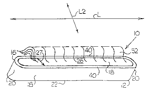
Figs. 3-8 show one embodiment of material source
10 in accordance with the present inventicn. Fig. 3 shows
CA 02388178 2002-04-22
WO 01/31081 PCT/US00/29099
a trough crucible 12 type of material source 10 for
evaporating deposition materials 14, such as organic
chemicals or organic compounds, or other suitable
materials. The trough crucible 12 generally includes an
elongated, open-topped body 16 extending about a
longitudinal axis L. As shown in Figs. 3 and 6, the body 16
preferably includes opposing longitudinal sidewalls 18,
opposing endwalls 20, and a base 22 formed together as a
unitary structure. The sidewalls 18 and endwalls 20
preferably have the same width W, as shown in Fig. 3, but
the sidewalls 18 preferably have a longer sidewall length
SL than the length EL of the endwalls 20, as shown in Fig.
7. Because the sidewalls 18 extend over a longer length SL
than the length EL of the endwalls 20, the body 16 has a
substantial longitudinal emission component, approximately
equal to the sidewall length SL and a smaller lateral
emission component, which is approximately equal to the
length EL of the endwalls 20. Moreover, the sidewalls 18 of
the trough crucible 12 are preferably longer than a
substrate 24 to be coated, as shown in Fig. 7, such as the
use of a 1S-inch length sidewall 18 for coating a 12-inch
square substrate 24.
Referring to Figs. 3-4, the sidewalls 18, the
endwalls 20, and the base 22 of the body 16 define an
internal cavity 26 and an exit aperture 27, with the base
22 of the body 16 further defining ribs 28, shown in Figs.
5 and 7, positioned adjacent to the internal cavity 26,
adjacent to a first surface 30 of the base 22, and
preferably extending between the sidewalls 18. The ribs 28
may be integrally formed into the body 16, such as by
machining, in order to further assist in the uniform
loading of deposition materials 14 into the trough crucible
12, as well as further collimating the vertical flux of the
trough crucible 12. As shown in Figs. 5 and 6, the ribs 28
deposition materials 14, such as organic material, in such
-1~-
CA 02388178 2002-04-22
WO 01/31081 PCT/US00/29099
a manner that the entire trough crucible 12 may be slightly
rotated about axis L2, even when loaded with a preferred
load of approximately 50 cubic centimeters to 100 cubic
centimeters of deposition materials 14. The body 16 and
ribs 28 are formed from a heat conducting material,
preferably a material that produces uniform heat
distribution. Ceramic is preferred, but metal or other
suitable materials are also acceptable. Various coatings
may be applied to the body 16 in order to enhance
durability and performance of the body 16.
As shown in Fig . 8 , the trough crucible 12 can
also be rotated slightly about the longitudinal axis L.
This allows multiple trough crucibles 12, each loaded with
different deposition materials 14 such as organic based
chemicals, to emit vaporized chemicals along a common
deposition axis 32. Different vaporous deposition
materials 14 can mix in a mixing zone 34 and be more evenly
distributed onto the substrate 24. An aperture 36 may be
used to target deposition materials 14 in the mixing zone
34 and restrict the passage of deposition materials 14 to
the substrate 24.
As shown in Figs. 3-4 and 7-8, heating elements
38 are positioned adjacent the body 16, preferably adjacent
the outer surface of the sidewalls 18, with a higher
concentration of heating elements 38 positioned adjacent an
upper edge 40 of each sidewall 18 adjacent to the exit
aperture 27. The higher concentration of heating elements
38 adjacent the upper edge 40 of each sidewall 18 helps
prevent re-crystallization of the vaporous deposition
materials 14. Similarly, by introducing a vertical
temperature gradient with a lower temperature at the base
22 of the trough crucible 12, spitting is reduced from
eruptions originating near the base 22. The heating
elements 38 are preferably surface mounted, but may also be
embedded cr ot'rerwise positioned adjacent to the sidewalls
-11-
CA 02388178 2002-04-22
WO 01/31081 PCT/US00/29099
18. Alternatively, the heat may be provided by heating
lamps (not shown), heating elements 38 positioned at a
distance from the sidewalk 18 of the trough crucible 12,
or induction.
As shown in Fig. 3, power supply leads 42 are
connected to the heating elements 38. A thermocouple
temperature sensing probe 44 is positioned adjacent to the
trough crucible 12 , preferably adj acent to the base 22 .
The thermocouple temperature sensing probe 44 is connected
to sensing equipment and other process control apparatus 45
that regulate the coating process.
With appropriate power control, the temperature
of the deposition materials 14 can be ramped to preset
values. With appropriate deposition materials 14 emission
monitoring, such as a quartz crystal motor head, the
deposition materials 14 may be throttled to preset rates of
deposition or emission. With more intelligent power
controllers and crystal sensors, pre-programmed thermal
routines may be set up in order to quickly degas and vacuum
prepare fresh deposition materials 14 loads for quick
turnaround of the trough crucible 12 type of material
sources 10.
In a second embodiment of the present invention,
shown in Fig. 9, the material source 10' includes a
plurality of point source crucibles 46 arranged along a
longitudinal axis L' in a linear array inside a vacuum
chamber 48 to create a substantially longitudinal emission
component which is approximately equal to the total length
LA of the linear array. Like the first embodiment material
source l0, the second embodiment provides a material source
10' which has a substantial longitudinal emission component
which is larger than a lateral component of the material
source. Each point source crucible 46 has a body 16'
forming an exit aperture 27', a heating element 38', power
3~ suoplv leads 42', and a thermocouple temperature sensing
-12-
CA 02388178 2002-04-22
WO 01/31081 PCT/US00/29099
probe 44'. The linear array pattern can roughly simulate
the linear output of the trough crucible 12 shown in Figs.
3-8 and is therefore useful for coating substrates 24
having a width W2 of more than a few inches. However, the
benefits are tempered by the known deficiencies, such as
spitting and multiple requirements for separate power
supplies, temperature displays, crystal heads, and feedback
and control loops.
A third embodiment of a material source 10" in
accordance with the present invention is generally shown in
Figs. 10-13. As shown in Fig. 10, the third embodiment
material source 10" includes a first conduit 56 or other
substantially hollow structure partially covered in an
optional heat shield 94. The first conduit 56 has two
opposing end sections 58, 60, defining at least one exit
aperture 27" . The first conduit 56 is supported by posts
62 or similar support fixtures or hardware attached to a
base 64. As shown in Fig. 11, a resistive heater element
74, such as a grid pattern, is positioned adjacent to an
exterior surface 76 of the first conduit 56.
As shown in Fig. 12, a second conduit 66 or other
structure defining an internal cavity fluidly connected to
an exit aperture is received in the internal cavity 68
defined by the first conduit 56. The second conduit 66,
which is configured to receive deposition material 14, such
as organic-based or other chemicals, generally defines a
second internal cavity 70 fluidly connected to a second
exit aperture 27' ' ' . The first conduit 56 and the second
conduit 66 are both made from ceramic or other suitable
material. A center axis C1 of the first conduit 56 may be
positioned coincident or eccentric with respect to a center
axis C2 of the second conduit 66. The second exit aperture
27" ' may be aligned with the exit aperture 27 " defined by
the first conduit 56 or, alternatively, the exit apertures
3~ 2~~ , , ?7"' ma;,,. be aligned in a nor.-ccinciden~ a~~ignec
-13-
CA 02388178 2002-04-22
WO 01/31081 PCT/US00/29099
configuration with the exit apertures 27" , 27" ' defined
by the first and second conduits 56, 66 not presenting a
line of sight path SP between the deposition materials 14
received by the second conduit 66 and the substrate 24. To
aid the alignment of the first conduit 56 and the second
conduit 66, optional support rods 72 made from quartz or
other suitable material may be extended between the
opposing end sections 58, 60 of the first conduit 56.
Additional second conduits 66 may also be housed within the
first conduit 56 to allow for the emission of multiple
chemicals.
Fig. l3 shows the third embodiment of the present
invention in more detail, with the grid type of resistive
heater element 74 replaced with a resistive heater element
74'. The resistive heater element 74' includes a first
layer 78 of heat conductive electrical insulation, such as
alumina, followed by a second resistive layer 80 of NiCr or
other suitable resistive conductive materials, followed by
a third layer 78' of heat conductive electrical insulation.
As previously noted above, heat shields 94 and insulating
buttons 96 can be positioned adjacent to the third layer of
heat conductive electrical insulation.
With continuing reference to Fig. 13, the first
and second conduits 56, 66 are nested together. One of the
opposing end sections 58 of the first conduit 56 is
removeably attached to an opposing end section 84 of the
second conduit 66, with the end section 84 of the second
conduit removeably attached to the second conduit 66. A
rod 88, surrounded by a bushing 90, extends through the end
section 58 of the first conduit 56 and the corresponding
opposing end section 84 of the second conduit 66. A second
rod 88, also surrounded by a bushing 90', extends through
the other opposing end section 60 of the first conduit 56
and the other corresponding opposing end section 86 of the
second condui,-_ 66. '~'~la ScCOnd ~"'Od ~~' ~S SuDDOY'~a~ ~V c
-14-
CA 02388178 2002-04-22
WO 01/31081 PCT/US00/29099
notched support arm 92 connected to the base 64. The heat
shields 92 and insulating buttons 94 used to position the
shields 92 were discussed earlier.
At least one electrode 98 extends through the
base 64 of the third embodiment material source 10" ,
electrically insulated from the base 64 by an insulating
material 100, such as ceramic or other suitable material.
The electrode 98 is connected to the resistive heating
element 74" to power leads 42. Electrical contact clamps
102 removeably attach the first conduit 56 to the electrode
98.
A material source according to any of the
embodiments of the present invention can be used to coat a
substrate 24, with the trough crucible 12 or hollow conduit
56" material source 10, 10" being preferred. For the
sake of clarity, only the first embodiment will be
described unless otherwise indicated.
In one method of operation, as shown in Figs. 7
8, the coating operation begins by positioning the
deposition materials 14 in the material source 10 and then
positioning one or more material sources 10 and one or more
substrates 24 into the vacuum chamber 48. The material
sources 10 should be positioned parallel to one another,
with the substrate axis 50 of each substrate 24 positioned
approximately perpendicular to the longitudinal axis L of
the parallel material sources 10.
An additional optional step is degassing the
material source 10, the vacuum chamber 48, and a desired
amount of deposition materials 14. For example, the
deposition materials 14 load for the trough crucible 12 is
generally 70 cubic centimeters to 100 cubic centimeters,
but may be increased or decreased depending on the size of
the material source 10.
The next step is evacuating the vacuum chamber 48
to the desired vacuum pressure, preferably less than 1~10~3~
-15-
CA 02388178 2002-04-22
WO 01/31081 PCT/US00/29099
Torr, and normally less than 9~10~-6~ Torr, or other suitable
vacuum pressure. Once a suitable vacuum is established, the
next step is heating the deposition materials 14 loaded in
one or more of the material sources 10 until the deposition
materials 14 vaporize and radiate a plume 52 of vaporized
deposition materials 14. Once the vaporization has begun,
the next step is moving the substrate 24 through the
linear-shaped plume 52 at a constant velocity v, as shown
in Figs. 7 and 8. Film deposition characteristics are
generally a growth rate of >=10 Angstroms per second with
film uniformity of >95 percent. The substrates 24 can be
moved by any suitable movement device, with an overhead
conveyer (not shown) being preferred.
In operation of the third embodiment material
source 10" of the present invention, the deposition
materials 14 are loaded into the second conduit 56 and are
heated by radiative heat transfer from an interior surface
82 of the first conduit 56. The deposition materials 14 are
vaporized and pass through the exit aperture or apertures
27" defined by the second conduit 66, through the exit
aperture 27"' or apertures defined by the first conduit
56, and then into the vacuum chamber 48. The exit aperture
27"' defined by the second conduit 66 may coincide with
the exit aperture 27" ', 27" defined by the first and
second conduits 56, 66 or may be in a non-coincident
aligned configuration wherein the exit aperture 27" ', 27 "
of the first and second conduits 56, 66 do not present a
line of sight SP between the deposition materials 14 and a
substrate 24.
As shown in Figs. 7 and 8 but generally
applicable to all of the embodiments, the linear design of
the material source 10 helps to guarantee film uniformity
out to the very edges 54 of the substrates 24 as the
substrates 24 are passed through vaporous deposition
16-
CA 02388178 2002-04-22
WO 01/31081 PCT/L1S00/29099
materials 14 plumes 52. However, if a trough crucible 12
or hollow conduit type of material source 10 is used,
uniformity is best achieved by making the sidewalk 18 (or
the conduit) longer in a longitudinal direction SL than a
width W2 of substrate 24. This is due to the presence of
reduced numbers of integrated gaussian flux emission angles
available to bolster the emission from the endwalls 20 of
the material source 10. The use of a variable exit
G~erture or hole dimensions may be used to offset this
effect and produce a more uniform emission across the
emission of the material source.
It should be apparent that the present invention
allows large substrates 24 to be coated with deposition
materials 14. This result is produced while generally
reducing deposition materials 14 waste, exposure to
potentially hazardous materials, the need for larger vacuum
chambers 48, coating time, and operating costs. Since the
present invention produces a vaporization plume that is
generally linear over a much longer longitudinal component
of the material source than the plume produced by a single
point or a modified point source, non-uniformities observed
with point sources and their associated cosine distribution
plumes are eliminated or greatly reduced. Moreover, rather
than increasing throw distances to several feet to achieve
95 percent uniformity levels, throw distances can be less
than 1 foot, regardless of the size of the surface area of
the side of the substrate to be coated.
Another feature of the present invention is that
the majority of available gaussian emission angles can be
used for deposition onto substrates passed over the
material source or sources at a constant velocity. This
results in a much greater percentage of chemicals deposited
directly onto the substrate, rather than unnecessarily
coating the internal surfaces of the vacuum chamber. This
reduces downtime and greatly reduces orgar~ic chemical costs
-17-
CA 02388178 2002-04-22
WO 01/31081 PCT/US00/29099
for each substrate that is coated. A related benefit is
that because the material source has a longer longitudinal
component than a single point or a modified point source,
more chemicals can be loaded into the material source,
resulting in less downtime in commercial applications as
the source may coat many more substrates between material
source refilling periods.
Flexibility is also enhanced because the material
source has standard feedthrough and power connections. Any
vacuum system currently capable of accepting linear sputter
material sources may be refitted with the material source
in that position. Vacuum systems which are also fitted
with 6-inch to 12-inch circular sputter sources may also
accept a material source of similar or like size.
Therefore, new vacuum systems need not be constructed in
order to obtain the organic deposition capability of the
present invention. The material source also lends itself
to placement in banks or arrays within a limited chamber
size. Several material sources may be readied with a
vacuum system such that when one material source runs out
of deposition materials, the next material source may be
used. Moreover, material spitting is virtually eliminated
from the trough crucible-type or the conduit-type of
material sources, due to lower thermal gradients and
crucible operating temperatures.
The invention has been described with reference
to the preferred embodiments. Obvious modifications and
alterations will occur to others upon reading and
understanding the preceding detailed description. It is
intended that the invention be construed as including all
such modifications and alterations insofar as they come
within the scope of the appended claims or the equivalents
thereof.
-18-