Language selection

Search

Patent 2388321 Summary

Third-party information liability

Some of the information on this Web page has been provided by external sources. The Government of Canada is not responsible for the accuracy, reliability or currency of the information supplied by external sources. Users wishing to rely upon this information should consult directly with the source of the information. Content provided by external sources is not subject to official languages, privacy and accessibility requirements.

Claims and Abstract availability

Any discrepancies in the text and image of the Claims and Abstract are due to differing posting times. Text of the Claims and Abstract are posted:

  • At the time the application is open to public inspection;
  • At the time of issue of the patent (grant).
(12) Patent Application: (11) CA 2388321
(54) English Title: HEARING DEVICE
(54) French Title: APPAREIL AUDITIF
Status: Deemed Abandoned and Beyond the Period of Reinstatement - Pending Response to Notice of Disregarded Communication
Bibliographic Data
Abstracts

English Abstract


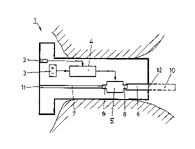
The invention relates to a hearing device comprising a microphone (2), a
signal processing unit (4), an earphone (5) with two openings (8,9) and an
energy storage unit (3). The microphone (2) is connected to the signal
processing unit (4) which is in turn connected to the earphone (5). Means
(7,12,10) are also provided to allow the acoustic signals produced in the
earphone (5) to be propagated from one of the openings (8) into the auditory
canal of the person wearing the hearing device. The invention is characterized
in that other means (6,11) are also provided to enable the second opening (9)
of the earphone (5) to be linked to the outside world when the hearing device
is inserted into the ear of the wearer.


French Abstract

L'invention concerne un appareil auditif comportant un micro (2), une unité de traitement de signal (4), un écouteur (5), qui présente deux ouvertures (8, 9), et une unité d'accumulation d'énergie (3). Le micro (2) est relié à l'unité de traitement de signal (4) qui est elle-même reliée à l'écouteur (5). En outre, des moyens (7, 12, 10) servent à la propagation des signaux acoustiques produits dans l'écouteur (5) dans le canal auditif de la personne portant l'appareil, à partir d'une ouverture (8). L'invention se caractérise par le fait que d'autres moyens (6, 11) servent à relier la seconde ouverture (9) de l'écouteur (5) avec le monde extérieur, lorsque ledit appareil auditif est inséré dans l'oreille de l'utilisateur.

Claims

Note: Claims are shown in the official language in which they were submitted.

-8-
Claims:
1. A hearing device, including a microphone (2), a signal-
processing unit (4), a speaker (5) with two orifices (8, 9)
and an energy-storage unit (3), which supplies the signal-
processing unit (4) and if need be the microphone (2) and
the speaker (5) with energy, where the microphone (2) is
connected to the signal-processing unit (4), which is
connected to the speaker (5), and where first means (7, 12,
10) are provided in such a way that acoustic signals
produced in the speaker (5) are transmitted from the one
orifice (8) into the auditory canal of the hearing device
wearer, characterized in that other means (6, 11) are
provided in such a way that the second orifice (9) in the
speaker (5) is connected to the outside world, and that the
dimensions or shape of the other means (11, 6) are chosen
in such a way that reflections of acoustic signals can be
avoided.
2. The hearing device according to claim 1, characterized
in that a direct connection from the outside world into the
auditory canal of the hearing device wearer is provided via
other means (11, 6), the speaker (5) and the first means
(7, 12, 10).
3. The hearing device according to one of the preceding
claims, characterized in that the first means (7, 10, 12),

-9-
with the help of which acoustic signals are transmitted
into the auditory canal, and/or the other means (6, 11) for
connecting the second orifice (9) of the speaker (5) are
connected to the outside world via tubular canals.
4. The hearing device according to claim 3, characterized
in that the other means (11, 6) made by means of the
tubular canal have a diameter from 0.5 to 2.0 mm.
5. The hearing device according to claim 3 or 4,
characterized in that the length of the means (11, 6) made
by means of the tubular canals is 24 mm.
6. The hearing device according to one of the preceding
claims, characterized in that on the end of the first means
(6) next to the auditory canal, a hook element (10) is
connected which has a hollow space for carrying acoustic
signals.
7. The use of the hearing device according to one of the
claims 1 to 6 as a BTE (behind the ear) hearing device.

Description

Note: Descriptions are shown in the official language in which they were submitted.


CA 02388321 2002-05-06
- 1 -
Hearing Device
This invention is related to a hearing device according to
the preamble of claim 1.
Hearing devices are used to equalize or compensate for
hearing problems in a patient by processing acoustic
signals picked up with a microphone that go through a
speaker in the patient's ear canal and are amplified or
changed. An acoustic outlet orifice (hole) is provided on
the hearing aid through which the acoustic signals produced
by the speaker are fed into the auditory canal.
It has long been known that the acoustic outlet orifice is
often reduced in size or even plugged up completely with
deposits, so-called earwax. Moreover, these deposits spread
out further into the inside of the hearing device, and get
into the inside of the speaker or the orifice. The result
of this is that the transmission properties of the hearing
device change. In addition, irreparable damage often occurs
to the individual components of the hearing device, and
especially to the speaker itself.
A hearing device is known from EP-0 377 074-A2 that has a
speaker with two orifices, where a first tubular canal
leads from an orifice in the speaker into the patient's
auditory canal and a second tubular canal from the second
orifice in the speaker to the side of the hearing device
pointing to the outside - the so-called face plate. The
P201614

CA 02388321 2002-05-06
- 2 -
inside of the hearing device has a chamber connecting the
two orifices, which chamber is bounded on one side by a
moving membrane, and the membrane can be deflected by a
regulating unit to produce acoustic signals. Besides the
chamber mentioned, there are two other chambers and
orifices in the housing of the hearing device, through
which a pressure difference produced by changes in height
can be equalized between the ear canal and the atmosphere
on the hearing device. Such pressure-equalization devices
are also called "pressure vent" devices.
According to the known teaching, deposits that have settled
over time, especially in the speaker or in the canal to the
auditory canal of the hearing device wearer, can be removed
from the speaker and thus from the hearing device by
opening the orifice in the face plate, which is closed
during operation and by pushing a cleaning agent through
the second canal, the speaker and finally the first canal
with a spray or the like. In this way, all deposits can be
flushed out. After the cleaning process, the orifice in the
face plate is closed again so that - according to the known
publication - no unacceptable changes in transmission
function can occur.
The object of the present invention is to specify a hearing
device that has a much simpler design compared to the known
hearing devices, but is no way inferior to the known
hearing devices in terms of function.
P201614

CA 02388321 2002-05-06
- 3 -
This object is solved by the measures given in the
characterizing part of Claim 1. Advantageous variations of
the present invention are given in further claims.
The invention has the following advantages: By using a
speaker with two orifices in the hearing device, one
orifice of which is connected via a canal to the auditory
canal of the hearing device wearer and the other orifice
via another canal to the outside world, the hearing device
can be cleaned'in the simplest way, for example by blowing
it out. At the same time, the canals also serve as a
pressure vent, with no unacceptable change in the
characteristic transmission function. The hearing device
according to the present invention also has the advantage
that choosing the dimensions of the other canal can improve
the transmission properties of the first canal in terms of
conduction adjustment to avoid reflections.
The present invention will be explained by way of examples
in greater detail with reference to drawings, wherein
Figure 1 shows a schematic view of the hearing device of
the present invention used in an ear and
Figure 2 shows different frequency paths of hearing
devices according to the present invention.
P201614

CA 02388321 2002-05-06
- 4 -
Figure 1 shows a hearing device 1 of the present invention,
which consists of a microphone, a signal-processing unit 4,
an energy-storage unit 3 and a speaker 5, which has two
orifices 8 and 9. The hearing device 1 shown is a so-called
ITE (in the ear) hearing device, i.e. the hearing device is
inserted into the outer auditory canal of the hearing
device wearer. The following statements therefore also
apply to BTE (behind the ear) hearing devices in terms of
meaning. Where this is not the case, it will be
specifically stated below.
According to the usual way in which hearing devices work,
in the hearing device'1 of the present invention, acoustic
signals from the environment are converted with the
microphone into electrical signals 2 which are fed to the
signal-processing unit 4. Based on how the hearing of the
hearing device wearer is affected, which is determined
beforehand, the signal is treated in the signal-processing
unit 4, i.e. amplified. The electrical output signal of the
signal-processing unit 4 is fed to the speaker 5 in which
the electric signals are converted into acoustic signals,
which finally go through an orifice 8, a tubular canal 6
and a first output 12 into the auditory canal of the
hearing device wearer.
Next to orifice 8, the speaker 5 has a second orifice 9
which is connected to the outside world via a tubular canal
7 and via a second output 11. Since one preferred
embodiment has a connection going through between the two
P201614

CA 02388321 2002-05-06
- 5 -
outputs 11 and 12, the dimensions and the shape of the two
canals 6 and 7 must be chosen in such a way that the
acoustic signals produced in the speaker 5 are mainly
transmitted in the direction of the auditory canal of the
hearing device wearer. The connection between the auditory
canal and the outside world containing the speaker 5 makes
it possible to blow out, i.e. clean the components carrying
the acoustic signal in the simplest way. Moreover, this
connection between the auditory canal and the outside world
has a compensating effect on pressure when the hearing
device is used, i.e. like the pressure vent device
mentioned and known, but not in this form.
To clean the hearing device components carrying the
acoustic signals, i.e. speaker 5 and canals 6 and 7, there
is air or a cleaning agent, for example with the help of a
spray, to push through the hearing device components, to
blow out all kinds of impurities in them, i.e. to remove
them from it.
Thus the original transmission characteristics are in turn
reproduced in which the hearing device performs the desired
function in the best possible way.
The other canal ? is also used, according to the present
invention, to compensate for all kinds of reflections that
are obtained because the conduction is not adjusted, i.e.
because of the canal 7 and other factors influencing the
P201614

CA 02388321 2002-05-06
- 6 -
transmission (like the shape of the auditory canal, for
example). When the conduction is not adjusted in this way,
there is resonance in the speaker 5, and thus in the
knickpoint in the frequency transfer function of the
speaker, proceeding to higher frequencies. Thus undamped
speakers and those with simpler designs can be used in the
hearing device according to the present invention.
In connection with the use of undamped speakers, it has
been shown that a length of 24 mm is especially
advantageous for the tubular canal 7. Of course, a person
skilled in the art of conduction adjustment will make
corresponding change in the length and not follow this
specification under all circumstances.
With behind the ear hearing devices, the acoustic signals
do not go into the auditory canal at output 12, but there
must be another element, often termed a hook element which
takes the acoustic signal into the auditory canal of the
hearing device wearer. Fig. 1 shows such a hook element and
refers to it by number 10. Because of the changed
transmission properties compared to the in-the-ear hearing
device, the second canal 7 must be adjusted, i.e. in the
sense of the explanations made in connection with
conduction adjustment.
Fig. 2 shows a simplified view of three frequency transfer
functions of the hearing device 1 in the low-frequency
P201614

CA 02388321 2002-05-06
_ 7 -
range, where the corresponding hearing devices differ in
that their tubular canals 7 have different diameters. Thus,
the frequency transfer function of one hearing device 1 in
which a canal 7 with a diameter of 2 mm is used is shown by
a solid line. In between, a variation is shown in which a
diameter between 0.5 and 2 mm is chosen for canal 7.
Although the diameter chosen for canal 7 is preferably in
the specified range, the choice is in no way limited by
these data. Limitations are caused rather by the physical
circumstances, like for example threatened feedback by
acoustic signals produced by the speaker 5 back into the
microphone 2.
The hearing devices according to the present invention also
have the advantages mentioned when canals 6 and 7 are not
tubular. Rather it is conceivable to provide any kind of
means in such a way that - in the case of canal 6 -
acoustic signals produced in the speaker 5 are transmitted
from the one orifice 8 of the speaker into the auditory
canal of the hearing device wearer and - in the case of
canal 7 - a connection is made by the second orifice 9 of
the speaker 5 to the outside world. Thus, according to the
present invention, another connection between the auditory
canal and the outside world is dispensed with, which makes
it possible for the design to be simpler than the known
hearing devices.
P201614

Representative Drawing
A single figure which represents the drawing illustrating the invention.
Administrative Status

2024-08-01:As part of the Next Generation Patents (NGP) transition, the Canadian Patents Database (CPD) now contains a more detailed Event History, which replicates the Event Log of our new back-office solution.

Please note that "Inactive:" events refers to events no longer in use in our new back-office solution.

For a clearer understanding of the status of the application/patent presented on this page, the site Disclaimer , as well as the definitions for Patent , Event History , Maintenance Fee  and Payment History  should be consulted.

Event History

Description Date
Application Not Reinstated by Deadline 2006-11-08
Time Limit for Reversal Expired 2006-11-08
Inactive: IPC from MCD 2006-03-12
Deemed Abandoned - Failure to Respond to Maintenance Fee Notice 2005-11-08
Letter Sent 2004-06-04
All Requirements for Examination Determined Compliant 2004-05-27
Request for Examination Received 2004-05-27
Request for Examination Requirements Determined Compliant 2004-05-27
Inactive: Cover page published 2002-10-18
Letter Sent 2002-10-10
Inactive: Notice - National entry - No RFE 2002-10-10
Application Received - PCT 2002-07-11
National Entry Requirements Determined Compliant 2002-05-06
Application Published (Open to Public Inspection) 1999-12-29

Abandonment History

Abandonment Date Reason Reinstatement Date
2005-11-08

Maintenance Fee

The last payment was received on 2004-09-09

Note : If the full payment has not been received on or before the date indicated, a further fee may be required which may be one of the following

  • the reinstatement fee;
  • the late payment fee; or
  • additional fee to reverse deemed expiry.

Please refer to the CIPO Patent Fees web page to see all current fee amounts.

Fee History

Fee Type Anniversary Year Due Date Paid Date
MF (application, 2nd anniv.) - standard 02 2001-11-08 2002-05-06
Registration of a document 2002-05-06
Basic national fee - standard 2002-05-06
MF (application, 3rd anniv.) - standard 03 2002-11-08 2002-10-07
MF (application, 4th anniv.) - standard 04 2003-11-10 2003-09-26
Request for examination - standard 2004-05-27
MF (application, 5th anniv.) - standard 05 2004-11-08 2004-09-09
Owners on Record

Note: Records showing the ownership history in alphabetical order.

Current Owners on Record
PHONAK AG
Past Owners on Record
ANDRE VONLANTHEN
Past Owners that do not appear in the "Owners on Record" listing will appear in other documentation within the application.
Documents

To view selected files, please enter reCAPTCHA code :


To view images, click a link in the Document Description column. To download the documents, select one or more checkboxes in the first column and then click the "Download Selected in PDF format (Zip Archive)" or the "Download Selected as Single PDF" button.

List of published and non-published patent-specific documents on the CPD .

If you have any difficulty accessing content, you can call the Client Service Centre at 1-866-997-1936 or send them an e-mail at CIPO Client Service Centre.


Document
Description 
Date
(yyyy-mm-dd) 
Number of pages   Size of Image (KB) 
Representative drawing 2002-10-17 1 7
Abstract 2002-05-06 1 53
Claims 2002-05-06 2 60
Drawings 2002-05-06 1 14
Description 2002-05-06 7 268
Cover Page 2002-10-18 1 37
Notice of National Entry 2002-10-10 1 191
Courtesy - Certificate of registration (related document(s)) 2002-10-10 1 109
Acknowledgement of Request for Examination 2004-06-04 1 176
Courtesy - Abandonment Letter (Maintenance Fee) 2006-01-03 1 174
PCT 2002-05-06 5 151
PCT 2002-05-07 4 183
Fees 2003-09-26 1 30
Fees 2002-10-07 1 34
Fees 2004-09-09 1 26