Note: Descriptions are shown in the official language in which they were submitted.
CA 02388618 2002-04-23
1
HIGH FREQUENCY PULSE RATE AND
HIGH PRODUCTIVITY DETONATION SPRAY GUN
DESCRIPTION
OBJECT OF THE INVENTION
This invention refers to a spray gun, of the type used in the industrial
thermal
spray area for obtaining coatings, especially in detonation spray
technologies.
The object of the invention is to achieve a new detonation gun with greater
productivity than existing ones, maintaining stable and continued optimum
spray
conditions in each firing cycle. In relation to previous detonation devices,
this gun
allows the firing frequency to be increased, together with the amount of
powder and
feeder gases and in consequence, the amount of coating powder deposited per
unit of
time, maintaining optimum levels of quality that are characteristic of coating
produced
by detonation technologies.
For this purpose, a new gas feeding system is proposed, in a new explosion
chamber, that permits the gun's operating frequency to be increased, making it
possible
to maintain the optimized characteristics of each explosion stable and
constant, even at
high frequencies and a new system for feeding products in the barrel that
allows the
distributed injection of products to any point within the barrel achieving an
increase of
the amount of powder injected into the barrel and reducing the limitations
associated
with obstruction of feeder ducts, together with great operating versatility by
being able
to select the injection point.
The barrel feeding system, in addition to the coating powder, it is also
useful to
introduce other products that can condition the thermal spray process, in this
way
permitting great flexibility when modifying the operating parameters, by being
able to
modify the characteristics of the generated explosions and to improve and
optimize the
coatings obtained in this way.
It is also an object of the invention to achieve better performance from the
gun,
CA 02388618 2002-04-23
2
based on thermally isolating the gases produced in the explosive process with
respect to
the cooled barrel wall, in order to obtain better use of the energy that is
carried by these
gases, with the resulting increase in the gun's performance and its
efficiency.
BACKGROUND TO THE INVENTION
Current detonation spray technologies are mainly used for the application of
coatings to parts that are subject to severe conditions of wear, heat or
corrosion, and
which are fundamentally based on the use of the thermal and kinetic energy
produced
by the explosion of a gaseous mixture to deposit a coating material powder on
these
parts.
The coating materials that are usually employed in detonation spray processes
include metallic powder, metal-ceramics and ceramics etc, and are applied to
improve
the resistance to wear, erosion, corrosion and as thermal insulators or as
electrical
insulators or conductors, among other applications as given in the literature.
Detonation spray is performed with spray guns that basically consist of a
tubular
explosion chamber with one end closed and the other open, to which a barrel,
also
tubular, is connected. The explosive gases are injected inside the explosion
chamber and
ignition of the gas mixture is produced by means of a spark plug, which
provokes an
explosion and in consequence, a shock or pressure wave that reaches supersonic
speeds
during its propagation inside the barrel until it leaves the open end.
The coating material powders are usually injected inside the barrel in contact
with the explosive mixture so that they are dragged along by the propagating
shock
wave and by the set of gaseous products from the explosion, which are expulsed
at the
end of the barrel, and deposited on a substrate or part that has been placed
in front of the
barrel. This impact of the coating powders on the substrate produces a high
density
coating with elevated levels of internal cohesion and adherence to the
substrate. This
process is repeated in a cyclic manner until the part is suitably coated.
In traditional detonation spray equipment, the gases used in the generation of
the
explosive process are mixed in a separate chamber prior to the explosion
chamber,
which is then fed by a homogeneous mixture of gases in each explosive cycle.
_- _._ ~
CA 02388618 2002-04-23
3
Traditionally, this pre-mixing chamber is isolated from the explosion chamber
during
the explosive phase for safety reasons, through the use of valves in one or
more gas
lines, with and without the introduction of an inert gas between two
consecutive
explosions
In other, more advanced types of detonation equipment, presented by the
applicant in PCT US96/20160, this isolation between the pre-mix and explosion
chambers is achieved by using dynamic valves, which means they do not have any
moving parts, which overcomes the inherent disadvantages of the previously-
mentioned
mechanical systems. However, these devices continue to employ a pre-mixing
chamber
in order to homogenize the gas composition that feeds the explosion chamber.
Recently, the same applicant developed a type of detonation spray equipment,
described in PCT ES97/000223, with a gas injection system that does not employ
mechanical valves or systems to shut off the gas supply, and, in addition,
allows the
gases feeding to be fed directly and separately to the explosion chamber
through a series
of independent passageways, where each passageway is made up of an expansion
chamber and a large number of distributor ducts with reduced cross section
and/or long
length. This results in a system without any moving mechanical parts and/or
pre-mixing
chamber. In this device, the expansion chamber for each passageway is in
direct
communication with the corresponding supply line, while the distributor ducts
are
suitably arranged so that multiple gas injection points open out on the
internal surface of
the explosion chamber, producing a continuous and separate feeding at multiple
points,
which guarantees that the combustible mixture is produced directly and in a
homogeneous manner, throughout the entire explosion chamber prior to each
ignition
and with sufficient flow to fill the chamber in each detonation cycle.
In turn, in the application PCT ES98/00015, also of the same applicant, a
powder injection system is described for a detonation spray gun consisting of
a dosing
chamber directly fed by a conventional type continuous powder feeder that
communicates with the barrel by means of a direct duct. In this way, the
pressure
generated by the explosion and which advances along the barrel, passes through
the
communication duct and undergoes a brusque expansion on reaching the dosing
chamber, which interrupts the powder feeding from the continuous feeder and
produces
complete fluidization of the powder in the dosing chamber. The fluidized
powder is
_ _ __ .~...._ ....._...,---
CA 02388618 2002-04-23
4
carried by the suction towards the barrel, where the pressure wave generated
in a new
explosive cycle drags it out and deposits it on the surface to be coated.
The detonation guns of the described type produce coatings of excellent
quality,
but they have a limitation in so far as the amount of powder that can be
deposited per
unit of time. This is due to the fact that, for a detonation gun of a
determined size, the
optimum amount of powder that can be processed during each explosion is
limited by
the existence of a maximum volume of optimized gaseous mixture that may be
processed in each explosion and capable of generating proper characteristics
of the
actual explosive process itself. An increase in the gaseous volumes involved
in each
explosion on this maximum volume of optimized mixture is not directly
translated into
an improvement of the explosive process of each cycle, so that an increase in
the
amount of powder deposited per unit of time should not be obtained so much
because of
an increase in the powder processed in each explosion, but as a consequence of
the
increasing in the firing frequencv, guaranteeing optimum explosive
characteristics of
each cycle in all cases.
On the other hand, the repetition of the explosive cycle at high frequencies
and
generating explosions with characteristics equivalent to those obtained at
lower
frequencies also requires higher gas flows in order to guarantee constant gas
volumes
involved in each explosion. The application of these increments in the gas
flows and in
the firing frequencies in the previously described equipment produces an
increase in the
gun's power rating and an increase in the gas supply pressure with an
acceleration in the
injection and gas mixture processes inside the explosion chamber which causes
great
difficulty in the maintenance of the actual cyclic detonation process itself,
leading to
continuous combustion processes and making the spray process impossible with
that
equipment. In particular, aii increase in the gun's power rating and
consequently in the
gas injection system temperature makes more difficult the cooling of the gases
produced
in an explosive cycle and which, returning through the injection system ducts
allows the
cyclic interruption of the supply of oxidizer and fuel to the chamber.
In the equipment described in PCT ES97/00223, the gases, on their return to
the
explosion chamber, act as an insulating barrier between the gases produced in
the prior
explosive cycle and the new gas mixture formed in the explosion chamber,
preventing
self-ignition. However, the operation of this mechanism at high frequencies is
made
CA 02388618 2002-04-23
difficult by an increase in the temperature of the explosion chamber, a
reduction in the
volume of the return gases that acts as an insulating barrier and their rapid
return to the
explosion chamber, as a result of the greater pressure in the feed lines. In
the previously
described detonation devices, this leads to the self-ignition of the
combustible mixture
5 and the formation of a continuous combustion process.
In currently existing detonation guns as described in this section, there is
an
additional limitation that derives from the types of powder feeders used since
they
cannot guarantee the correct fluidity of the powder at high supply speeds. In
this sense,
it can be seen that current designs are subject to major problems of
obstruction and wall
deposits on the feeding ducts above a certain amount of injected powder, and
this makes
continuous and stable operation very difficult. This is mainly due to the
geometric
aspects of the powder injection devices and/or thermal aspects in relation to
the
explosive process. In the injection device described in PCT ES98/00015 from
the same
applicant, the powder is introduced into the barrel through a single orifice,
then carried
along by the hot gases generated in the explosive cycle. Any increases in the
amount of
powder, gases and in the operation frequency in order to increase the
productivity of the
spray process, will soon come up against a limit in the feeding devices, such
as that
previously stated, since as a consequence of the accumulation of material in a
localized
area and in the increase of temperature of the gases that interact with the
powder in the
injector, obstruction and deposit problems as stated before are produced.
On the other hand, there are spray technologies, known as HVOF, that do not
produce cyclic explosions, but a continuous combustion that it used in the
formation of
a supersonic flow of hot gases that are actually employed in the thermal spray
process,
requiring, in this case. very high gas flow rates for maintaining this
required supersonic
flow rate for obtaining coatings with a good technical quality.
Due to the continuous nature of the HVOF processes, the more advanced designs
of HVOF guns have a powder processing capacity per unit of time that exceeds
that
achieved with traditional detonation spray systems, although they still have
similar
problems in the injection of powder, obstruction and deposits inside the spray
nozzles.
However, the lower thermodynamic efficiency of the continuous combustion
processes against the explosive processes (pulsed or cyclic combustion) leads
to the fact
CA 02388618 2002-04-23
6
that the amounts of gases and power required to deposit the same amount of
powder is
greater in the HVOF svstems, which results in lower performance in resource
use and in
the introduction of additional operational problems as a consequence of the
high
working powers empioved in the HVOF systems with high processing capability.
It would be therefore, desirable to have a spray gun that employs a pulsed
explosive process, with high thermodynamic efficiency in the use of gases and
precursor materials, allowing a significant increase in the amount of powder
processed
per unit of time, and maintaining the typical characteristics of the coating
produced by
the detonation technologies.
DESCRIPTION OF THE INVENTION
The detonation spray gun of the invention, allows the working at higher
frequencies than those employed in currently existing devices with a large r-
olume of
powder feeding, achieving greater deposit rates, even when compared with those
obtained with current HVOF continuous combustion equipment, but maintaining
the
higher thermodynamic efficiency of the explosive processes in the use of the
gases and
precursors, resulting in greater productivity.
The current detonation spray system is based on the generation of explosive
gaseous mixtures of different compositions in different zones of the chamber
zone,
which is due to a specific design of the gas injectors and the explosion
chamber,
employing dynamic valves and direct, separate injection for fuel and oxidizer.
without
pre-mixing of both prior to the explosion chamber itself.
First, in order to enable the gun to operate at high frequencies with high gas
volumes per explosion, it has been planned for the gas feeding to the
explosion chamber
to be produced via several points, spatially distributed throughout the
explosion
chamber, so that gaseous mixtures are generated with locally varying
compositions in
the N-arious zones inside this chamber, allowing higher energy explosions to
be
generated at higher frequencies and maintaining stable cyclic operation.
Inside the explosion chamber, just before the orifices employed for oxidizer
feeding, there is a protuberance or internal perimeter rib that determines a
narrowing of
CA 02388618 2008-01-09
27395-120
7
the internal diameter of the explosion chamber, defining an annular volume
which is fed
exclusively with fuel through multiple distributors arranged in the rearmost
zone of the
explosion chamber. This constrained volume favors thermal interchange of the
gases
produced in the explosion with the cooled chamber wall and also allows an
increase in
the gas volume that acts as an insulating barrier between the gases involved
in two
consecutive explosive cycles, and in this way simplifies the maintenance of
the pulsed
process under the circumstance imposed by the high gas flow rates and high
frequency
that are the object of this patent.
In accordance with tllis operating scheme, after each ignition of the spark
plug,
the propagation of a shock and temperature wave generated by the explosive
process,
retums to the said constrained annular volume producing the combustion and
decomposition of the fuel present in this volume, together with an
overpressure that
produces an interruption of the fuei feeding supply and even the penetration
of the
products of combustion via the distribution ducts. The high gas flow rates
required in
order to work at high frequencies cause this latter factor to be reduced so
that new fuel
is able to rapidly penetrate the explosion chamber via the distribution ducts,
however,
this effect is compensated by the presence of this constrained annular volume
in the
explosion chamber, the content of which in combustion products generates a
sufficient
amount of gas to act as an insulating barrier between the hot gases originated
in the
previous explosion and the new gases supplied to the explosion chamber.
The feeding of oxidizer begins in the zones close 'to the ignition point
(spark
plug) to generate a local mixture poor in oxygen, with an injection in this
zone of a
maximum of 25% of the total volume supplied in each cycle, together with the
local
injection of the totality of fuel supplied to the explosion chamber.
The rest of the oxidizer is introduced into the explosion chamber in more
advanced positions, closer to the tubular barrel, so that the combustion front
that is
produced at each spark plug ignition meets up with mixtures that are richer in
oxidizer
as it progresses along the explosion chamber, increasing its speed and energy,
producing very energetic explosions that are suitable for the production of
high quality
coatings.
In this way, it is possible to produce, within the same chamber volume, and
for
CA 02388618 2002-04-23
8
the same explosive cycle, zones of greater and lesser energy. In particular,
the new
design of explosion cliamber and the gas injection system favors the supply of
energy to
the zone closer to the oxidizer injection, and at the same time reduces the
energy of the
explosion in the rearmost zone of the explosion chamber, thus increasing the
efficiency
of the injection system in cooling the gases that accompany the retreating
pressure wave
and favoring the continuitv of the cyclic detonation process at higher
frequencies than
with the previous devices.
According to a preferable construction, the oxidizer injector is
concentrically
and internallv arranged in the explosion chamber, and has a prolongation at
one end that
extends practically to the gun's barrel, this prolongation incorporating a
series of
orifices obliquely arranged with respect to the gun's barrel, for the
injection of oxidizer
in this advanced location in the expiosion chamber.
A second characteristic of the gun object of this invention, refers to the
incorporation of a system for feeding products at any point of the barrel, a
system that
when it is used for the injection of coating powder permits an increasing of
the amount
of powder feed to the gun per unit of time, and therefore the amount of powder
deposited on the substrate per unit of time, increasing also the gun's
productivity.
For this reason, the barrel comprises an annular chamber at an intetmediate
point
of the barrel, assisted by one or more material feeding inlets, so that the
product
introduced through them reaches the inside of the barrel with an annular
distribution
achieving a good mixture with the gases that are present in the barrel and
avoiding the
?5 formation of high concentrations of material in specific zones, just as
occurs with
traditional injectors consisting of radial orifices.
The employment of this type of feeding ducts for the injection of the coating
powder permits good distribution of the powder because, instead on entering
the barrel
through a single point, it does so through the annular chamber and
consequently in a
more homogeneously distributed manner, reducing the volumetric density of
powder
injected per unit of area, reducing the problems of blockages, but, in
addition, allowing
a larger amount of powder to be introduced into the gun.
In accordance with another characteristic of the invention, it has been
planned
CA 02388618 2002-04-23
9
for the mentioned annular chamber to take the form of a flange that divides
the chamber
in two segments, to allow the flange to be dismounted for injection duct
maintenance
and the front part of the barrel corresponding to the exit mouth in order to
replace it
with one having different characteristics, so that the same gun may have
several
configurations, including various lengths that allows coatings with different
materials
that require greater or less thermal and/or kinetic energy and hence a longer
or shorter
barrel.
In a similar fashion, it is also possible to connect segments of barrel having
different diameters according to the type of coating powder used or the
special
characteristics of the current process or application.
It has also been planned for the flange that incorporates the annular injector
to be
coupled to the gun by means of a device that allows the separation between the
flange
and the barrel to be varied to established and entrance of external air
between the two
parts, and even to make one part independent from the other, so that on
certain
occasions the performance and results of the gun can be improved.
In accordance with another of the invention's characteristics, it has also
been
planned that the flange comprises a second annular chamber, with its
corresponding
inlets for feeding material and which opens to the inside of the barrel and
chamber to
allow the injection of a product of the same or different characteristics of
the one
introduced via the main chamber. Specifically, it is possible to introduce
powders of
different types or to distribute the powder feeding along the length of the
barrel, which
will permit to obtain a greater versatility in the composition of the coatings
obtained.
It is also possible to use the mentioned annular feeding system for the
injection
of active gases, in such a way that it would be possible to locally modify the
nature of
the mixture conditioning the explosive process, so, for example, these active
gases may
modify the energetic characteristics of the actual spraying process itself,
modifying the
temperatures and speeds applied to the sprayed particles or they can also
provide a
thermochemical enviromment that conditions the reactive interaction between
these
gases and the particles to be deposited, or even produce the synthesis of the
materials
deposited during the spray process.
CA 02388618 2008-01-09
27395-120
Of course, the described aiulular injector may be single, double or multiple,
comprising one or several product feeding inlets and one or more injectors of
this type
can be distributed along the barrel.
5 Therefore, by means of the proposed feeding system, it is possible to
voluntarily
modify the gun's working conditions, since it is possible to inject all types
of products
that may modify, both the spray process conditions and the coating
composition, and
this injection may be made at anv point of the barrel and so, as already
nlentioned, the
dimensions of the barrel may be rapidly and simply changed, achieving an
enormous
10 flexibility in the gun's operation and consequently in its capability of
processing a wide
range of material.
It is also possible to use the described annular injector for the introduction
of an
inert gas to reduce the transfer of lieat between the gases produced in the
explosion and
the cooled wall of the barrel, thus making use of these gases to best
advantage.
In accordance with this structure, the gases produced in the explosion
progress
along the central zone of the barrel in its output sector, while the gases
injected by
means of the cited annular chamber flow in contact with the barrel wall,
forming a kind
of moving cylindrical film that reduces the heat losses of the gases produced
in the
explosion through contact with the cooled tube that forms the barrel and which
determines greater performance from the gun.
In addition, the film of surrounding gases form at the mouth of the barrel
what
could be called a virtual barrel, that axially lengthens the size of the
actual barrel itself,
reducing and delaying the mixture of the explosive process products with the
gases in
the enviroiunent, which leads to the fact that with a shorter, lighter barrel,
the powder
particles are better melted and this produces a coating with better
properties.
When using easily oxidized powders, it is possible to carry out the injection
with
an inert gas, so that the powder is protected from the environmental air by
being
surrounded by this gas and consequently, the quality of the produced layer or
coating is
improved.
. .. .... .. . .. . . .. . . ,.,>,. .... .... . a.. . .... .... . . .. . . . .
.,, __.. ......... ...... ..._. . ..
CA 02388618 2008-12-12
27395-120
10a
According to one aspect of the present invention,
there is provided a detonation spray gun with a high firing
rate frequency and high productivity, comprising: an
explosion chamber having a length to which fuel and an
oxidizer are directly and separately supplied; a barrel
having a length, the barrel being connected to the explosion
chamber; an ignition system for generating gases produced in
an explosion process, wherein a coating material fed into
the barrel is dragged by the gases and then sprayed towards
a piece to be coated; means for feeding the fuel and means
for feeding the oxidizer into the explosion chamber to
produce explosive mixtures of varying compositions depending
on zones within the explosion chamber in such a way that
there is generated, within the explosion chamber and for an
explosive cycle involving the explosive mixtures, zones of
greater and lesser energy; and means for the distributed
feeding of products into the barrel to obtain high volumes
of feed and suitable mixtures of the gases present in the
barrel, where the position of said means for the distributed
feeding along the length of the barrel is selectable and
modifiable by a user, for the injection of products at any
point in the barrel.
DESCRIPTION OF THE DRAWINGS
CA 02388618 2002-04-23
11
To complete the description that is being made and for further understanding
of
the invention's characteristics, in accordance with a preferable practical
example of the
same, a set of drawings is provided as an integral part of the said
description, where the
follovving has been represented with an illustrative and non-limiting
character:
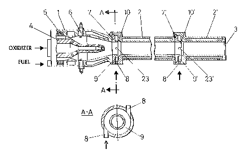
Figure 1. Shows an schematic representation in section of the gun which is the
object of this invention and which also shows a transverse section of one of
the annular
material injectors that is incorporated into the barrel.
Figure 2. Shows a section of the invention's detonation gun's explosion
chamber, indicating the new gas injection system for generating mixtures of
different
composition in various zones of the chamber.
Figure 3. Shows a partial view of a material injector incorporated into the
barrel
corresponding to ax-ariation where the annular injector also incorporates an
auxiliary
product entrance. In addition, it shows a variation of the flange that
incorporates the
said injector to permit the connection of two-barrel segments with different
diameters.
Figure 4. Shows a variation of the view given in Figure 3 where the material
exits present a multiplicitv of orifices that open out to the inside of the
barrel.
Figure 5. Shows a representation of the flange that houses the annular
injector
comprising separator means that allow the distance between the flange and a
segment of
the barrel to be varied, this providing an adjustable separation between the
two parts for
the entrance of outside air.
Figure 6. Shows a variation of the annular injector with a diametrical
reduction-
expansion. It also shows a variation of this injector with longitudinal
grooves.
Figure 7. Shows a variation of the annular injector where the outlet in
communication with the barrel is fitted with a multiplicity of radial orifices
and an axial
feeder ring.
BEST iNIODE FOR CARRYING OUT THE INVENTION
CA 02388618 2008-01-09
27395-120
12
In view of these drawings, one can see how the gun object of the invention
comprises an explosion chamber (1) and a barrel (2) of suitable length, open
at one end
(3) and closed at the other, and wliich is made up of one or more segments
(2), (2'),
joined by flanges (7), (7') that can incorporate entrances for products.
The explosion chamber (1) comprises the fuel injector (5), the oxidizer
injector
(4) and the spark plug (6) for the ignition of the fuel-oxidizer mixture
obtained in the
explosion chamber. In addition, it incorporates the connectors that correspond
to a gun
cooling circuit (not represented), for example, using water.
As can be seen from Figure 2, the explosion chamber (1) comprises in the
rearmost zone, just before the orifices (17) used for oxidizer feed, a
protuberance or
internal perimeter rib (14) that determines a narrowing that defines an
annular volume
(11) into which the fuel is introduced exclusively and which is fed via the
orifices (16)
located in a bushing that is concentric to the explosion chamber, or in the
actual walls
(5) and which open into this chamber at the most rearwards position (11) prior
to the rib
(14).
One of the main characteristics of the gun of the invention refers to the fact
that
it incorporates an oxidizer feeder (4) (for example, oxygen) arranged
concentrically and
internally to the explosion chamber (1), with a prolongation at one end that
extends
practically to the zone that communicates with the gun's barrel (13)
incorporating a
multiplicity of orifices (17), (18) for feeding the oxidizer, for example,
oxygen, which
allows the feeding of this oxidizer to various locations distributed
throughout the
explosion chamber.
Specifically, a first series of oxidizer (for example, oxygen) feeding
orifices (17)
lias been provided in a first location close to the ignition zone (12), where
the
prolongation (15) of the feeder (4) incorporates other oxidizer feeding ducts
(18) along
its length that are employed to progressively enrich the mixture during its
advance
towards the chamber zone that communicates with the barrel (13).
Another important characteristic of the invention refers to the fact that the
gun's
barrel (2) incorporates one or more expansion and distribution annular
chambers (9)
(also shown in Figure 1) with their corresponding
products feeding inlets (8), chambers (9) that open to the
CA 02388618 2008-01-09
27395-120
13
inside of barrel (2) via annular outlets (10) directed towards the barrel's
exit.
The annular chambers (9) are established within the flanges (7), independently
of the barrel (2) and can be fixed to it by any method, so that these flanges
(7), together
with the barrel's segment or segments (2), (2'), can be substituted or
replaced, having
several barrels for a single gun, including various lengths or diameters,
which, in
addition, permits greater ease during maintenance operations of the injection
ducts,
wllich allows the operational features of a single gun to be substantiallv
modified, using
the most suitable contiguration for each case. Figure 1 and 6 represent a
barrel with a
terminal segment (2') of the same diameter as the first section (2), whereas
figure 3 to 5
show a barrel where the terminal segment (2') has a greater diameter than the
first
section (2).
In accordance with another characteristic of the invention, just as can be
seen in
Figure 5, the flange (7) can incorporate a separator device (19) that permits
the
separation between the flange (7) and the initial sector (2) of the barrel to
be modified,
so that an adjustable separation may be established between them to allow the
entry of
outside air.
The feeding duct (8) may be employed for the injection of coating powder, thus
achieving a good distribution of the same and minimizing the volumetric
density of the
powder introduced per unit of area, since instead of entering the barrel at a
single point,
it does so via chambers (9) and annular outlets (10) and consequently in a
more
homoaeneous and distributed form.
The annular feeding duct can also be used for the injection of active,
reactive or
neutral substances, such as, for example, fuel, oxygen air or nitrogen etc, in
this way
modifying the conditions of the actual thernlal spray process itself and
making it
possible to modify the parameters based on the injection of various products
at different
points inside the barrel.
As from this basic structure and in accordance with Figures 3 and 4, it is
possible to incorporate, in the same flange (7), in addition to the already
mentioned
annular chamber (9), a second annular chamber (20), with its corresponding
inlet (21)
and outlet (22) ducts, designed to make up an auxiliary products injector,
which may be
CA 02388618 2008-01-09
27395-120
i4
the same or different to those injected via the main feeding chamber (9) and
therefore,
for example, it would be possible to inject different powders in order to form
coatings
with two or more different materials.
In addition, and as can be perfectly seen in the cited Figures 3 and 4, the
diameter of the barrel segment (2') is greater than that of the first segment
(2), and more
specifically, the second segment (2') diameter coincides with the external or
maximum
diameter of the annular outlet (10') of the chamber exit, also annular (9), at
the same
time being larger than the internal diameter of the first segment (2) of the
said barrel,
with which, as already said and in accordance with the invention's object, the
injection
of a gas via the entrance (8), emerges from the annular outlet (10) forming a
kind of
film. which is also annular and established between the actual barrel wall
itself (2') and
the hot gases produced in the explosion, making contact between them and the
cooled
barrel difficult and consequentlv allowing a reduction in the energy losses.
In Figure 1, the flange (7) allows the connection of the two segments of the
barrel (2, 2') of the same diameter, where it is also possible to make this
connection
with the layout shown in Figure 6, where two sectors (2, 2') of the barrel
with the same
diameter are connected by means of a progressive reduction of diameter in the
terminal
zone of the first section (2) of the barrel, and of a posterior progressive
expansion in
correspondence with the output outlet (10) of the annular chamber (9).
As can be seen in F igure 4, one of the barrel access outlets (22') can be
made,
instead of being a continuous annular slot, through a series of orifices,
arranged
approximately in a ring. Also shown in Figures 1 and 6 is the presence of
longitudinal
slots (23) (also shown in Figure 1) in the outlets (10) with the function of
increasing the
amount of powder that may be processed by the said components. These
configurations
may be used at any of the outlets of any of the material injectors incorpoi-
ated into the gun.
In Figure 7, the outlet (10), in addition to presenting an annular axial
communication with the ba_-rel, includes a multiplicity of orifices (24) along
its length,
which open radially on the inside of the barrel and allow the product feeding
to be
performed in a more distributed manner. This configuration may be used at any
of the
outlets of any of the material injectors incorporated into the gun.
CA 02388618 2002-04-23
The outlets (10) that communicate the annular chambers (9) with the inside of
the barrel (2) are configured as ducts formed by the internal wall of the
barrel and by an
axial rib (25) in the flange (7), which, on the one hand, permits the correct
distribution
of the material inside the barrel and, on the other, regulates the interaction
between the
5 gases produced bv the explosions and the materials supplied in the annular
chambers
(9). The outlets may be configured as annular ducts that are variable in
longitude and
section in combination, or not. with radial ducts of the type represented by
the orifces
(24) and the slots (23).Ultimately, the geometry of the outlet (10) is
determined by the
characteristics of the product injected into the barrel and by the properties
of the coating
10 to be achieved. For example, if the material fed into the barrel is a gas
and it is to be
used to insulate the gases produced in the explosion from the cooled walls of
the barrel,
then the most suitable outlet would have a configuration similar to that
numbered (10)
in Figure 6. On the other hand, for feeding a material in the form of powder,
an outlet
confiauration such as that represented in Figure 7 is more appropriate.