Note: Descriptions are shown in the official language in which they were submitted.
CA 02388625 2002-05-31
Express Mail Label No. ET411309261US
Attorney L>ocket No. 60680-1384
Dana Case 5477 VVSS
SERVICE TOOL FOR REMOVAL OF VALVE SEAL ASSEMBLY
BACKGROUND OF THE INVENTION
Field of Invention
The present invention relates to valve stem seal assemblies for use in
internal
combustion engines, and more particularly to service tools adapted for removal
of
such assemblies from valve guides of engines.
Description of the Prior Art
Those skilled in the art will appreciate the manner in which intake and
exhaust
valves are employed in cylinder heads of internal combustion engines. Such
valves,
1o supported for reciprocal motion within valve guides, include integral
elongated stems
extending away from the engine cylinder heads, the ends of the stems typically
interacting with rotating overhead cams for cyclic or repeated opening and
closure of
the valves against the force of valve return springs during the combustion
cycle.
Obviously, in order to permit unobstructed reciprocal movement of the stem in
the
guide, some mechanical clearance must exist between the valve guide and the
moving
stem. A plurality of valve stems thus move reciprocally to and from the
cylinder
head, each within its individual guide, and so-called valve stem seal
assemblies are
used to seal against leakage of oil through a mechanical clearance path
between each
annular engine valve guide and its associated valve stem.
2o As is well known, the intake port of a combustion chamber is opened and
closed by the reciprocating motion of at least one intake valve, which in turn
is driven
by the rotary motion of a cam, the latter being affixed to and rotatable with
an engine
camshaft. The intake valve permits fuel mixed with air to flow into the
combustion
chamber. In addition, an internal combustion engine has at least one exhaust
valve
and associated exhaust port for releasing expended combustion gases to the
atmosphere. Typically, intake and exhaust valves are of similar construction
and both
include stems integrally affixed to the valves.
~2___
CA 02388625 2002-05-31
Express Mail Label No. ET411309261US
Attorney Docket No. 60680-1384
Dana Case 5477 VVSS
In. the typical engine, a 'valve stem seal assembly is fitted over or atop
each
valve guide, wherein each seal assembly has a typically cylindrical flangeless
retainer
fractionally mounted to an associated valve guide, or is alternately retained
in place by
a flanged retainer and having a normally bottom retainer flange that
cooperates with a
return spring to assure securement of the assembly on the valve guide under
conditions of reciprocal movement of the valve stem within the guide. Each
valve
stem seal assembly normally has two primary parts; 1) an elastameric oil seal
engaging the valve stem to control leakage of oil between valve stem and guide
as
noted, and 2) a cylindrical retainer mounted atop of the valve gi;~ide to hold
the oil seal
in place. One particular design of the flangeless style of retainer includes a
plurality
of elongated fingers to fractionally hold the retainer in place on the guide.
The seal is
supported in the top of the retainer, and retainer fingers depend downwardly
from a
portion of the retainer below the elastomeric body of the seal. F.adially
inwardly
extending ends of the fingers are circumferentially adapted to be retained by
detents
located in the valve guide circumference. Removal of such valve stem seal
assemblies is rather cumbersome without an effective tool.
The service tool of the present invention overcomes normal difficulties of
removal, and thus facilitates replacement of finger retainer-style valve stem
seal
assemblies during an engine overhaul.
SUMMARY OF THE INVENTION
The present invention provides a service tool for dislodgement and removal of
valve stem seal assemblies installed atop valve guides of internal combustion
engines.
The service tool is particularly suited for flangeless retainers having
elongated fingers
cireumferentially arranged for securement to the valve guide, wherein the
guide
includes detents for fractionally retaining inwardly turned ends of the
lungers. In a
preferred form, the service tool includes an exterior cylindrical shell formed
in two
symmetrical halves divided along the longitudinal axis of the shell. A
cylindrical
--3
CA 02388625 2002-05-31
Express Mail Label No. ET411309261US
Attorney Docket No. 60680-1384
L)ana Case 5477 VVSS
puller element is encased within and axially movable in the shell, the puller
element
also comprising two mating symmetrical halves divided along the same axis. The
puller halves are hinged at their top end, and define gear teeth e~;tending
about their
exterior upper surfaces, and radially inwardly turned arms at their lower
ends. The
puller arms comprise cam ends which include upwardly turned surfaces adapted
to
engage and dislodge circumferentially spaced fingers of the valve seal
assemblies
when the tool is circumferentially closed (i.e., via hinge) about ain
installed valve stem
seal. Respective mating halves of pulley and shell are coupled together in a
manner to
support axial vertical movement of the pulley within the shell, and to permit
the
l0 respectively mated halves to swing open together about the top hinge of the
pulley.
A pair of symmetrically opposed worm gears is supported in sockets of the
exterior shell halves; one gear and socket are positioned in each half,
wherein each
worm gear respectively engages gear teeth of one of the pulley halves. A pair
of
levers is disposed for angular up and down movement, wherein each lever is
rigidly
affixed to one respective worm gear, and extends radially outwardly therefrom.
Simultaneous movement of said levers produces an angular follower movement of
the
worm gears within their respective sockets, causing the gear teeth of the worm
gears
to move in rotatably axially directed arcs, whereby the pulley is caused to
move up
within the shell to dislodge the retainer fingers from their valve guide
detents via the
pulley cam ends.
BRIEF DESCRIPTION OF THE DRAWINGS
Figure 1 is a cross-sectional view of one preferred embodiment of the service
tool of the present invention, shown placed over and closed about an installed
valve
stem seal.
Figure 2 is a cross-sectional view of the same pref erred embodiment of the
service tool during first stage of finger removal from detents of a valve
guide.
CA 02388625 2002-05-31
Express Mail Labell No. ET411309261US
Attorney Docket No. 60680-1384
Dana Case 5477 VVSS
Figure 3 is a cross-sectional view of the same preferred embodiment of the
service tool shown in an advanced stage wherein the valve stem seal is being
vertically lifted from the valve guide.
Figure 4 is a top view of the same preferred embodiment of the service tool,
with a superimposed phantom view demonstrating operation of a side-mounted
hinge
employed to open and close the service tool about a valve stem seal.
Figure 5 is an elevation view of and alternate preferred embodiment of the
1o service tool, with a superimposed phantom view for demonstrating operation
of a top
mounted hinge mechanism.
Figures 6 and 7 are perspective and top views, respectively, of the alternate
preferred embodiment of Figure S.
IS
Figure 8 is a cross-sectional view of a dovetailed connection between the
service tool parts indicated.
DETAILED DESCRIPTION OF PREFERRED EMBODIMENTS
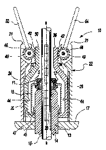
2o Referring initially to Figures 1-3, a preferred embodiment of the service
tool
is positioned in place to remove a valve stem seal 12, shown installed atop of
an
annular valve guide 14. The valve stem seal 12 is of the type supported in
place by a
flangeless cylindrical retainer 16 having longitudinally extending elongate
retainer
fingers (also shown at 16). The fingers 16 comprise radially in'vardly turned
ends 20
25 that cooperate with integral horizontally disposed detents 18 (Fi.gure 2)
of the valve
guide 14 for securing the valve stem seal 12 in place. Those skilled in the
art will
appreciate that the valve stem seal 12 is resilient, typically formed of
elastomeric
material, to sealingly engage an elongate valve stem 15.
5
CA 02388625 2002-05-31
Express Mail Label No. ET411309261US
Attorney Docket No. 60680-1384
Dana Case 5477 WSS
The valve stem 15 is supported for reciprocal movement within the valve
guide 14, which fixedly extends longitudinally (or upwardly, as shown) through
an
aperture 13 of a cylinder head deck 17. The annular body of the seal 12 is
adapted to
engage the circumferential exterior surface of the valve stem 15 :for limiting
and or
otherwise controlling leakage of crankcase oil along a path between the stem
15 and
the valve guide 14 for undesirable admission of oil into the combustion
chamber, as
will be appreciated by those skilled in the art. The seal 12 is supported
within an end
wall 11 of the fingered retainer 16, the retainer being formed of metal in the
preferred
embodiment described and shown herein. To enhance sealing effectiveness, a
garter
to spring 5 encircles the exterior of the seal 12 to impart a radial
compression force
against the reciprocally moving valve stem 15.
The service tool 10 comprises an exterior shell 22 having. a first and second
ends 21 and 23, respectively (Figure 2). The exterior shell consists of two
shell
halves 24 and 26, which are divided symmetrically along an axis a-a.
A pulley element 30 is symmetrically encased within the exterior shell 22, and
is axially movable therein. Both exterior shell and pulley structures have
fiwstoconical
upper body portions in the preferred embodiment, as shown. This design permits
the
seal dislodgement mechanism to be situated above the body of the seal to be
removed,
as will be appreciated by those skilled in the art. The pulley element 30
includes
2o halves 32 and 34 that are also divided along axis a-a. The pulley element
30 has a top
end 36 and a bottom end 38 which are substantially coterminous with the first
or top
end 21 and second or bottom end 23 of the exterior shell 22.
It will be appreciated by those skilled in the art that the pulley element 30
is
coupled to, and yet relatively movable along axis a-a with respect to the
exterior shell
22. For this purpose each of the pulley halves 32 and 34 must be dovetailed or
keyed
(see Figure 8) to their respective mated exterior shell halves 24 and 26.
-.6 -
CA 02388625 2002-05-31
Express Mail Label No. ET411309261US
Attorney pocket No. 60680-1384
L)ana Case 5477 VVSS
Referring to Figure 4, the halves 24 and 26 are adapted to swing open about a
slide-mounted hinge 28 that is parallel to axis a-a. Since they are coupled to
the
halves 24 and 26, the respective mated pulley halves 32 and 34 will also swing
open
with the exterior shell halves.
In other applications, depending on particular geometries of the associated
engine, the hinged structure may alternatively be top-mounted as shown in the
alternative embodiment shown in Figures 5, 6, and 7. In the latter embodiment,
the
pulley element halves 32 and 34 are connected at their first or top end 36 by
a pair of
hinges 28' . Thus, the lower ends 23 of the shell halves 24 and 26 swing apart
along
an arc A-A about the top-mounted hinges 28' {Figure 5), in order to
accommodate
placement over the valve stem seal to be removed. Obviously, the respectively
mated
pulley halves 32 and 34, coupled to the shell halves 24 and 26, will swing
open along
arc A-A as well.
Referring particularly to Figures 3 and 5, a set of gear teeth 40 and 42 are
provided in the exterior surfaces of the upper ends of the pulley halves 32
and 34,
respectively. The cireumferential body collectively presented by the pulley
element
halves 32 and 34 has a cross-section defining arms 44 at the bottom of the
pulley
element 30. The arms 44 incorporate cam ends 45 which contain upwardly turned
cam surfaces 47 (Figure 1) for engaging the inwardly turned ends 20 of the
retainer
fingers 16 in a manner to be described.
The teeth 49 of each of the pair of worm gears 48 (Figure 1) are disposed in
spherical reaction sockets 50 (Figure 2) situated in each exterior shell half
24 and 26.
Each worm gear 48 engages respective gear teeth 40 and 42 (Figures 3 and 5) of
the
pulley element halves 32 and 34. A pair of levers 52 and 54 is rigidly affixed
to
respective worm gears 48, each lever to one gear. The levers are spaced
circumferentially 180 degrees apart about the upper circumference of the tool.
Thus it
will be appreciated that simultaneous downward movement of the levers will
give rise
to an angular movement of the wornz gears within their respective sockets,
causing the
- 7-
CA 02388625 2002-05-31
Express Mail Label No. ET411309261US
Attorney Docket No. 60680-1384
>r~ana Case 5477 VVSS
teeth of the worm gears to rotate in axially directed arcs. This action will
cause an
upward movement of the puller element 30, wherein the ends 20 of the fingers
16 may
be effectively dislodged from the detents 18 by the interaction oir the cam
ends 45
with the ends 20.
The sequence of dislodgement and removal of a valve stem seal 12 may now
be described with particular reference to Figures 1-3 as follows. In Figure l,
as
earlier noted, the service tool 10 is shown placed over a valve stem seal 12
for
removal of the seal, the shell halves 24 and 26 being closed together for this
purpose.
In Figure 2, it will be apparent that the upwardly turned cam surfaces 47 of
the cam
1o ends 45 have effectively dislodged the radially inwardly turned ands 20 of
the retainer
fingers 16, as shown. Thus, as the levers 52 and 54 are displaced downwardly,
the
cam ends 45 will cause the retainer ends 20 to be flared radially outwardly
for
dislodgement of the retainer ends 20 from the detents 18. In Figure 3, it will
be
apparent that the levers 52 and 54 have been yet further downwardly displaced
to
cause actual elevation of the puller element halves 30 in 32, in turn
physically lifting
the seal 12 from the valve guide.
Although the described embodiment of this invention contemplate that the
exterior shell 22, worm gears 48, and the puller element 30 are each formed of
metal,
other materials may be suitable, depending upon strength of materials and
desired
2o useful lives of the service tool 10. For example, some glass-filled nylons
or other
plastics may be suitable in some applications. Obviously, in such cases, to
the extent
that the worm gears interface with both shell and puller elements, all parts
should
preferably be formed of either plastic materials or o.f metal materials, one
or the other,
and not in a combination of materials.
Finally, it will be noted that the second, Lower, end 23 of'the exterior shell
22
acts as a base of the tool 10, supported on the cylinder head deck 17, during
removal
operation. Thus, the lever reaction load during seal dislodgement and removal
is
transferred into the base and the deck 17.
._ g__
CA 02388625 2002-05-31
Express Mail Labei~ No. ET411309261US
Attorney Docket No. 60680-1384
Dana Case 5477 WSS
The above description is intended to be illustrative, and not limiting. Many
embodiments will be apparent to those of skill in the art upon reading the
above
description. The scope of the inventiozl should be determined, however, not
with
reference to the above description, but with reference to the appended claims
and the
full scope of equivalents to which the claims are entitled by law.
g__._