Note: Descriptions are shown in the official language in which they were submitted.
CA 02389267 2002-05-08
WO 01/34361 PCT/US00/30490
A METHOD FOR CONTINUOUSLY PRODUCING EXPANDED
THERMOFORMABLE MATERIALS
BACKGROUND OF THE INVENTION
1. Field of the Invention
The present invention relates to a method of producing expanded
thermoformable materials and, more particularly, to an energy efficient
method for continuously producing expanded thermoformable materials.
2. Description of the Prior Art
Processes used to make expanded thermoformable materials
typically involve placing a thermoformable polymeric material blank
between mold plates, which are attached to a heated press. The
thermoformable polymeric material blank is heated to a temperature at
which the thermoformable material will adhesively bond with the mold
plates by hot tack adhesion. The mold plates are than separated apart with
the thermoformable material still adhered to the mold plates so as to effect
an expansion of the cross-section of the thermoformable material.
Typically, the surfaces of the mold plates that are bonded to the
thermoplastic material blank have a plurality of perforations thereon. The
thermoplastic material will adhesively bond to the non-perforated portion of
this surface so that when the mold plates are separated apart a plurality of
cells will be formed within the cross-section of the expanded
thermoformable material. Generally, these perforations can have a variety
of different geometries and can be arranged in an array of patterns on the
surface of the mold plates, thereby creating thermoformable materials
having a variety of cross-sectional geometries. Such methods for
expanding thermoformable materials are set forth in U.S. Patent No.
4,113,909 (Beasley), issued September 12, 1978, U.S. Patent No.
CA 02389267 2002-05-08
WO 01/34361 PCT/US00/30490
2
4,164,389 (Beasley), issued August 14, 1979, U.S. Patent No. 4,315,051
(Rourke), issued February 9, 1982, U.S. Patent No. 4,269,586 (Ronayne),
issued May 26, 1981, U.S. Patent No. 4,264,293 (Rourke), issued April 28,
1981, and U.S. Patent No. 4,315,050 (Rourke), issued February 9, 1982,
each of which is incorporated herein by reference.
The problem with these processes is that the manufacturing
personnel must wait approximately fifteen to twenty minutes until the
expanded thermoformable material has cooled off before they can remove
it from the press and insert a new thermoformable blank. Thus, the cost of
production is increased because the manufacturing personnel must wait
long periods of time before each new thermoformable material blank can
be inserted into the press.
Another disadvantage is that if expanded thermoformable materials
with different cross-sectional geometries is desired, than the mold plates
must be replaced in the press to produce the desired product. This causes
several problems. First, the manufacturing personnel must wait for the
previous expanded thermoformable material product to cool off so that it
can be removed. Second, they must also wait for the entire press to cool
off so that it reaches a safe temperature before the manufacturing
personnel can again work with the press. The mold plates can be heated
to temperatures in excess of 300°C, which creates dangerous conditions
if
the manufacturing personnel are not cautious. If they attempt to remove
the mold plates before they are completely cooled off, grave injuries or
even death could occur. Thus, the cost of production is increased if a
variety of expanded thermoformable materials are desired because of the
additional time and precautions which the manufacturing personnel must
take when replacing the mold plates.
Another disadvantage is that the thermoplastic material is heated
and cooled in the same zone. Each thermoformable material sheet that is
to be expanded must be heated in the press from room temperature to the
CA 02389267 2002-05-08
WO 01/34361 PCT/US00/30490
3
temperature at which the material will exhibit hot tack adhesion. Thus,
additional time is required because the thermoplastic material sheet is not
pre-heated prior to its insertion into the press.
In addition, the cost of production is substantially increased because
of the amount of wasted energy in these conventional processes. Each
thermoformable material must be reheated using new energy due to the
fact that the press must be cooled to near room temperature prior to
removal of expanded thermoformable material and insertion of a new sheet
of thermoformable material. Thus, the cost of production is increased
because new energy must be purchased to heat each new sheet of
thermoformable material that is to be expanded and all of such energy is
wasted during the cooling process.
Furthermore, another disadvantage is that the processes described
above are neither automated nor continuous, and typically require multiple
manufacturing personnel to produce one expanded thermoformable
product. Obviously, the use of multiple personnel greatly increases the
cost of manufacturing, together with the long product cycle times and
energy loss.
Accordingly, there is a need for an improved method of continuously
producing expanded thermoformable materials that avoids the
aforementioned disadvantages. In this regard, the present inventor has
developed a unique continuous process, which substantially reduces
product cycle time, labor costs and energy consumption. That is, only one
member of the manufacturing team is required for loading and unloading of
the thermoplastic material.
SUMMARY OF THE INVENTION
The present invention provides an energy efficient method for
continuously producing expanded thermoformable materials. This method
CA 02389267 2002-05-08
WO 01/34361 4 PCT/US00/30490
comprises the steps of: conveying a thermoformable assembly having a
thermoformable material disposed between a pair of mold or caul plates
through at least one heating zone; expanding the heated thermoformable
material in a press zone; and cooling the expanded thermoformable
material in at least one cooling zone. Optionally, the cooled expanded
thermoformable material is returned to the thermoformable material sheet
loading station, wherein the expanded thermoformable material is removed
from the mold plates and a new thermoformable material sheet is disposed
therebetween for subsequent treatment in the continuous system.
Specifically, the thermoformable assembly is heated to a
temperature at which the thermoformable material adhesively bonds to
each mold plate. Thereafter, the thermoformable assembly is disposed
between a pair of press plates, whereby the press plates engage the mold
plates of the thermoformable assembly. The thermoformable material
sheet which is disposed between the mold plates is then heated to a
temperature in the range between about 50°C to 300°C, preferably
between 100°C to 250°C, and the press plates are thereafter
slowly
separated so as to effect an expansion of the cross-section of the
thermoformable material to the desired width. The surface of the mold
plates which comes into contact with the thermoformable material may
have perforations thereon, thereby creating cells in the cross-section of the
expanded thermoformable material during the expansion process.
Alternatively, each set of mold plates may have either the same or different
diameter perforations thus enabling the creation of expanded
thermoformable material having different or the same cell cross-sections.
The thermoformable assembly, which has been expanded, is then
removed from the press zone and conveyed through at least one cooling
zone, wherein the expanded thermoformable material is cooled to a
temperature sufficient for maintaining its structural integrity.
CA 02389267 2002-05-08
WO 01/34361 5 PCT/US00/30490
In one embodiment of the present invention, the heating, press, and
cooling zones are enclosed within a housing capable of capturing heat from
each individual heating, press and cooling zone, and recycling it so that
heat applied to prior thermoformable assemblies can be reused to heat a
subsequent thermoformable assembly, thereby conserving energy by
recycling heat during operation of the continuous process. The housing
captures heat and recycles it using ducts. Ducts are routed from the
cooling zones that follow the press station to the heating zones, wherein
heat emitted from the thermoformable assembly in the cooling zone is
transferred to the heating zones and applied to subsequent thermoformable
assemblies.
The present invention is continuous, i.e., a conveyorized mechanism
is used to move a plurality of thermoformable assemblies through various
heating, press (i.e., expansion) and cooling zones, whereby an expanded
thermoformable material is produced about every 1-2 minutes.
Other and further objects, advantages and features of the present
invention will be understood by reference to the following specification in
conjunction with the annexed drawings, wherein like parts have been given
like numbers.
BRIEF DESCRIPTION OF THE DRAWING
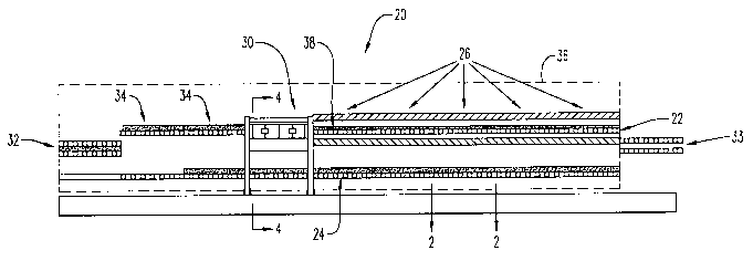
FIG. 1 is a schematic view of the system for continuously producing
expanded thermoformable materials according to the present invention;
FIG. 2 is a side cross-sectional view along line 2-2 of FIG. 1
depicting a single thermoformable assembly traversing through a heating
zone prior to expansion which is disposed on top of the finished product
return conveyor;
FIG. 3 is a front cross-sectional view of FIG. 2;
CA 02389267 2002-05-08
WO 01/34361 6 PCT/US00/30490
FIG. 4 is a cross-sectional view along line 4-4 of Fig. 1 depicting the
press zone without any thermoformable assembly disposed between the
press plates;
FIG. 5 is a cross-sectional view along line 4-4 of Fig. 1 depicting the
press zone with a thermoformable assembly disposed between the press
plates after the press plates have been retracted to form an expanded
thermoformable material;
FIG. 6 is a schematic representation of a thermoformable material
sheet disposed between a pair of mold plates;
FIG. 7 is a schematic representation of the thermoformable material
sheet disposed between a pair of mold plates which have been partially
retracted by associated press plates (not shown);
FIG. 8 is a schematic representation of the thermoformable material
sheet disposed between a pair of mold plates which have been fully
retracted to produce an expanded thermoformable material;
FIG. 9 illustrates a top plan view of the perforated surface of a mold
plate;
FIG. 10 is a cross-sectional view along line 10-10 of Fig. 9;
FIG. 11 illustrates, in a perspective view, a pair of oppositely
disposed mold plates demonstrating the non-alignment between the
perforations from one mold plate with those of another which provides for
the formation of the unique honeycomb structure of the expanded
thermoformable material of the present invention; and
CA 02389267 2002-05-08
WO 01/34361 PCT/US00/30490
7
FIGS. 12-15 show different expanded thermoformable materials,
which may be made using the method of the present invention.
DESCRIPTION OF THE INVENTION
The present invention can best be described by reference to the
attached figures, wherein FIGS. 1 through 5 depict the energy efficient
continuous system 20 which is capable of producing expanded
thermoformable material. System 20 preferably comprises a first conveyor
means 22, a second conveyor means 24 enclosed within housing 36. First
conveyor means 22 includes a plurality of heating zones 26, a heatable
press zone 30, and a plurality of product cooling zones 34. A
thermoformable assembly 38 comprising a first mold plate 40, a second
mold plate 42, and a thermoformable material sheet 48 disposed
therebetween is placed on a first conveyor means 22 for conveying through
heating zones 26. Preferably, first mold plate 40 and second mold plate 42
are made of aluminum and are 3 to 4 millimeters in width.
As thermoformable assembly 38 is conveyed through heating zones
26, thermoformable material sheet 48 is heated to a temperature at which
thermoformable material sheet 48 will adhesively bond to the surfaces of
first mold plate 40 and second mold plate 42 by hot tack adhesion.
Press zone 30 includes an upper press plate 44 and a lower press
plate 46. Thermoformable assembly 38 is conveyed into press zone 30
where it is disposed between upper press plate 44 and lower press plate
46. Thermoformable assembly 38 is secured to upper press plate 44, via
connectors 45, which slidably engage upper mold plate 40 to upper press
plate 44. Similarly, lower mold plate 42 is simultaneously engaged with
lower pressure plate 46. Upper press plate 44 and lower press plate 46 are
heated via electric elements disposed within each press plate (not shown),
whereby thermoformable material 48 is heated conductively through upper
press plate 44 and lower press plate 46 to a temperature in the range
CA 02389267 2002-05-08
WO 01/34361 PCT/US00/30490
8
between about 50° and 300°C, preferably between 100° and
250°C.
Thereafter, upper press plate 44 and lower press plate 46 are separated so
as to effect an expansion of the cross-section of thermoformable material
48.
FIGS. 6 through 8 show a sequence of schematic representations
depicting the expansion of the cross-section of thermoformable material 38
while in press zone 30. FIG. 6 shows thermoformable assembly 38 when it
enters press zone 30, whereby thermoformable assembly 38 is disposed
between upper press plate 44 and lower press plate 46. FIG. 7 shows
upper press plate 44 and lower press plate 46 as they begin to separate
from each other and expand thermoformable material 48 which is adhered
to the adjacent surfaces of first mold plate 40 and second mold plate 42,
respectively. FIG. 8 depicts the fully expanded thermoformable material 50
after the expansion step but before expanded thermoformable material 50
is removed from press zone 30.
A significant feature of the present invention is the construction of
thermoformable assembly 38. First mold plate 40 and second mold plate
42 are disposed about opposite surfaces of thermoformable material 48
prior to the placement of thermoformable assembly 38 onto first conveyor
means 22. First mold plate 40 and second mold plate 42 remain loosely
connected to thermoformable material 48 until it is raised to a temperature
at which it will exhibit hot tack adhesion. Thereafter, first mold plate 40
and
second mold plate 42 are adhesively bonded to thermoformable material
48 and remain bonded throughout the entire process, until thermoformable
assembly 38 is cooled to a temperature in the range between about 10°
to
30°C. When expanded thermoformable material 49 is cooled to a
temperature within this range it easily releases from first mold plate 40 and
second mold plate 42. This novel process substantially increases the rate
of production of expanded thermoformable materials by allowing
consecutive thermoformable assemblies 38 to be placed on first conveyor
means 22. Each thermoformable material sheet 48 is disposed between its
CA 02389267 2002-05-08
WO 01/34361 9 PCT/US00/30490
own pair of mold plates, i.e., first mold plate 40 and second mold plate 42.
This eliminates the need for waiting for expanded thermoformable
assembly 38 to cool before removing it from the press zone 30. Energy
efficient method of the present invention allows each expanded
thermoformable material 49 to be rapidly removed after the pressing
process, thereby allowing the next consecutive thermoformable material 50
to be inserted into the press zone 30 without waiting for a cooling period.
Thus, the energy efficient process according to the present invention can
produce an expanded thermoformable material 50 about every 1-2 minutes
versus the old batch method, which produced approximately one expanded
thermoformable material in about 15-20 minutes.
Optionally, first mold plate 40 includes a perforated surface 52 and
second mold plate 42 includes a perforated surface 54 which is disposed
opposite to perforated surface 52. FIGS. 9 through 11 show perforated
surface 52 and perforated surface 54 with a plurality of perforations 56
thereon. Perforated surface 52 and perforated surface 54 are disposed
opposite to one another and have thermoformable material 48 disposed
therebetween, whereby perforated surface 52 and perforated surface 54
are in contact with opposite sides of thermoformable material 48.
During the heating and expansion steps, thermoformable material 48
adheres to the non-perforated portion 57 of perforated surface 52 and
perforated surface 54, by hot tack adhesion. When upper press plate 44
and lower press plate 46 are separated or retracted in press zone 30, a
plurality of cells 58 are formed in the expanded thermoformable material
50, as depicted in FIGS. 12-15, wherever perforations 56 are disposed on
perforated surface 52 and 54. In addition, a plurality of ribs 60 are formed
in the expanded thermoformable material 48 at the non-perforated portion
57 of first perforated surface 52 and second perforated surface 54 of first
mold plate 40 and second mold plate 42, respectively.
CA 02389267 2002-05-08
WO 01/34361 PCT/US00/30490
During the expansion process, cells 58 can be vented through first
mold plate 40 and second mold plate 42 so that pressure within cells 58 will
be in equilibrium with the pressure without the ribs 60 of the
thermoformable material 48, thereby preserving the pattern and integrity of
5 the cells 58 within the cross-section of the expanded thermoformable
assembly 38.
Another significant feature of the present invention is that
perforations 56 on first perforated surface 52 and second perforated
10 surface 54 may be arranged in different configurations for each consecutive
thermoformable assembly 50. In addition, first perforated surface 52 and
second perforated surface 54 can be aligned in different patterns, such that
perforations 56 on first perforated surface 52 can overlap perforations 56
on second perforated surface 54. Thus, producing expanded
thermoformable material 50 with a different array of cells 58 and ribs 60 on
opposite sides of thermoformable material sheet 48.
Another significant feature is that perforations 56 may have many
different geometries, such as arcuate or straight sides. Thus, the present
invention can continuously produce expanded thermoformable material 50
of varied cross-sectional wall geometries without having to shut down for
recalibration.
FIGS. 12 through 15 show several expanded thermoformable
materials 50 with cells 58 and ribs 60. FIG. 12 shows a cross-section view
of expanded thermoformable material 49 formed according to the present
invention, and FIG. 13 shows a front top view of the expanded
thermoformable assembly 50 which has its top layer removed to clearly
depict cells 58 and ribs 60. Perforations 56 of first mold plate 40 and
second mold plate 42, which made cells 58 and ribs 60 of FIGS. 12 and 13,
were diamond shaped.
CA 02389267 2002-05-08
WO 01/34361 PCT/US00/30490
11
FIGS. 14 and 15 show cross-sectional views of another type of
thermoformable assembly 38 comprising a first thermoformable material
layer 64, second thermoformable material layer 68, and an expanded
thermoformable material layer 66 which is disposed between layers 64 and
68.
Referring again to FIGS. 1 through 5, expanded thermoformable
assembly 48 is removed from press zone 30 and conveyed through cooling
zones 34, whereby expanded thermoformable material 49 is cooled to
room temperature . Elevator 32 lowers expanded thermoformable
assembly 50 from first conveyor means 22 to second conveyor means 24.
Second conveyor means 24 conveys and cools expanded thermoformable
assembly 50 to a second elevator 33, whereby expanded thermoformable
assembly 50 is elevated to a removal dock where manufacturing personnel
can remove it.
Housing 36 encloses all the components of energy efficient system
20. Thermoformable assembly 38 is placed on first conveyor means 22 at
one end of housing 36 and expanded thermoformable assembly 50 exits
out the same end by means of second elevator 33. The entire process
according to the present invention is automated, thereby allowing
manufacturing personnel to consecutively place thermoformable
assemblies 38 onto first conveyor means 22 and thereafter wait for the final
product, expanded thermoformable assembly 50, to exit out by second
elevator 33.
During the heating process, housing 36 prevents heat from escaping
by convection out of each heating zone 26. Heat applied to one
thermoformable material assembly 38 in heating zones 26 will be recycled
and used again for the next consecutive thermoformable material assembly
38. In addition, housing 36 captures heat emitted from expanded
thermoformable assembly 50 in cooling zones 34 and transfers it to heating
zones 26 by means of ducts (not shown), wherein the captured heat is
applied to subsequent thermoformabfe material assemblies 38. Thus, the
CA 02389267 2002-05-08
WO 01/34361 PCT/US00/30490
12
energy efficient system 20 reduces energy needs by about 80% versus
conventional methods.
While I have shown and described several embodiments in
accordance with my invention, it is to be clearly understood that the same
are susceptible to numerous changes apparent to one skilled in the art.
Therefore, I do not wish to be limited to the details shown and described
but intend to show all changes and modifications which come within the
scope of the appended claims.