Language selection

Search

Patent 2389331 Summary

Third-party information liability

Some of the information on this Web page has been provided by external sources. The Government of Canada is not responsible for the accuracy, reliability or currency of the information supplied by external sources. Users wishing to rely upon this information should consult directly with the source of the information. Content provided by external sources is not subject to official languages, privacy and accessibility requirements.

Claims and Abstract availability

Any discrepancies in the text and image of the Claims and Abstract are due to differing posting times. Text of the Claims and Abstract are posted:

  • At the time the application is open to public inspection;
  • At the time of issue of the patent (grant).
(12) Patent: (11) CA 2389331
(54) English Title: METHOD AND DEVICE FOR MOVING SUBSEA ROCKS AND SEDIMENTS
(54) French Title: PROCECE ET DISPOSITIF PERMETTANT LE DEPLACEMENT SOUS-MARIN DE PIERRES ET DE MATIERES SOLIDES
Status: Deemed expired
Bibliographic Data
(51) International Patent Classification (IPC):
  • B63C 11/52 (2006.01)
  • E02B 3/02 (2006.01)
  • E02F 3/92 (2006.01)
  • E02F 5/28 (2006.01)
(72) Inventors :
  • FAGERVOLD, TERJE (Norway)
  • FAGERVOLD, GUNNAR (Norway)
  • KVALVAG, GUSTAV (Norway)
  • JACOBSEN, TOM (Norway)
(73) Owners :
  • FOSSURA AS (Norway)
(71) Applicants :
  • GTO SUBSEA AS (Norway)
(74) Agent: ROBIC
(74) Associate agent:
(45) Issued: 2007-01-09
(86) PCT Filing Date: 2000-10-30
(87) Open to Public Inspection: 2001-05-10
Examination requested: 2002-12-13
Availability of licence: N/A
(25) Language of filing: English

Patent Cooperation Treaty (PCT): Yes
(86) PCT Filing Number: PCT/NO2000/000359
(87) International Publication Number: WO2001/032503
(85) National Entry: 2002-04-30

(30) Application Priority Data:
Application No. Country/Territory Date
19995362 Norway 1999-11-03

Abstracts

English Abstract


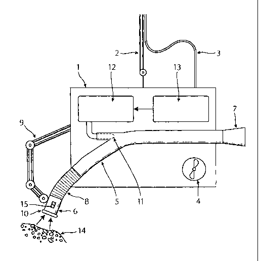
Method for moving subsea
rocks and sediments, also at significant
depths, e.g. in connection with removal of
protective rocks around subsea installations
where maintenance is to be conducted, by
which equipment comprising a tubing with
an ejector nozzle is arranged completely
externally in relation to the tubing on a
standard, remote controlled submarine
(ROV). The ejector nozzle is connected to
a preferably hydraulic powered water pump;
the water pump is run by means of the
energy supply to the ROV, so that the ejector
nozzle produces a pressure gradient through
said tubing. The inlet end of said tubing
is contacted with rocks and sediments to
be moved with the result that said rocks
and sediments are sucked into the tubing
at its inlet end and blown out of its outlet
end. The invention also relates to a device
to conduct the method, which device is
arranged on an ROV and comprises a tubing
(5) through which the sediments (14) are
transported, an ejector nozzle (11) arranged
externally in relation to the tubing (5), and a
water pump (12,13) connected to the ejector
nozzle. All energy is supplied through the
cable(s) (3) to the surface which constitutes
the ROV's ordinary energy supply.


French Abstract

L'invention concerne un procédé permettant de déplacer des pierres et des sédiments sous-marins, à de grandes profondeurs également, ce procédé concernant principalement le déplacement de pierres de protection autour d'installations sous-marines devant subir un entretien. Ce procédé consiste à utiliser un équipement comprenant un tuyau muni d'un éjecteur monté intégralement sur la surface externe d'un robot sous-marin (ROV) classique. L'éjecteur est connecté de préférence à une pompe à eau à commande hydraulique, la pompe à eau étant actionnée par l'énergie utilisée par le sous-marin électrique, de façon que la tuyère d'éjecteur produise un gradient de pression à travers ledit tuyau. L'entrée dudit tuyau est mise en contact avec les pierres et les sédiments devant être déplacés, ces pierres et sédiments étant ainsi aspirés dans le tuyau par son entrée et évacués par sa sortie. L'invention concerne également un dispositif permettant de mettre en oeuvre ce procédé. Ce dispositif est conçu sur un robot sous-marin (ROV) et comprend un tuyau (5) à travers lequel les sédiments (14) sont transportés, un éjecteur (11) disposé extérieurement et relié au tuyau (5), et une pompe à eau (12, 13) connectée à l'éjecteur. Toute l'énergie est acheminée par le(s) câble(s) (3) à la surface constituant l'alimentation ordinaire du robot sous-marin (ROV).

Claims

Note: Claims are shown in the official language in which they were submitted.


5

WHAT IS CLAIMED IS:

1. Device for moving subsea rocks and sediments, including at
significant depths, in connection with removal of protective rocks around
subsea
installations where maintenance is to be conducted, comprising a tubing (5)
through which the rocks and sediments (14) are transported with the aid of a
pressure gradient applied with an ejector nozzle (11) connected to a water
pump
while an inlet end of said tubing is contacted with rocks and sediments to be
moved, characterized in that said tubing, ejector nozzle and water pump are
arranged on a standard, remote controlled submarine and that said ejector
nozzle is arranged completely externally in relation to the tubing (5).

2. Device according to claim 1, characterized in that all required
energy is supplied through at least one cable (3) from the surface to the
remove
controlled submarine.

3. Device according to claim 1, characterized in that the inlet end of
the tubing (5) is movable by means attachable to the remote controlled
submarine.

4. Device according to claim 1, characterized in that the inlet mouth
piece (6) of the tubing (5) is arranged with a rounded edge (10) in order to
reduce inlet loss.

5. Device according to claim 1, characterized in that the tubing (5)
comprises an outlet end (7) shaped as a diffusor in order to reduce outlet
loss.

6. Device according to claim 1, characterized in that the cross-section
of the tubing (5) is substantially even from the inlet moth piece (6) to the
outlet
end (7) and that bends on the tubing are shaped and sized to avoid rocks from
getting stuck in the tubing.


6

7. Device according to claim 1, characterized in that the inlet mouth
piece (6) is furnished with a backflush nozzle for flushing out rocks that
tend to
get stuck in the mouth piece, or to loosen clogged sediment.

8. Device according to claim 1, characterized in that downstream of
the inlet mouth piece (6) an aperture (15), is arranged, through which the
water
will flow, thereby controlling the suction force in the mouth piece and
reducing
the tendency of the mouth piece to get stuck in fine sediment.

9. Device according to claim 1, characterized in that the device is
substantially made from plastic materials with a density close to the density
of
water, so that the device may easily be supported by the remote controlled
submarine.

10. Device according to claim 8, characterized in that the aperture (15)
is an aperture with adjustable size.

11. Device according to any one of claims 1 to 9, characterized in that
the water pump is an hydraulic powered water pump.


Description

Note: Descriptions are shown in the official language in which they were submitted.


CA 02389331 2005-11-18
1
METHOD AND DEVICE FOR MOVING SUBSEA ROCKS AND SEDIMENTS
The present invention relates to a method for moving subsea rocks and
sediments. The invention further relates to a device for performing such a
method.
Background
For work at subsea oil and gas installations or in connection with such
installations,
e.g. maintenance work, there is often a need to move rocks and particulate
material that
partly covers the body that is to be repaired. The body can be a pipeline,
valve housing
and the like.
In a similar way it may arise a need to remove sediments in connection with
new
installations on the sea bottom, or for removal of accumulated drill cuttings
at platforms
or the like.
Similar needs may also occur in connection with subsea work, such as at
harbour
works or barrage or quay structures.
Previously known technology
The most common way to remove sediments in connection with subsea work, is to
utilize large "fans", large and heavy suction devices with a high power
consumption and
specially designed excavators. Disadvantages are that they require a lot of
power and/ or
other resources, they require large surface vessels, have a limited
versatility, are as good
as stationary, or they are not at all suited for deep waters.
NO patent No. 302.043 describes a dredge designed for subsea operations,
especially
to remove or move drill cuttings. The dredge comprises a motor, a pump device
and an
ejector. The motor is designed to run the pump which in its turn provides a
stream of
water to the ejector. The ejector is positioned in a tubing through which the
cuttin;s or
the like are supposed to be transported. The apparatus is designed to rest on
the sea
bottom and to receive energy from the surface, while the inlet end of the
tubing is
intended to be moveable e.g. with the aid of a remote controlled mini
submarine; a so
called ROV.
This apparatus is not suited to move sediments with relatively large rocks,
mainly
because the pipeline has an effective loss of diameter due to the ejector's
design and
position. Furthermore it has geographically a very limited work range, as it
is designed

CA 02389331 2005-11-18
2
to rest at the sea bottom, even though the pipeline is supposed to be somewhat
moveable.
Japanese patent applications Nos. 043 25 799 A and 043 25 800 A describes an
ejector pump system where the ejector is positioned mainly outside the
pipeline so that
the ejector does not reduce the effective diameter of the pipeline. From the
abstract of
these patent applications it is not possible to see what kind of utilizations
these systems
are intended for. Neither are there any indications of dimensions or power
requirements
for these systems.
~b.lectives
It is an object of the present invention to provide a method for
transportation of rocks
and sediments under water, especially in deep waters.
It is a particular object to provide a method for transportation of rocks with
a typical
maximum diameter of about 200 mm.
It is further an object to provide an apparatus for performing said method,
which
apparatus should be versatile in its use, especially in the way that it should
be easy to
move around down at the sea bottom.
It is still further an object to provide such an apparatus which is easy to
control, and
which does not require large amounts of energy to be supplied from the
surface, but
which can utilize the standard power supply available on an ROV.
The invention
These and other objects are preferably achieved through a method for
moving subsea rocks and sediments, also at significant depths, e.g. in
connection with removal of protective rocks around subsea installations where
maintenance is to be conducted, by establishing a pressure gradient through a
tubing by means of an ejector nozzle connected to a preferably hydraulic
powered water pump while an inlet end of said tubing is contacted with rocks
and sediments to be moved, characterized in that said tubing, ejector nozzle
and
water pump are arranged on a standard, remote controlled submarine (ROV)
and that said ejector nozzle is arranged completely externally in relation to
the
tubing.

CA 02389331 2005-11-18
2a
Preferably, the water pump is supplied with energy by the energy supply of
said ROV.
The above mentioned object are also achieved through a device for moving
subsea rocks and sediments, including at significant depths, in connection
with
removal of protective rocks around subsea installations where maintenance is
to
be conducted, comprising a tubing through which the rocks and sediments are
transported with the aid of a pressure gradient applied with an ejector nozzle
connected to a water pump while an inlet end of said tubing is contacted with
rocks and sediments to be moved, characterized in that said tubing, ejector
nozzle and water pump are arranged on a standard, remote controlled
submarine and that said ejector nozzle is arranged completely externally in
relation to the tubing.
Preferably, all required energy is supplied through at least one cable from
the surface to the remove controlled submarine.
Preferably also, the inlet end of the tubing is movable by means attachable
to the remote controlled submarine.
Preferably also, an inlet mouth piece of the tubing is arranged with a
rounded edge in order to reduce inlet loss.
Preferably also, the tubing comprises an outlet end shaped as a diffusor in
order to reduce outlet loss.
Preferably also, the cross-section of the tubing is substantially even from
the inlet moth piece to the outlet end and bends on the tubing are shaped and
sized to avoid rocks from getting stuck in the tubing.
Preferably also, the inlet mouth piece is furnished with a backflush nozzle
for flushing out rocks that tend to get stuck in the mouth piece, or to loosen
clogged sediment.
Preferably also, downstream of the inlet mouth piece an aperture, is
arranged, through which the water will flow, thereby controlling the suction
force
in the mouth piece and reducing the tendency of the mouth piece to get stuck
in
fine sediment.

CA 02389331 2005-11-18
2b
Preferably also, the device is substantially made from plastic materials with
a density close to the density of water, so that the device may easily be
supported by the remote controlled submarine.
Preferably also, the aperture is an aperture with adjustable size.
Preferably also, the water pump is an hydraulic powered water pump.
In the following an example of an apparatus according to the invention is
described in further detail with reference to the accompanying drawing.
Fig.1 is a schematic view of a preferred embodiment of an apparatus
according to the invention,


WO 01/32503 CA 02389331 2002-04-30 pCT/NO00/00359
3
Fig. 1 shows in a very simplified form a remote controlled submarine (ROV) 1
with a
suspension member 2 and a power cord 3. The suspension member 2 and the power
cord 3 both extend up to the sea surface (not shown). The ROV 1 is also
provided with
a number of propellers 4 to enable it to move, one of which is shown in the
drawing.
Arranged on the ROV 1 is a tubing 5 with an inlet 6 and an outlet 7. The
tubing S
may have at least one flexible section 8, permitting the inlet 6 of the tubing
to be moved
by means of a manipulator 9 that can be controlled independently of the ROV.
The edge
of the inlet 6 is rounded to minimize loss at the inlet. The outlet 7 is
shaped as a
10 diffusor, also to minimize loss and thereby the power requirement. The
tubing 5 is
preferably designed with a substantially even cross section from its inlet to
its outlet and
without any sharp bends where large rocks might be trapped.
An ejector nozzle 11 is attached externally to the tubing 5 so that it does
not diminish
the diameter of the tubing. The ejector nozzle 11 provides a powerful water
jet supplied
from a water pump 12 powered by a hydraulic member 13. The ejector nozzle 11,
the
water pump 12 and the hydraulic member 13 together constitute the power
assembly or
the "motor" for the apparatus according to the invention.
Close to the inlet 6 of the tubing a "backflushing" arrangement (not shown)
may
preferably be arranged to blow out rocks which are too large or clogged
sediment that
might get stuck in the inlet. Further an opening 15 may be provided through
the inlet 6
or through the tubing 5 close to the inlet, the size of which is preferably
adjustable. for
the purpose of controlling the suction at the inlet point and reducing its
tendency to get
stuck in fine sediments.
The apparatus according to the invention may be primarily manufactured from
plastic
material with a specific weight close to that of water, so that it is easy for
an ROV to
carry.
All the mentioned units are fixed or moveable on the ROV 1 and the power
consuming components all receive power through the ROV's standard power supply
3.
The drawing also indicates a collection of rocks 14 in the process of being
moved
through the tubing S by means of the described mechanism.
Calculation example
In the following calculation example it is presupposed that the apparatus is
attached to
a ROV with an available 30 kW (hydraulic) effect. It is further presupposed
that the


WO 01/32503 CA 02389331 2002-04-30 pCT~000/00359
4
hydraulic motor and the water pump have a total efficiency of 0.64. In that
case the
water pump will be able to provide 30001/ min. at a pressure of 4.0 bar. Rocks
used to
protect structures at the sea bottom usually have a largest diameter dmaX =
150 mm. If
the tubing has a diameter of 250 mm and a length of 8.0 m, the following
theoretical
data follows:
Table 1
Velocity before mixing chamber5.0 m/s


Velocity after mixing chamber6.0 m/s


Required velocity 4.0 m/s


Motive power (lifting height)1.50 m


of which inlet loss 0.26 m (k= 0.2)


fi-ictional loss 0.68 m (k= 0.017)


outlet loss 0.56 m (k= 0.3)


Capacity transport of 150 20 t/ hour (confirmed by model
mm rocks tests)


Power consumption ROV 30 kW


Power from water pump 19 kW


Net effect used by the device~ 4 kW


Example of practical embodiment
In a commission during the summer of 1999 1500 m3 of rocks (dma~ = 150 m) were
moved with an apparatus according to the present invention. The commission
took
place in Tengsfjorden, at a pipeline for oil at a 540 m depth. An ROV of type
Perry-XL
was used. 1001/ min. of hydraulic oil at a pressure of 180 bar was available
for running
the water pump, which corresponds to 29 kW. The tubing, made from PE-plastic,
had a
total length of 10 m, and an internal diameter of 250 mm. Only a minimal wear
could be
observed on the tubing, It was observed, however, that rocks from time to time
got stuck
due to unintended unevenness in the tubing. The invention is unique in the
sense that it
allows rocks to be moved with much lighter equipment than that previously
available on
the market, and at depths where it has not been possible to conduct this kind
of task. The
above-referred commission confirms that the invention is practically feasible.

Representative Drawing
A single figure which represents the drawing illustrating the invention.
Administrative Status

For a clearer understanding of the status of the application/patent presented on this page, the site Disclaimer , as well as the definitions for Patent , Administrative Status , Maintenance Fee  and Payment History  should be consulted.

Administrative Status

Title Date
Forecasted Issue Date 2007-01-09
(86) PCT Filing Date 2000-10-30
(87) PCT Publication Date 2001-05-10
(85) National Entry 2002-04-30
Examination Requested 2002-12-13
(45) Issued 2007-01-09
Deemed Expired 2014-10-30

Abandonment History

There is no abandonment history.

Payment History

Fee Type Anniversary Year Due Date Amount Paid Paid Date
Application Fee $300.00 2002-04-30
Maintenance Fee - Application - New Act 2 2002-10-30 $100.00 2002-10-04
Registration of a document - section 124 $100.00 2002-11-15
Request for Examination $400.00 2002-12-13
Maintenance Fee - Application - New Act 3 2003-10-30 $100.00 2003-09-08
Maintenance Fee - Application - New Act 4 2004-11-01 $100.00 2004-10-13
Registration of a document - section 124 $100.00 2005-09-07
Maintenance Fee - Application - New Act 5 2005-10-31 $200.00 2005-10-26
Maintenance Fee - Application - New Act 6 2006-10-30 $200.00 2006-10-11
Final Fee $300.00 2006-10-16
Maintenance Fee - Patent - New Act 7 2007-10-30 $200.00 2007-09-18
Maintenance Fee - Patent - New Act 8 2008-10-30 $200.00 2008-10-07
Maintenance Fee - Patent - New Act 9 2009-10-30 $200.00 2009-10-23
Maintenance Fee - Patent - New Act 10 2010-11-01 $250.00 2010-10-06
Maintenance Fee - Patent - New Act 11 2011-10-31 $250.00 2011-10-28
Maintenance Fee - Patent - New Act 12 2012-10-30 $250.00 2012-09-19
Owners on Record

Note: Records showing the ownership history in alphabetical order.

Current Owners on Record
FOSSURA AS
Past Owners on Record
FAGERVOLD, GUNNAR
FAGERVOLD, TERJE
GTO SUBSEA AS
JACOBSEN, TOM
KVALVAG, GUSTAV
Past Owners that do not appear in the "Owners on Record" listing will appear in other documentation within the application.
Documents

To view selected files, please enter reCAPTCHA code :


To view images, click a link in the Document Description column. To download the documents, select one or more checkboxes in the first column and then click the "Download Selected in PDF format (Zip Archive)" or the "Download Selected as Single PDF" button.

List of published and non-published patent-specific documents on the CPD .

If you have any difficulty accessing content, you can call the Client Service Centre at 1-866-997-1936 or send them an e-mail at CIPO Client Service Centre.


Document
Description 
Date
(yyyy-mm-dd) 
Number of pages   Size of Image (KB) 
Representative Drawing 2002-04-30 1 17
Abstract 2002-04-30 1 72
Claims 2002-04-30 2 84
Drawings 2002-04-30 1 15
Description 2002-04-30 4 192
Cover Page 2002-10-15 1 48
Description 2005-11-18 6 247
Claims 2005-11-18 2 60
Representative Drawing 2006-11-24 1 14
Cover Page 2006-12-27 1 50
PCT 2002-04-30 7 312
Assignment 2002-04-30 5 146
Correspondence 2002-10-09 1 24
Assignment 2002-11-15 2 113
Prosecution-Amendment 2002-12-13 1 33
Fees 2003-09-08 1 29
Fees 2002-10-04 1 31
Fees 2004-10-13 1 29
Prosecution-Amendment 2005-06-09 2 67
Assignment 2005-09-07 3 85
Fees 2005-10-26 1 29
Prosecution-Amendment 2005-11-18 9 287
Correspondence 2006-10-16 1 40
Fees 2006-10-11 1 43
Fees 2007-09-18 1 44
Fees 2008-10-07 1 44
Fees 2009-10-23 1 33
Correspondence 2010-08-10 1 47
Fees 2010-10-06 1 33
Fees 2011-10-28 1 35
Fees 2012-09-19 1 37