Note: Descriptions are shown in the official language in which they were submitted.
CA 02389341 2002-04-26
WO 01/32961 PCT/US00/29825
-1-
ELECTROLYTIC PRODUCTION OF HIGH
PURITY ALUMINUM USING INERT ANODES
The present invention relates to the electrolytic production of
aluminum. More particularly, the invention relates to the production of
commercial
purity aluminum with an electrolytic reduction cell including inert anodes.
The energy and cost efficiency of aluminum smelting can be
significantly reduced with the use of inert, non-consumable and dimensionally
stable
anodes. Replacement of traditional carbon anodes with inert anodes should
allow a
highly productive cell design to be utilized, thereby reducing capital costs.
Significant environmental benefits are also possible because inert anodes
produce no
COZ or CF4 emissions. Some examples of inert anode compositions are provided
in
U.S. Patent Nos. 4,374,050; 4,374,761; 4,399,008; 4,455,211; 4,582,585;
4,584,172;
4,620,905; 5,794,112 and 5,865,980, assigned to the assignee of the present
application. These patents are incorporated herein by reference.
A significant challenge to the commercialization of inert anode
technology is the anode material. Researchers have been searching for suitable
inert
anode materials since the early years of the Hall-Heroult process. The anode
material must satisfy a number of very difficult conditions. For example, the
material must not react with or dissolve to any significant extent in the
cryolite
electrolyte. It must not react with oxygen or corrode in an oxygen-containing
atmosphere. It should be thermally stable at temperatures of about
1,000°C. It
must be relatively inexpensive and should have good mechanical strength. It
must
have high electrical conductivity at the smelting cell operating temperatures,
e.g.,
about 900-1,000°C, so that the voltage drop at the anode is low.
In addition to the above-noted criteria, aluminum produced with the
inert anodes should not be contaminated with constituents of the anode
material to
any appreciable extent. Although the use of inert anodes in aluminum
electrolytic
reduction cells has been proposed in the past, the use of such inert anodes
has not
been put into commercial practice. One reason for this lack of implementation
has
been the long-standing inability to produce aluminum of commercial grade
purity
with inert anodes. For example, impurity levels of Fe, Cu and/or Ni have been
found to be unacceptably high in aluminum produced with known inert anode
SU6ST1TUTE SHEET (RULE 26)
CA 02389341 2002-04-26
WO 01/32961 PCT/US00/29825
-2-
materials.
The present invention has been developed in view of the foregoing,
and to address other deficiencies of the prior art.
An aspect of the present invention is to provide a process for
producing high purity aluminum using inert anodes. The method includes the
steps
of passing current between an inert anode and a cathode through a bath
comprising
an electrolyte and aluminum oxide, and recovering aluminum comprising a
maximum of 0.15 weight percent Fe, 0.1 weight percent Cu, and 0.03 weight
percent Ni.
Additional aspects and advantages of the invention will occur to
persons skilled in the art from the following detailed description thereof.
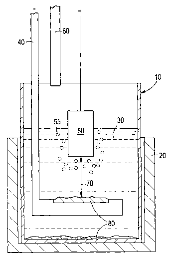
Fig. 1 is a partially schematic sectional view of an electrolytic cell
with an inert anode that is used to produce commercial purity aluminum in
accordance with the present invention.
Fig. 2 is a ternary phase diagram illustrating amounts of iron, nickel
and zinc oxides present in an inert anode that may be used to make commercial
purity aluminum in accordance with an embodiment of the present invention.
Fig. 3 is a ternary phase diagram illustrating amounts of iron, nickel
and cobalt oxides present in an inert anode that may be used to make
commercial
purity aluminum in accordance with another embodiment of the present
invention.
Fig. 1 schematically illustrates an electrolytic cell for the production
of commercial purity aluminum which includes an inert anode in accordance with
an embodiment of the present invention. The cell includes an inner crucible 10
inside a protection crucible 20. A cryolite bath 30 is contained in the inner
crucible
10, and a cathode 40 is provided in the bath 30. An inert anode 50 is
positioned in
the bath 30. An alumina feed tube 60 extends partially into the inner crucible
10
above the bath 30. The cathode 40 and inert anode 50 are separated by a
distance
70 known as the anode-cathode distance (ACD). Commercial purity aluminum 80
produced during a run is deposited on the cathode 40 and on the bottom of the
crucible 10.
As used herein, the term "inert anode" means a substantially non-
consumable anode which possesses satisfactory corrosion resistance and
stability
SU6ST1TUTE SHEET (RULE 26)
CA 02389341 2002-04-26
WO 01/32961 PCT/US00/29825
-3-
during the aluminum production process. In a preferred embodiment, the inert
anode comprises a cermet material.
As used herein, the term "commercial purity aluminum" means
aluminum which meets commercial purity standards upon production by an
electrolytic reduction process. The commercial purity aluminum comprises a
maximum of 0.2 weight percent Fe, 0.1 weight percent Cu, and 0.034 weight
percent Ni. In a preferred embodiment, the commercial purity aluminum
comprises
a maximum of 0.15 weight percent Fe, 0.034 weight percent Cu, and 0.03 weight
percent Ni. More preferably, the commercial purity aluminum comprises a
maximum of 0.13 weight percent Fe, 0.03 weight percent Cu, and 0.03 weight
percent Ni. Preferably, the commercial purity aluminum also meets the
following
weight percentage standards for other types of impurities: 0.2 maximum Si,
0.03
Zn and 0.03 Co. The Si impurity level is more preferably kept below 0.15 or
0.10
weight percent.
Inert anodes of the present invention preferably have ceramic phase
portions and metal phase portions. The ceramic phase typically comprises at
least
50 weight percent of the anode, preferably from about 70 to about 90 weight
percent. It is noted that for every numerical range or limit set forth herein,
all
numbers with the range or limit including every fraction or decimal between
its
stated minimum and maximum, are considered to be designated and disclosed by
this description.
The ceramic phase portions preferably comprise iron and nickel
oxides, and at least one additional oxide such as zinc oxide and/or cobalt
oxide.
For example, the ceramic phase may be of the formula; Ni,_X_y Fez_x My O;
where M
is preferably Zn and/or Co; x is from 0 to 0.5; and y is from 0 to 0.6. More
preferably X is from 0.05 to 0.2, and y is from 0.01 to 0.5. Table 1 lists
some
ternary Fe-Ni-Zn-O materials that may be suitable for use as the ceramic phase
of a
cermet inert anode.
SU8ST1TUTE SHEET (RULE 26)
CA 02389341 2002-04-26
WO 01/32961 PCT/US00/29825
-4-
TABLE 1
Sample Nominal Elemental WeightStructural
LD. Composition Percent Fe, Types
Ni, Zn
5412 NiFez04 48, 23.0, 0.15 NiFez04
5324 NiFez04 + Ni0 34, 36, 0.06 NiFez04, Ni0
E4 Zno.osNio.9sFezOa43, 22, 1.4 NiFez04 TU*
E3 Zno.,Nio.~Fez04 43, 20, 2.7 NiFez04 TU*
E2 Zno.zsNlo.~sFez~a40, 15, 5.9 NiFez04 TU'
E1 ZZno,zsNlo.~sFe,.9oO445, 18, 7.8 NiFez04 TU*
E Zno.sNio.sFez04 45, 12, 13 (ZnNi)Fez04, TP+
ZnOs
F ZnFez04 43, 0.03, 24 ZnFez04, TP+ Zn0
H Zno.sNiFe,.s04 33, 23, 13 (ZnNi)Fez04, NiOs
J Zno.sNi,.sFeO~ 26, 39, 10 NiFez04, MP +Ni0
L ZnNiFe04 22, 23, 27 (ZnNi)Fez04, Ni05,
Zn0
ZD6 Zr~.osNi,,osFe,.90440, 24, 1.3 NiFez04 TU'
ZDS Zno.,Ni,,,Fe,.gO~29, 18, 2.3 NiFez04 TU*
ZD3 Zno.~2Nio.9aFe,.gg0443, 23, 3.2 NiFez04 TU*
ZD1 ZnouzNio.9aFe,,8g0440, 20, 11 (ZnNi)Fez04 TU'
DH Zllo.,8N1o.96Fe1.R~442, 23, 4.9 NiFez04, TP +Ni0
DI Zno,oBNi,.,~Fe,.s0438, 30, 2.4 NiFez04, MP +NiO,
TU'
DJ Zno.,~Ni,.,Fe,.s0436, 29, 4.8 NiFez04, MP +Ni0
BC2 Zno,33Nlo_6~O 0.11, 52, 25 NiOs, TU'
TU means trace unidentified; +TP means trace possible;
+MP means minor possible; S means shifted peak.
Fig. 2 is a ternary phase diagram illustrating the amounts of Fez03,
Ni0 and Zn0 starting materials used to make the compositions listed in Table
1,
which may be used as the ceramic phases) of cermet inert anodes. Such inert
anodes may in turn be used to produce commercial purity aluminum in accordance
with the present invention.
In one embodiment, when Fez03, Ni0 and Zn0 are used as starting
materials for making an inert anode, they are typically mixed together in
ratios of
SUBSTITUTE SHEET (RULE 26)
CA 02389341 2002-04-26
WO 01/32961 PCT/US00/29825
-5-
20 to 99.09 mole percent NiO, 0.01 to 51 mole percent Fe203, and zero to 30
mole
percent ZnO. Preferably, such starting materials are mixed together in ratios
of 45
to 65 mole percent NiO, 20 to 45 mole percent Fe203, and 0.01 to 22 mole
percent
ZnO.
Table 2 lists some ternary Fez03/Ni0/Co0 materials that may be
suitable as the ceramic phase.
TABLE 2
Sample Nominal CompositionAnalyzed ElementalStructural Types
LD. Wgt. % Fe, Ni,
Co
CF CoFez04 44, 0.17, 24 CoFe,04
NCF1 Nio.SCoo.sFe2~a 44, 12, 11 NiFe,04
NCF2 Nio.~Coo.3Fe204 45, 16, 7.6 NiFez04
NCF3 Nio.~Coo.3Fe,.950442, 18, 6.9 NiFe204, TU*
NCF4 Nio.gSCoo.,SFe,,950444, 20, 3.4 NiFe204
NCFS Nio.85Coo.5Fe,.90445, 20, 7.0 NiFez04, NiO,
TU'
NF NiFeZ04 48, 23, 0 N/A
' TU means trace unidentified
Fig. 3 is a ternary phase diagram illustrating the amounts of Fe203,
Ni0 and Co0 starting materials used to make the compositions listed in Table
2,
which may be used as the ceramic phases) of cermet inert anodes. Such inert
anodes may in turn be used to produce commercial purity aluminum in accordance
with the present invention.
The cermet inert anodes used in accordance with a preferred
aluminum production method of the present invention include at least one metal
phase, for example, a base metal and at least one noble metal. Copper and
silver
are preferred base metals. However, other electrically conductive metals may
optionally be used to replace all or part of the copper or silver.
Furthermore,
additional metals such as Co, Ni, Fe, Al, Sn, Nb, Ta, Cr, Mo, W and the like
may
be alloyed with the base metal. Such base metals may be provided from
individual
or alloyed powders of the metals, or as oxides of such metals.
The noble metal preferably comprises at least one metal selected from
SUBSTITUTE SHEET (RULE 26)
CA 02389341 2002-04-26
WO 01/32961 PCT/US00/29825
-6-
Ag, Pd, Pt, Au, Rh, Ru, Ir and Os. More preferably, the noble metal comprises
Ag,
Pd, Pt, Ag and/or Rh. Most preferably, the noble metal comprises Ag, Pd or a
combination thereof. The noble metal may be provided from individual or
alloyed
powders of the metals, or as oxides of such metals, e.g., silver oxide,
palladium
oxide, etc.
Preferably, metal phases) of the inert electrode comprises at least
about 60 weight percent of the combined base metal and noble metal, more
preferably at least about 80 weight percent. The presence of base metal/noble
metal
provides high levels of electrical conductivity through the inert electrodes.
The base
metal/noble metal phase may form either a continuous phases) within the inert
electrode or a discontinuous phases) separated by the oxide phase(s).
The metal phase of the inert electrode typically comprises from about
50 to about 99.99 weight percent of the base metal, and from about 0.01 to
about
50 weight percent of the noble metal(s). Preferably, the metal phase comprises
from about 70 to about 99.95 weight percent of the base metal, and from about
0.05
to about 30 weight percent of the noble metal(s). More preferably, the metal
phrase
comprises from about 90 to about 99.9 weight percent of the base metal, and
from
about 0.1 to about 10 weight percent of the noble metal(s).
The types and amounts of base and noble metals contained in the
metal phase of the inert anode are selected in order to substantially prevent
unwanted corrosion, dissolution or reaction of the inert electrodes, and to
withstand
the high temperatures which the inert electrodes are subjected to during the
electrolytic metal reduction process. For example, in the electrolytic
production of
aluminum, the production cell typically operates at sustained smelting
temperatures
above 800°C, usually at temperatures of 900-980°C. Accordingly,
inert anodes used
in such cells should preferably have melting points above 800°C, more
preferably
above 900°C, and optimally above about 1,000°C.
In one embodiment of the invention, the metal phase comprises
copper as the base metal and a relatively small amount of silver as the noble
metal.
In this embodiment, the silver content is preferably less than about 10 weight
percent, more preferably from about 0.2 to about 9 weight percent, and
optimally
from about 0.5 to about 8 weight percent, remainder copper. By combining such
SUBSTITUTE SHEET (RULE 26)
CA 02389341 2002-04-26
WO 01/32961 PCT/US00/29825
_7_
relatively small amounts of Ag with such relatively large amounts of Cu, the
melting point of the Cu-Ag alloy phase is significantly increased. For
example, an
alloy comprising 95 weight percent Cu and 5 weight percent Ag has a melting
point
of approximately 1,000°C, while an alloy comprising 90 weight percent
Cu and 10
weight percent Ag forms a eutectic having a melting, point of approximately
780°C.
This difference in melting points is particularly significant where the alloys
are to
be used as part of inert anodes in electrolytic aluminum reduction cells,
which
typically operate at smelting temperatures of greater than 800°C.
In another embodiment of the invention, the metal phase comprises
copper as the base metal and a relatively small amount of palladium as the
noble
metal. In this embodiment, the Pd content is preferably less than about 20
weight
percent, more preferably from about 0.1 to about 10 weight percent.
In a further embodiment of the invention, the metal phase comprises
silver as the base metal and a relatively small amount of palladium as the
noble
metal. In this embodiment, the Pd content is preferably less than about 50
weight
percent, more preferably from about 0.05 to about 30 weight percent, and
optimally
from about 0.1 to about 20 weight percent. Alternatively, silver may be used
alone
as the metal phase of the anode.
In another embodiment of the invention, the metal phase comprises
Cu, Ag and Pd. In this embodiment, the amounts of Cu, Ag and Pd are preferably
selected in order to provide an alloy having a melting point above
800°C, more
preferably above 900°C, and optimally above about 1,000°C. The
silver content is
preferably from about 0.5 to about 30 weight percent of the metal phase, while
the
Pd content is preferably from about 0.01 to about 10 weight percent. More
preferably, the Ag content is from about 1 to about 20 weight percent of the
metal
phase, and the Pd content is from about 0.1 to about 10 weight percent. The
weight
ratio of Ag to Pd is preferably from about 2:1 to about 100:1, more preferably
from
about 5:1 to about 20:1.
In accordance with a preferred embodiment of the present invention,
the types and amounts of base and noble metals contained in the metal phase
are
selected such that the resultant material forms at least one alloy phase
having an
increased melting point above the eutectic melting point of the particular
alloy
SUBSTITUTE SHEET (RULE 26)
CA 02389341 2002-04-26
WO 01/32961 PCT/US00/29825
_g_
system. For example, as discussed above in connection with the binary Cu-Ag
alloy
system, the amount of the Ag addition may be controlled in order to
substantially
increase the melting point above the eutectic melting point of the Cu-Ag
alloy.
Other noble metals, such as Pd and the like, may be added to the binary Cu-Ag
alloy system in controlled amounts in order to produce alloys having melting
points
above the eutectic melting points of the alloy systems. Thus, binary, ternary,
quaternary, etc. alloys may be produced in accordance with the present
invention
having sufficiently high melting points for use as part of inert electrodes in
electrolytic metal production cells.
The inert anodes may be formed by techniques such as powder
sintering, sol-gel processes, slip casting and spray forming. Preferably, the
inert
electrodes are formed by powder techniques in which powders comprising the
oxides and metals are pressed and sintered. The inert anode may comprise a
monolithic component of such materials, or may comprise a substrate having at
least
one coating or layer of such material.
Prior to combining the ceramic and metal powders, the ceramic
powders, such as NiO, FeZ03 and Zn0 or CoO, may be blended in a mixer.
Optionally, the blended ceramic powders may be ground to a smaller size before
being transferred to a furnace where they are calcined, e.g., for 12 hours at
1,250°C.
The calcination produces a mixture made from oxide phases, for example, as
illustrated in Figs. 2 and 3. If desired, the mixture may include other oxide
powders such as Cr203.
The oxide mixture may be sent to a ball mill where it is ground to an
average particle size of approximately 10 microns. The fine oxide particles
are
blended with a polymeric binder and water to make a slurry in a spray dryer.
The
slurry contains, e.g., about 60 wt.% solids and about 40 wt.% water. Spray
drying
the slurry produces dry agglomerates of the oxides that may be transferred to
a
V-blender and mixed with metal powders. The metal powders may comprise
substantially pure metals and alloys thereof, or may comprise oxides of the
base
metal and/or noble metal.
In a preferred embodiment, about 1-10 parts by weight of an organic
polymeric binder are added to 100 parts by weight of the metal oxide and metal
SU6ST1TUTE SHEET (RULE 26)
CA 02389341 2002-04-26
WO 01/32961 PCT/LTS00/29825
-9-
particles. Some suitable binders include polyvinyl alcohol, acrylic polymers,
polyglycols, polyvinyl acetate, polyisobutylene, polycarbonates, polystyrene,
polyacrylates, and mixtures and copolymers thereof. Preferably, about 3-6
parts by
weight of the binder are added to 100 parts by weight of the metal oxides,
copper
and silver.
The V-blended mixture of oxide and metal powders may be sent to a
press where it is isostatically pressed, for example at 10,000 to 40,000 psi,
into
anode shapes. A pressure of about 20,000 psi is particularly suitable for many
applications. The pressed shapes may be sintered in a controlled atmosphere
furnace supplied with an argon-oxygen gas mixture. Sintering temperatures of
1,000-1,400°C may be suitable. The furnace is typically operated at
1,350-1,385°C
for 2-4 hours. The sintering process burns out any polymeric binder from the
anode
shapes.
The sintered anode may be connected to a suitable electrically
conductive support member within an electrolytic metal production cell by
means
such as welding, brazing, mechanically fastening, cementing and the like.
The gas supplied during sintering preferably contains about 5-3,000
ppm oxygen, more preferably about 5-700 ppm and most preferably about 10-350
ppm. Lesser concentrations of oxygen result in a product having a larger metal
phase than desired, and excessive oxygen results in a product having too much
of
the phase containing metal oxides (ceramic phase). The remainder of the
gaseous
atmosphere preferably comprises a gas such as argon that is inert to the metal
at the
reaction temperature.
Sintering anode compositions in an atmosphere of controlled oxygen
content typically lowers the porosity to acceptable levels and avoids bleed
out of the
metal phase. The atmosphere may be predominantly argon, with controlled oxygen
contents in the range of 17 to 350 ppm. The anodes may be sintered in a tube
furnace at 1,30°C for 2 hours. Anode compositions sintered under these
conditions
typically have less than 0.5% porosity when the compositions are sintered in
argon
containing 70-150 ppm oxygen. In contrast, when the same anode compositions
are
sintered for the same time and at the same temperature in an argon atmosphere,
porosities are substantially higher and the anodes may show various amounts of
SUBSTITUTE SHEET (RULE 26)
CA 02389341 2002-04-26
WO 01/32961 PCT/US00/29825
- 10-
bleed out of the metal phase.
The inert anode may include a cermet as described above
successively connected in series to a transition region and a nickel end. A
nickel or
nickel-chromium alloy rod may be welded to the nickel end. The transition
region,
for example, may include four layers of graded composition, ranging from 25
wt.%
Ni adjacent the cermet end and then 50, 75 and 100 wt.% Ni, balance the
mixture
of oxide and metal powders described above.
We prepared several inert anode compositions in accordance with the
procedures described above having diameters of about 5/8 inch and length of
about
5 inches. These compositions were evaluated in a Hall-Heroult test cell
similar to
that schematically illustrated in Fig. 1. The cell was operated for 100 hours
at
960°C, with an aluminum fluoride to sodium fluoride bath ratio of 1.1
and alumina
concentration maintained at about 7-7.5 wt.%. The anode compositions and
impurity concentrations in aluminum produced by the cell are shown in Table 3.
1 S The impurity values shown in Table 3 represent the average of four test
samples of
the produced metal taken at four different locations after the 100 hour test
period.
Interim samples of the produced aluminum were consistently below the final
impurity levels listed.
SUBSTITUTE SHEET (RULE 26)
CA 02389341 2002-04-26
WO 01/32961 PCT/US00/29825
11 -
N
~h N ~n l~ M r
N 00 N 01 N M ~ M ~ N O W vp
O O -r O O ~ ~ M N - ~ O O O O .~ O
O O O O O O O O O O O O O O O O O O
d' N d w n (~
N ~ M V'1M ~ O~ M \O .--~ .~ ~ M '~hN ..~00
U o o ~ 0 0 0 0 .-..-.o ~ 0 0 0 0 0 0
0 0 0 0 0 0 0 0 0 0 0 0 0 0 0 0 0 0
O WO I~ O WD o0 ~ ~ I~ N N oo N I~
N M ~t M '~tM ~n .-~.~ N O N .--.
O O O O O O O O O O O O O O O O O O
."
I~ 00 O v7 M O
N ~O oo t~ O M o0
O .~ .~ ,~ .-~N N
O O O O O O O
M
W
a
H
0
..,
.
.
.
0
0
f~1 f~1 f~1M t~1M M M f'~1N1 f1
O O O O O O O O O O O
t1 t'1N t'1Nt N t1 N1 t~1N N N N N N N N N
O O ' O O ~' O O O ~' ' ~' ~'
N N w N N w N N N w w w w w w w w w
~r ~n ~ ~ ~r ~ ~r ~r ~r
w w ~n w w o w w w ~n N o 0 0 0 0 0 0
,~ ~. r-.
0 0 ~, o o ~ 0 0 0 ~ ~n ~n ~n ~n ~n ~n ~n V,
~r ~ ~ v ~ ~ ~r ~ ~r
O O ~ O O O O O O O O
O O O O O O O
z z ~ z z z z z z z z z
z z ~ z z ~ z z z
N N ~O N N M N N N V' I~ I~ I~ t~ I~ l~ I~ I~
d' '~tN d' ~h <t'~h d' d' Wit'N N N N N N N N
i ~
U U U U U U U U U U U U U U U U U U
~t ~t ~t ~ ~ o ~ ~n ~n .-.~ ~ ~t ~ ~t ~ ~t
do on an an cn en cn on tincn on an an op on on cn on
d d d d d d d d d d d d d d d d d d
M M M M M N M N N M .-r~ ~ .-~ rr .--a.~ .~
O
z
O N M ~' ~ ~O I~ 00 O~ ~ '-'N M ~ V7 ~O I~ 00
rr W --t~
SUBSTITUTE SHEET (RULE 26)
CA 02389341 2002-04-26
WO 01/32961 PCT/US00/29825
- 12-
l~ M M M ~' I~ 00 ~' .-.rM
V' N '~ I~ ~' N 00 00 00 N ~ 00 V7 N N N .-
O .~ ,-,O .-~O O O .--~O ,-..--~O O N .~ O O
O O O O O O O O O O O O O O O O O O O
d' N ~ I~ 00 01
U N a\ d' W O ~n M ~n ~n M ~n ~ .--~.-~~n N N 0
o 0 0 0 0 0 0 0 0 0 0 0 0 0 0 0 0 0
0 0 0 0 0 0 0 0 0 0 0 0 0 0 0 0 0 0 0
W D ~ 00 0~0v1 N oo .-. ,--~N N o~o'p .~ o~o
w N .~ 'fit~ .~ .--rN .--iN N .~ .~ .~ .-r.--n N
.~ -,
O O O O O O O O O O O O O O O O O O O
~_
M .--i~ .~ ~ .--r00 ,~ N M ~ 00 ,..~~O 01 .~ Ir V1 01
Q\ O d- a\ ~- O O O ~n O 'n M N ~n ~ ~t O O I~
.- N .~ ,-.N N N N N N N N N N .~ N .--~.~ N
O O O O O O O O O O O O O O O O O O O
O
O
O~ O O O O O O O N O
4J N ~ ~ N ~ ~ N
O -, w -, w w -, w ., w -, .~ -, ., '-'' O p O
U O N O N N O N O N O '~,O O '~,O N
ap ~ a~ ~ ~ ai Q' ai ~ ap O ap ap O a~ Z o
w ~ w ~ ~ w ~ w ~ w ai w w ai N w ' O
O "' O " "' O "' O "' O w O O w M O
_ _ _ _ _ O~ 01 O N
l~ O l~ O O t~ O I~ O I~ ~n l~ l~ V'1~' l~ p
~-r z z z z V7 V7
O oo O op oo O op O op O O O O O O O z O N
N '" N N N cV " w O
O ~ O O ~ O ~ O ~ ~ ~ ~ ~ oo ~ ,-r w
1 ~. 01 ~ ~ 01 ,y-~,~01 ~ 01 M 01 01 M ~. Ov ~
N c~ N N ~ N ~ N ~ ~ ~ ~ ~ o
N ~n N v1 ~n N 'n N V~ N N N N N ~ N ~ U
O ~ O
U U U U U U U U U U U U U U U U U
~t ~r ~r ~r ~ ~ ~ ~ ~ ~ ~ ~ ~r d~ N d' ,
on tin do a4 cn do bn cn cn an a4 on c~ a4 b an b b
d d d d d d d d d d d d d d a, d w a..a,
.-r.--.~.~ .~ .--m--~.~ .~ ..-,.--~,--.~,~ ,~ .--~.~ .--iM .-,
O
z
a\ O .-.N M d' ~n ~ t~ oo O~ O ~ N M d' ~n ~O I~
, ~ N N N N N N N N N N M M M M M M M M
SUHST1TUTE SHEET (RULE 26)
CA 02389341 2002-04-26
WO 01/32961 PCT/US00/29825
-13-
00 ~n ~ ~o ~n d' ~ t~ o~ oo ~n
M o0 ~O o0 ~O N ~ M o0 00 00 N d' M v0 N N I~ N
O O O O O O O O O O ~ O O O M O O O O
C O O O O O O O O O O O O O O O O O O
M I~ ~ M ~t ~ N N ~ d' Q1 O M W O N ~n N
U o 0 0 0 0 0 0 0 0 0 0 0 0 0 0 0 0 0 0
0 0 0 0 0 0 0 0 0 0 0 0 0 0 0 0 0 0 0
~O ~ ~ M 00
N .-r.~ 41 .~ 00 M 00 O~ V'1t~ .~ V'tI~ I~ I~ V O~ M
1
w .-..-~O ,~ r. O .~ O M N M .-~.~ N N O
O O O O O O O O O O O O O O O O O O O
.'.,
M 01 l~ ~ 00 N O ~ N I~ O M 01 Q1 ~ N
p Ow n N M o0 ~t ~ ~O -' N ~' oo O l~ I~ N ~ Ov
r. N .-~,~ .-..~ r-..-.N N .~ .~ N N .~ M N .-,
O O O O O O O O O O O O O O O O O O
O
0
N ~ ~ N ~ N N N
00 .~ 00 00 00 00
~
O ~ ~~ ; ~ ~; vo y o
0 0 O N O "'_'0 0 "'~O '-"'_'"'
O O ' ~ O ~ O O O
O O N N N ,~ N w w w
O O N N O t~ , O l~ ai ~ "~ a~ ,-,a~ N ai
O N N O O N ;~ O i~ M tn ~ M ~ M M M
O 0 . 0 a~ O N ~ ,'r;~'?,'r;N N N
N N N N 0 N m n mi Vi ~i
G) G7 ' ~ ~ z ~n ~ O ~n O ~, ~n .n
O 0 0 0 . z . . . .
~ w' w ~ '':O ~ ~ O ~ O O O
O O '~ ~' ~, z_ N ~ z_ ~ z_ z_ z_
~ ~ O O O ~ ~ ~1 V~ ~ N
~~ N ~ ~' ' v0 ~n O ~ ~~ N ~ ~ N ~ N N N
N ..
N M M O O ~' O_ z ~, ~ t~ N N l~ N I~ I~ I~
M M ~ ~ z ~ p z M N fi,N O V N U N N N
O O
ri M ~ ~ N ~ z N ~ N ~ U ~ ~ U ~' U U U
'd ~ N ~ ~ N v N =
O O irj ~ ~n p . ~ O ~ O O O
0 o z .
O O O O . . .
M ~ ~ ~ ~
O ~ M ' n M d d d ~ ~ O
~ a ; O ~' ~' O ~' O O
O ~, , '~ d ~ d ~ '~ GO ~ ~ bA ~ d0 d0 by
U d ~ d d ~ ~ d d d d ~ d ~ ~ d
U ' ~ ' o ~ ~ a U ~ ~ ~ ' ~ '
'. .... .J '. ...
b O b O O b ~ O pp N O pp O pp pp pp
~ ~o c~.-o -d w '-;-d d b ~o d b d d d
a, a. a, ~n a~ a, ~n ~ a~ ~ a~ as ~ a, vo w O
~ "' 'n r~ o -~ ~ o ~ ,-~oo ,-. .-.~oo ~ 00 00 00
.~ 0 0 0 0 0 0 0 .-.o .-:o o .-:o
0
z
0o O~ O .-~N M ~!''n ~O I~ o0 O~ O ~ N M d' ~w 0
M M ~ ~ ~' ~ d' ~ ~' ~ d' ~ tn V'1V1 ~n V'7V1 V'1
SUBSTITUTE SHEET (RULE 26)
CA 02389341 2002-04-26
WO 01/32961 PCT/LTS00/29825
- 14-
I
i 0 0
0 0
M
U o 0
0 0
o
0 0
..,
N .-r
O O ~
N N
O O
~ N
O
tyt
N O
O ~ M
N
O.
~ O
o N z
U
N
O N
U
U
0
U ~
O O
N
II
O o0
0
z
~,
SU9ST1TUTE SHEET (RULE 26)
CA 02389341 2002-04-26
WO 01/32961 PCT/US00/29825
- 15 -
The results in Table 3 show low levels of aluminum contamination
by the inert anodes. In addition, the inert anode wear rate was extremely low
in
each sample tested. Optimization of processing parameters and cell operation
may
further improve the purity of aluminum produced in accordance with the
invention.
Inert anodes are particularly useful in electrolytic cells for aluminum
production operated at temperatures in the range of about 800-1,000°C.
A
particularly preferred cell operates at a temperature of about 900-
980°C, preferably
about 930-970°C. An electric current is passed between the inert anode
and a
cathode through a molten salt bath comprising an electrolyte and an oxide of
the
metal to be collected. In a preferred cell for aluminum production, the
electrolyte
comprises aluminum fluoride and sodium fluoride and the metal oxide is
alumina.
The weight ratio of sodium fluoride to aluminum fluoride is about 0.7 to 1.25,
preferably about 1.0 to 1.20. The electrolyte may also contain calcium
fluoride,
lithium fluoride and/or magnesium fluoride.
While the invention has been described in terms of preferred
embodiments, various changes, additions and modifications may be made without
departing from the scope of the invention as set forth in the following
claims.
SU8ST1TUTE SHEET (RULE 26)