Language selection

Search

Patent 2389455 Summary

Third-party information liability

Some of the information on this Web page has been provided by external sources. The Government of Canada is not responsible for the accuracy, reliability or currency of the information supplied by external sources. Users wishing to rely upon this information should consult directly with the source of the information. Content provided by external sources is not subject to official languages, privacy and accessibility requirements.

Claims and Abstract availability

Any discrepancies in the text and image of the Claims and Abstract are due to differing posting times. Text of the Claims and Abstract are posted:

  • At the time the application is open to public inspection;
  • At the time of issue of the patent (grant).
(12) Patent: (11) CA 2389455
(54) English Title: HYDRAULICALLY ASSISTED RESTRAINT DEVICE
(54) French Title: DISPOSITIF D'ARRIMAGE A ASSISTANCE HYDRAULIQUE
Status: Expired and beyond the Period of Reversal
Bibliographic Data
(51) International Patent Classification (IPC):
  • B65G 69/28 (2006.01)
  • F16F 9/19 (2006.01)
(72) Inventors :
  • CHRISTIAAN, STOLK (Canada)
(73) Owners :
  • RENUM HYDRAULICS LTD.
(71) Applicants :
  • RENUM HYDRAULICS LTD. (Canada)
(74) Agent: EUGENE J. A. GIERCZAKGIERCZAK, EUGENE J. A.
(74) Associate agent:
(45) Issued: 2009-12-08
(22) Filed Date: 2002-06-06
(41) Open to Public Inspection: 2003-12-06
Examination requested: 2004-04-16
Availability of licence: N/A
Dedicated to the Public: N/A
(25) Language of filing: English

Patent Cooperation Treaty (PCT): No

(30) Application Priority Data: None

Abstracts

English Abstract

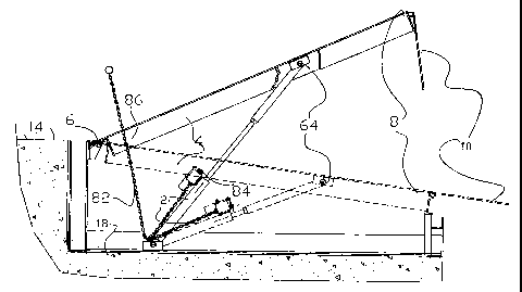
A device for restraining the upward movement of a dock comprising a hydraulic cylinder having a fixed end; a piston slideably disposed in said cylinder so as to define opposed first and second chambers; a rod having one end connected to said slideable piston, extending through said first chamber and having another end adapted for connection to said dock; hydraulic reservoir containing hydraulic fluid communicating with said first chamber; valve means disposed between said reservoir and said first chamber, said valve means having open position permitting said hydraulic fluid to flow from said first chamber to said reservoir and extending said rod in response to said upward movement of said dock; a closed position stopping the flow of said hydraulic fluid from said first chamber to said reservoir and restraining the upward movement of said dock.


French Abstract

Un dispositif d'arrimage du mouvement ascendant d'un quai comprenant un vérin hydraulique ayant une extrémité fixe; un piston logé dans ledit vérin de manière à ce que le piston soit coulissant pour définir la première chambre et la deuxième chambre opposées l'une à l'autre; une tige ayant une extrémité reliée audit piston coulissant, se prolongeant à travers ladite première chambre et une deuxième extrémité adaptée pour être reliée audit quai; un réservoir hydraulique contenant un fluide hydraulique communiquant avec ladite première chambre; ledit système de soupape disposé entre ledit réservoir et ladite première chambre, ledit système de soupape ayant une position ouverte permettant audit fluide hydraulique de s'écouler de ladite première chambre vers ledit réservoir et rallongeant ladite tige en réponse audit mouvement ascendant du quai; une position fermée arrêtant le débit dudit fluide hydraulique de ladite première chambre vers ledit réservoir et causant l'arrimage du mouvement ascendant dudit quai.

Claims

Note: Claims are shown in the official language in which they were submitted.


12
CLAIMS
The embodiment of the invention in which an exclusive property or privilege is
claimed are
defined as follows:
1. A device for restraining the upward movement of a dock comprising:
(a) hydraulic cylinder having:
(i) a fixed end;
(ii) a piston slideably disposed in said cylinder so as to define opposed
first
and second chambers;
(iii) a rod having one end connected to said slideable piston, extending
through said first chamber and having another end connected directly
to said dock;
(b) hydraulic reservoir containing hydraulic fluid communicating only with
said
first chamber through a valve means disposed between said reservoir and said
first chamber;
said valve means having:
(i) an open position permitting said hydraulic fluid to flow from said first
chamber to said reservoir and extending said rod in response to said
upward movement of said dock;
(ii) a closed position stopping the flow of said hydraulic fluid from said
first chamber to said reservoir and restraining the upward movement of
said dock;
(c) said second chamber including a hole to vent to the atmosphere.
2. A device as claimed in claim 1 wherein said valve means comprises a check
valve.
3. A device as claimed in claim 2 wherein said valve means further includes
bypass
means for permitting hydraulic fluid to flow from said first chamber to said
reservoir when
said hydraulic fluid reaches a preselected fluid pressure so as to extend said
rod.

13
4. A device as claimed in claim 1 wherein said valve means comprises an
electric
operated lock valve for opening and closing the communication of said
hydraulic fluid
between said reservoir and said first chamber electrically.
5. A device as claimed in claim 4 wherein said electric operated lock valve
comprises a
solenoid valve.
6. A device as claimed in claim 1 wherein said valve means includes a bypass
valve.
7. A device as claimed in claim 6 wherein said bypass valve is adapted to open
at a pre-
selected force.
8. A device for restraining the upward movement of a dock comprising:
(a) hydraulic cylinder having:
(i) a fixed end;
(ii) a piston slideably disposed in said cylinder so as to define opposed
first
and second chambers;
(iii) a rod having one end connected to said slideable piston, extending
through said first chamber and having another end adapted for
connection to said dock;
(b) hydraulic reservoir containing hydraulic fluid communicating only with
said
first chamber through a check valve disposed between said reservoir and said
first chamber;
(c) said valve means having:
(i) open position permitting said hydraulic fluid to flow from said first
chamber to said reservoir and extending said rod in response to said
upward movement of said dock;
(ii) a closed position stopping the flow of said hydraulic fluid from said
first chamber to said reservoir and restraining the upward movement of
said dock;

14
(d) said second chamber including a hole to vent to the atmosphere
wherein said check valve includes:
(a) a seat;
(b) a ball adapted to bear against said seat;
(c) spring means for urging said ball and seat together in said closed
position.
9. A device as claimed in claim 8 including means associated with said check
valve
means for separating said ball from said seat in said open position.
10. A device as claimed in claim 9 wherein said separating means comprises a
pull chain
associated with said check valve.
11. A device as claimed in claim 10 wherein said spring is biased to urge said
ball and
valve together in said closed position.
12. A device for restraining the upward movement of a dock comprising:
(a) a hydraulic cylinder having:
(i) a fixed end;
(ii) a piston slideably disposed in said cylinder so as to define opposed
first
and second chambers;
(iii) a rod having one end connected to said slideable piston, extending
through said first chamber and having another end connected to said
dock;
(b) hydraulic reservoir containing hydraulic fluid communicating only with
said
first chamber through a valve means disposed between said reservoir and said
first chamber,
(c) said valve means having:

15
(i) an open position permitting said hydraulic fluid to flow from said first
chamber to said reservoir and extending said rod in response to said
upward movement of said dock;
(ii) a closed position stopping the flow of said hydraulic fluid from said
first chamber to said reservoir and restraining the upward movement of
said dock;
(d) said second chamber including a hole to vent to the atmosphere wherein
said
valve means comprises an electric operated lock valve for opening and closing
the communication of hydraulic fluid between said reservoir and sad first
chamber.
13. An assembly for holding a dock relative a vehicle comprising:
(a) a dock having one end moveable relative said vehicle;
(b) means for urging said one end of said dock upwardly relative said vehicle;
(c) a hydraulic cylinder having:
(i) a fixed end relative said dock;
(ii) a piston slideably disposed in said cylinder so as to define opposed
first
and second chambers;
(iii) a rod having one end connected to said slideable piston extending
through said first chamber and having another end connected to said
moveable dock;
(d) hydraulic reservoir containing hydraulic fluid communicating only with
said
first chamber through a valve means disposed between said reservoir and said
first chamber;
(e) said valve means having:
(i) an open position permitting said hydraulic fluid to flow from said first
chamber to said reservoir so as to extend said rod in response to said
upward movement of said dock;

16
(ii) a closed position stopping the flow of said hydraulic fluid from said
first chamber to said reservoir and restraining said urging means from
urging said upward movement of said one end of said dock;
(f) means for moving said valve means between said open and closed positions;
(g) said second chamber including a hole to vent to the atmosphere.
14. An assembly as claimed in claim 13 wherein said valve means is selected to
stop
extending said rod at a selected hydraulic pressure.
15. An assembly as claimed in claim 14 wherein said rod automatically extends
at a
selected upward force of said dock.
16. An assembly as claimed in claim 15 wherein said dock as a pivotable end
and a distal
end.
17. A method of holding down a spring loaded dock having a pivotable end and a
distal
end with a hydraulic cylinder, said hydraulic cylinder having a valve and a
piston slideably
disposed in said cylinder so as to define opposed first and second chambers, a
hydraulic
reservoir containing hydraulic fluid communicating only with the first chamber
through said
valve_and a rod having one end connected to said piston, said rod extending
through said first
chamber and having another end extending outwardly of said first cylinder and
connected to
said moveable dock comprising the steps of:
(a) fixing one end of said cylinder relative said dock;
(b) connecting said another end of said rod to said dock;
(c) opening said valve so as to extend said rod as said spring loaded dock
rises;
and
(d) closing said valve to lock said rod in said position and hold said spring
loaded
dock.
18. A method as claimed in claim 17 including the steps of moving said valve
from said
closed position to said open position.

Description

Note: Descriptions are shown in the official language in which they were submitted.


CA 02389455 2002-06-06
-2-
Description
HYDRAULICALLY ASSISTED RESTRAINT DEVICE
Field of Invention
This invention relates to a device for restraining the upward movement of a
dock and particularly relates to a hydraulically assisted restraint device.
This
invention also relates to an assembly for holding a dock relative a vehicle as
well
as a method of holding down a spring loaded dock having a pivotal end and a
moveable distal end.
Background Art
Dock levellers generally comprise hinged ramp structures which are
disposed in vehicle loading docks to provide a ramp extending between a
vehicle
load bed and the loading dock to facilitate movement of cargo between the dock
and the vehicle and to overcome any difference in elevation between the floor
of
the vehicle load bed and the dock.
Various structures and devices have heretofore been manufactured and
sold some of which include extension lip members. Each of the devices and
assemblies in the prior art are subjected to the change in height of the
vehicle
load bed relative the dock during loading and unloading operations.
Generally speaking the dock has a hinged or pivotal end and a moveable
distal end which can move vertically relative to the vehicle's load bed.
Accordingly as the loaded vehicle is backed up towards the dock the distal end
is
adjusted so as to rest generally at the edge of the load bed of the vehicle.
The
suspension system of a vehicle is generally compressed due to the weight of
the
cargo when initially adjusting the dock relative to the load bed. Upon
unloading
of the cargo, whether by pallet truck or otherwise the weight of the cargo
diminishes and the potential energy of the suspension system in the vehicle

IL=y.Ipd I 1 11
CA 02389455 2002-06-06
-3-
increases since the weight of the cargo is no longer there to balance the
force in
the suspension system which generally includes springs. Accordingly such dock
levelling devices and apparatus are subject to rapid wear and unwanted damage
as a result of this type of movement.
Various devices have heretofore been devised. For example, U.S. Patent
No. 6,327,733 B1 relates to a pit type dock leveller having a frame adapted to
be
fixedly mounted at a dock with a deck, pivotally mounted to the frame at one
end
thereof, and having a pivotal lip at the other end. A spring is mounted to the
deck
and the frame to support and raise the deck. A hydraulic actuator is coupled
to
the deck and to a pivotal lirik member that is mounted to the frame. In a
powered
mode, the hydraulic unit acts as a power assist for the springs to move the
deck
from a generally horizontal stored position to an operative position. Such
device
positions the dock by use of an electric hydraulic power utilizing the
hydraulic
cylinder to move the dock up.
Moreover U.S. Patent No. 6,163,913 discloses a dock leveller including a
pivotal mounted ramp and a lip member pivotally mounted to the distal end of
the
ramp and moveable between an extended position and a depending position for
forming a path between a loading dock and a load bed of a vehicle. A motor
operated linear power screw type actuator is connected to the ramp for moving
the ramp to an elevated position and includes an extension member which is
engageable with a second tube and telescope relationship in such a way that
the
actuator tube may be controlled after positioning the ramp to engage the load
bed
of a vehicle so that the actuator is not subject to forces exerted by the ramp
during oscillatory movement while the vehicle is being loaded or unloaded.
This
device generally describes a hydraulic cylinder used to hold up the dock and
protect the dock from sudden downward movements.
Moreover U.S. Patent No. 5,832,554 relates to a dock leveller typically
powered by electric actuator or other motive source having a frame and a deck
pivotally mounted to the frame.

CA 02389455 2002-06-06
-4-
Furthermore U.S. Patent No. 5, 856,355 relates to a safety device for a
vertically stored dock leveller. Electric power is required to allow the dock
leveller
to be lowered and the dock leveller will stop if electrical power to the
control
circuit is interrupted.
Furthermore U.S. Patent No. 5,526,545 also relates to a dock moveable
by hydraulic cylinder which mechanism returns a loading dock into a stored
position automatically.
These and other devices illustrate the use of devices which hold up docks.
There have also been mechanical devices such as wheel style pulley systems
which hold docks downwardly as well as mechanical rachet type hold down
systems, which can come apart if subjected to increased upward pressure due to
unloading of a vehicle.
It is an object of this invention to provide an improved hydraulic hold down
system.
It is an object of this invention to provide an improved device for
restraining the upward movement of a dock and particularly an assembly for
holding a dock relative a vehicle.
Disclosure of Invention
It is an aspect of this invention to provide a device for restraining the
upward movement of a dock comprising a hydraulic cylinder having a fixed end;
a
piston slideably disposed in said cylinder so as to define opposed first and
second chambers; a rod having one end connected to said slideable piston,
extending through said first chamber and having another end adapted for
connection to said dock; hydraulic reservoir containing hydraulic fluid
communicating with said first chamber; valve means disposed between said
reservoir and said first chamber, said valve means having open position
permitting said hydraulic fluid to flow from said first chamber to said
reservoir and
extending said rod in response to said upward movement of said dock; a closed

CA 02389455 2002-06-06
position stopping the flow of said hydraulic fluid from said first chamber to
said
reservoir and restraining the upward movement of said dock.
It is a further aspect of this invention to provide an assembly for holding a
dock relative a vehicle comprising a dock having one end moveable relative
said
vehicle; means for urging said one end of said dock upwardly relative said
vehicle; a hydraulic cylinder having a fixed end relative said dock; a piston
slideably disposed in said cylinder so as to define opposed first and second
chambers; a rod having one end connected to said slideable piston extending
through said first chamber and having another end connected to said moveable
dock; hydraulic reservoir containing hydraulic fluid communicating with said
first
chamber; valve means disposed between said reservoir and said first chamber
having an open position permitting said hydraulic fluid to flow from said
first
chamber to said reservoir so as to extend said rod in response to said upward
movement of said dock; a closed position stopping the flow of said
hydraulic'fluid
from said first chamber to said reservoir and restraining said urging means
from
urging said upward movement of said one end of said dock; means for moving
said valve means between said open and closed positions.
It is yet another aspect of this invention to provide a method of holding
down a spring loaded dock having a pivotable end and a distal end with a
hydraulic cylinder having a valve and a piston slideably disposed in said
cylinder
so as to define opposed first and second chambers, and a rod having one end
connected to said piston, said rod extending through said first chamber and
having another end extending outwardly of said first cylinder and connected to
said dock comprising the steps of fixing one end of said cylinder relative
said
dock; connecting said another end of said rod to said dock; opening said valve
so
as to extend said rod as said spring loaded dock rises; closing said valve to
lock
said rod in said position and hold said spring loaded dock.
Brief Description of Drawings
Fig. I is a perspective view of the assembly for holding a dock relative a
vehicle.

~ ~ 1õ,I I ~J VI
CA 02389455 2002-06-06
-6-
Fig. 2 is a full cross-sectional view through the hydraulic cylinder.
Fig. 3 is a side elevational view showing the hydraulic cylinder in a closed
position and an open position.
Fig. 4 is a schematic diagram of the hydraulic cylinder.
Fig. 5 is another side elevational view of the invention.
Best Mode for Carrying Out the Invention
In the description that follows, like parts are marked throughout the
specification and the drawings with the same respective reference numerals.
The drawings are not necessarily to scale and in some instances proportions
may
have been exaggerated in order to more clearly depict certain features of the
invention.
Figures 1 and 2 illustrate the device 2 for restraining the upward
movement of a dock 4. The dock 4 is generally comprised of a hinged or pivotal
end 6 and a distal end 8 which may include an extendable lip 10 which is well
known to those persons skilled in the art. The distal end 8 is adapted to be
moved vertically upwardly or downwardly relative to a vehicle 12 as shown in
Figures 3 and 4. The distal end 8 is adapted to be moved vertically up or down
in
a manner to be described herein so as to level the height H of the vehicle 12
relative to the height h of a loading platform 14.
The dock 4 may include a frame 16 and may pivot about the pivotable end
6 above a pit 18 which pit 18 may include the various mechanisms for movement
of the dock to be described herein.
Generally speaking the dock 4 is urged upwardly by means of structure
which causes the dock to be moved upwardly. As shown in Figure 1, such
upwardly moving means may comprise of spring loaded means 20 having a
plurality of springs 22, 24, 26 and 28. One end 30 of each of the springs 22,
24,

~ ~ - ~ ~ ~1.W'l~ f i~I ,11 ;:
CA 02389455 2002-06-06
-7-
26 and 28 are fixed or anchored to the pit 18 and the other end 32 of each of
the
springs 22, 24, 26 and 28 are connected to one end of an arm assembly 34 so as
to cause the arm 36 to rotate about pivot 38 and thereby urge the dock
upwardly.
A roller 40 is generally utilized in order to reduce friction.
Any spring biasing means or upwardly moveable dock means may be
utilized and the invention should not be limited to the spring loaded means
shown
in Figure 1.
Accordingly the dock is biased in an upward position by means of the
spring loaded means 20.
A device 2 is utilized to restrain the upward movement of the dock.
Generally speaking the device comprises a hydraulic cylinder 50 having a fixed
end 52 and a piston 54 slideably disposed in the cylinder so as to define
opposed
first chamber 56 and second chamber 58. A rod 60 has one end 62 connected to
the slideable piston 54 and extends through the first chamber 56 and has
another
end 64 connected to the dock 4. A hydraulic reservoir 66 contains hydraulic
fluid
68 for communicating with the first chamber 56. In other words, the first
chamber
56 is filled with hydraulic fluid. Any suitable hydraulic fluid can be
utilized, one
example of which includes hydraulic aircraft fluid.
A valve means 70 is disposed between the reservoir 66 and the first
chamber 56.
Figure 4 illustrates one example of the valve means 70 which comprises a
ball 72, a seat 74. The valve means 70 as shown in Figure 4 generally
comprises a check valve which is biased in a closed or blocked position. The
closed or blocked position corresponds to the ball 72 bearing against the seat
74.
Hydraulic fluid 68 can not communicate with the reservoir 66 in the closed
position since the ball 72 bears against the seat 74. However, the ball 72 may
be
separated from the seat 74 by utilizing separating means 80 which in the
figures
comprise a pull chain 82. The pull chain 82 is connected at one end 84 to an
assembly which will separate the ball 72 from the seat 74 thereby permitting

CA 02389455 2002-06-06
-8-
communication of the hydraulic fluid 68 from the first chamber 56 to the
reservoir
66. Upon moving the valve means 70 to an open or unblocked position the
upward movement of the spring means 20 will cause the deck 4 to move
upwardly or pivot about the pivot end 6 thereby extending the rod 60 since the
end of the rod 64 is connected to the deck 4.
The pull chain 82 extends through an appropriate aperture 86 located in
the deck 4. Accordingly a user may pull on the pull chain 86 thereby releasing
the locking device of the hydraulic cylinder 2 and therefore the springs 22
move
the deck upwardly relative a vehicle. As the deck 4 moves upwardly by means of
the spring means 20 the rod 60 is extended whereby the volume of the first
chamber 56 diminishes while the volume of the second chamber 58 enlarges.
Upon releasing the check valve 86 the valve means 70 closes stopping further
communication of hydraulic fluid 68 from the first chamber 56 to the reservoir
68.
Accordingly the position of the deck 4 is "locked" and the hydraulic device 2
restrains further upward movement of the dock 4.
The spring-loaded means 20 is selected to lift the dock 4 when the chain is
released. Therefore once a user pulls the pull chain 80 the check valve 70
opens
permitting hydraulic fluid 68 to move from the first cylinder 56 back into the
reservoir 68 extending the rod 60 as the distal end 8 of the dock moves
upwardly.
Thereafter a vehicle may be backed up against the dock 4 in which event
the distal end 8 would be higher than the height H of the vehicle 12.
Thereafter a
person may walk along the dock causing the distal end 8 to move downwardly
due to the weight of the person until the height is substantially the same as
the
height H of the vehicle. The rod 60 in such event would be forced downwardly
opening the check valve 70 causing hydraulic fluid to flow from the reservoir
66
back into the first chamber 56 thereby slightly expanding the volume of the
first
chamber 56. Once the hydraulic cylinder 2 adjusts to the height of the vehicle
12
a tow motor may be used to unload the load from the vehicle unto the ramp 4
and
plafform 14.
As the vehicle is unloaded the springs 90 of the vehicle would expand
thereby creating an upward force on the distal end 8 of the dock 4.

Ri I ~Gdi II I; 1 I !I i
CA 02389455 2002-06-06
-9-
The hydraulic cylinder 2 is also equipped with a bypass valve 92 as shown
in Figure 2 which would automatically open at a preselected position when the
force from the spring 90 reaches a selected value. Without the bypass valve 92
it
is possible that the end of the vehicle 12 may exert such a force at the
distal end
8 to excessively wear out the dock mechanism.
The bypass valve 92 may be selected at a certain pressure such as for
example 2000 pounds in which event hydraulic fluid 68 in the first chamber 56
would flow back into the reservoir 66 automatically extending rod 60 upwardly
as
well as the dock 4 to relieve the pressure at the distal end 8 created by the
expansion of the vehicle's springs 90.
Figure 3 shows the device 2 and dock 4 in a down position (hidden lines)
as well as showing an extended or highest position where the chain has been
pulled. Figure 4 shows the dock 4 in a working or loading position, which may
be
in a horizontal position, but need not be.
The second chamber 52 includes a vent hole 94 which vents to the
atmosphere.
Alternatively the valve means can comprise an electric operated lock valve
for opening and closing the communication of the hydraulic fluid 68 between
the
reservoir 66 and the first chamber 56 electrically. In one example the
electric
operated lock valve may comprise a solenoid valve.
The assembly as shown in Figure 1 holds the dock 4 relative the vehicle
12 and comprises:

GI 1 ~111 dual I, Ih I {I
CA 02389455 2002-06-06
-10-
(a) a dock 4 having one end 8 moveable relative the vehicle 12;
(b) means 20 for urging one end 8 of the dock 4 upwardly relative the
vehicle 12;
(c) hydraulic cylinder 50 having:
(i) a fixed end 52 relative dock 4;
(ii) a piston 54 slideably disposed in the cylinder 50 so as to
define opposed first and second chambers 56 and 58
respectively;
(iii) a rod 60 having one end 62 connected to the slideable piston
54 extending through the first chamber 56 and having
another end 64 connected to the moveable dock 4;
(d) a hydraulic reservoir 66 containing hydraulic fluid 68 communicating
with the first chamber 56;
(e) a valve means 70 disposed between the reservoir 66 and the first
chamber 56 having:
(i) an open position permitting the hydraulic fluid 68 to flow from
the first chamber 56 to the reservoir 66 so as to extend the
rod 60 in response to the upward movement of the dock 4;
(ii) a closed position stopping the flow of the hydraulic fluid 68
from the first chamber 56 to the reservoir 66 and restrain the
urging means 20 from urging the upward movement of one
end 8 of the dock 4;
(f) means 80 for moving the valve means 70 between the open and
closed positions.

- r 6 i~ k:,N ~.- ^!i ~ - 1~ f=
CA 02389455 2002-06-06
- 11 -
Accordingly the device 2 and the assembly as shown in Figure 1 discloses
a method of holding down a spring loaded dock 4 comprising the steps of:
(a) fixing one end 52 of the cylinder 50 relative the dock 4;
(b) connecting the other end 64 of the rod to the dock 4;
(c) opening the valve 70 so as to extend the rod 60 as the spring
loaded dock 4 rises
(d) closing the valve 70 to lock the rod 60 in said position and hold said
spring loaded dock 4.
Various embodiments of the invention have now been described in detail.
Since changes in and/or additions to the above-described best mode may be
made without departing from the nature, spirit or scope of the invention, the
invention is not to be limited to said details.

Representative Drawing
A single figure which represents the drawing illustrating the invention.
Administrative Status

2024-08-01:As part of the Next Generation Patents (NGP) transition, the Canadian Patents Database (CPD) now contains a more detailed Event History, which replicates the Event Log of our new back-office solution.

Please note that "Inactive:" events refers to events no longer in use in our new back-office solution.

For a clearer understanding of the status of the application/patent presented on this page, the site Disclaimer , as well as the definitions for Patent , Event History , Maintenance Fee  and Payment History  should be consulted.

Event History

Description Date
Time Limit for Reversal Expired 2022-03-01
Letter Sent 2021-06-07
Letter Sent 2021-03-01
Letter Sent 2020-08-31
Inactive: COVID 19 - Deadline extended 2020-08-19
Inactive: COVID 19 - Deadline extended 2020-08-06
Inactive: COVID 19 - Deadline extended 2020-07-16
Inactive: COVID 19 - Deadline extended 2020-07-02
Inactive: COVID 19 - Deadline extended 2020-06-10
Inactive: COVID 19 - Deadline extended 2020-05-28
Common Representative Appointed 2019-10-30
Maintenance Request Received 2019-06-05
Maintenance Request Received 2018-06-04
Maintenance Request Received 2017-05-24
Maintenance Request Received 2016-06-01
Maintenance Request Received 2015-06-04
Maintenance Request Received 2014-06-03
Maintenance Request Received 2013-06-03
Grant by Issuance 2009-12-08
Inactive: Cover page published 2009-12-07
Pre-grant 2009-09-17
Inactive: Final fee received 2009-09-17
Notice of Allowance is Issued 2009-05-20
Letter Sent 2009-05-20
4 2009-05-20
Notice of Allowance is Issued 2009-05-20
Inactive: Approved for allowance (AFA) 2009-05-15
Amendment Received - Voluntary Amendment 2008-12-24
Inactive: S.30(2) Rules - Examiner requisition 2008-07-02
Amendment Received - Voluntary Amendment 2008-01-25
Inactive: S.30(2) Rules - Examiner requisition 2007-07-25
Amendment Received - Voluntary Amendment 2007-01-23
Inactive: Payment - Insufficient fee 2006-12-19
Letter Sent 2006-12-19
Reinstatement Requirements Deemed Compliant for All Abandonment Reasons 2006-12-07
Inactive: Office letter 2006-10-17
Inactive: Corrective payment - s.78.6 Act 2006-10-03
Inactive: S.30(2) Rules - Examiner requisition 2006-07-24
Deemed Abandoned - Failure to Respond to Maintenance Fee Notice 2006-06-06
Amendment Received - Voluntary Amendment 2004-05-11
Letter Sent 2004-05-04
Inactive: Payment - Insufficient fee 2004-04-23
Amendment Received - Voluntary Amendment 2004-04-16
Request for Examination Requirements Determined Compliant 2004-04-16
All Requirements for Examination Determined Compliant 2004-04-16
Request for Examination Received 2004-04-16
Amendment Received - Voluntary Amendment 2004-03-31
Request for Examination Received 2004-03-31
Application Published (Open to Public Inspection) 2003-12-06
Inactive: Cover page published 2003-12-05
Inactive: IPC assigned 2002-08-20
Inactive: First IPC assigned 2002-08-20
Inactive: Filing certificate - No RFE (English) 2002-07-26
Letter Sent 2002-07-26
Application Received - Regular National 2002-07-22

Abandonment History

Abandonment Date Reason Reinstatement Date
2006-06-06

Maintenance Fee

The last payment was received on 2009-06-05

Note : If the full payment has not been received on or before the date indicated, a further fee may be required which may be one of the following

  • the reinstatement fee;
  • the late payment fee; or
  • additional fee to reverse deemed expiry.

Patent fees are adjusted on the 1st of January every year. The amounts above are the current amounts if received by December 31 of the current year.
Please refer to the CIPO Patent Fees web page to see all current fee amounts.

Owners on Record

Note: Records showing the ownership history in alphabetical order.

Current Owners on Record
RENUM HYDRAULICS LTD.
Past Owners on Record
STOLK CHRISTIAAN
Past Owners that do not appear in the "Owners on Record" listing will appear in other documentation within the application.
Documents

To view selected files, please enter reCAPTCHA code :


To view images, click a link in the Document Description column (Temporarily unavailable). To download the documents, select one or more checkboxes in the first column and then click the "Download Selected in PDF format (Zip Archive)" or the "Download Selected as Single PDF" button.

List of published and non-published patent-specific documents on the CPD .

If you have any difficulty accessing content, you can call the Client Service Centre at 1-866-997-1936 or send them an e-mail at CIPO Client Service Centre.

({010=All Documents, 020=As Filed, 030=As Open to Public Inspection, 040=At Issuance, 050=Examination, 060=Incoming Correspondence, 070=Miscellaneous, 080=Outgoing Correspondence, 090=Payment})


Document
Description 
Date
(yyyy-mm-dd) 
Number of pages   Size of Image (KB) 
Representative drawing 2002-11-17 1 13
Description 2002-06-05 10 436
Abstract 2002-06-05 1 23
Claims 2002-06-05 4 124
Claims 2004-03-24 5 164
Claims 2004-04-15 5 163
Claims 2007-01-22 5 172
Claims 2008-01-24 5 129
Claims 2008-12-23 5 162
Representative drawing 2009-11-11 1 14
Drawings 2007-01-22 6 416
Courtesy - Certificate of registration (related document(s)) 2002-07-25 1 134
Filing Certificate (English) 2002-07-25 1 173
Reminder of maintenance fee due 2004-02-08 1 107
Notice of Insufficient fee payment (English) 2004-04-22 1 92
Acknowledgement of Request for Examination 2004-05-03 1 176
Courtesy - Abandonment Letter (Maintenance Fee) 2006-10-30 1 175
Notice of Reinstatement 2006-12-18 1 166
Commissioner's Notice - Application Found Allowable 2009-05-19 1 162
Commissioner's Notice - Maintenance Fee for a Patent Not Paid 2020-10-18 1 549
Courtesy - Patent Term Deemed Expired 2021-03-28 1 540
Commissioner's Notice - Maintenance Fee for a Patent Not Paid 2021-07-18 1 553
Fees 2004-06-02 1 32
Fees 2005-05-31 1 26
Fees 2006-05-31 1 26
Correspondence 2006-10-16 1 31
Fees 2006-12-06 1 39
Fees 2007-06-04 1 30
Fees 2008-06-05 1 27
Fees 2009-06-04 1 28
Correspondence 2009-09-16 1 30
Fees 2009-06-11 1 29
Fees 2010-06-03 1 29
Fees 2011-06-05 1 26
Fees 2012-05-16 1 28
Fees 2013-06-02 1 26
Fees 2014-06-02 1 28
Fees 2015-06-03 2 50
Maintenance fee payment 2016-05-31 1 28
Maintenance fee payment 2017-05-23 1 27
Maintenance fee payment 2018-06-03 1 28
Maintenance fee payment 2019-06-04 1 29