Note: Descriptions are shown in the official language in which they were submitted.
CA 02389846 2002-05-O1
1
DESCRIPTION
APPARATUS AND METHOD FOR PURIFICATION OF WATER
FIELD OF THE INVENTION
The present invention relates to an apparatus and a method for purification
of water to remove impurities in water which is introduced from rivers, lakes,
ponds and the like.
BACKGROUND OF THE INVENTION
As one of the methods for removing impurities in contaminated water,
known is a chemical method in which some chemicals are added to the
contaminated water as flocculants to coagulate the impurities contained in the
contaminated water using a counter ion effect. Particles having a dimension
ranging from 10-9 to 10-6 m, which are suspended in the contaminated water,
are
called colloids. As colloids cannot be easily separated by natural
precipitation or
filtration, the above chemical method is intended to coagulate such fine
particles
2o to form larger particles to a certain extent and separate them.
Colloid particles have been charged, and positive ions are attached onto
the surface of a negatively charged particle to cause specific absorption,
around
which a diffusion layer of ions is formed. The movement of the particles
generates zeta potential of -20 to -30 mV on a slip plane between the particle
and
the diffusion layer. As the zeta potential generates a major portion of the
repulsion energy between the particles to form an energy barrier, a flocculant
is
used to neutralize the zeta potential, thereby reducing the potential barner
to make
CA 02389846 2002-05-O1
2
the particles absorb each other.
Flocculants are roughly divided into inorganic salts, organic
high-molecular compounds and flocculation agents. In the inorganic salts which
are often used, aluminum sulfate, basic aluminum chloride, ferric sulfate and
fernc chloride are exemplified as typical ones. When a flocculant of an
inorganic salt is added to contaminated water and stirred, positively charged
metal
ions in the flocculant neutralize the negative zeta potential of the colloid
particles
in the contaminated water and absorb them.
Thus, when a flocculant is added for neutralizing the zeta potential of
1o colloid particles, positively charged metal ions are required in an amount
corresponding to the negative zeta potential. Therefore, the larger the
negative
zeta potential in the contaminated water, the more metal ions required to be
reacted, and it becomes necessary to add a large amount of flocculant for
removing the impurities in the contaminated water.
If a large amount of flocculant is added for coagulation, the amount of the
coagulated sediments also becomes larger depending on the increased
flocculant,
which leads to an additional burden in the work for collecting the coagulated
sediments. Furthermore, some kinds of flocculants would affect nature.
Accordingly, it is desirable to control the amount of flocculant used as small
as
2o possible.
In view of the above, the object of the present invention is to provide an
apparatus and a method for purification of water which enable the efficient
removal of impurities in contaminated water with a reduced amount of
flocculant.
DISCLOSURE OF THE INVENTION
An apparatus for purification of water according to the present invention is
CA 02389846 2002-05-O1
3
an apparatus which coagulates and separates impurities in contaminated water
by
a counter ion effect of a flocculant, comprising an electrolysis tank for
electrolyzing the contaminated water, the electrolysis tank being provided
before
or after a coagulation tank which enables contact between the contaminated
water
and the flocculant. A method for purification of water acconling to the
present
invention is a method for coagulating and separating impurities in
contaminated
water by a counter ion effect of a flocculant, in which the contaminated water
is
electrolyzed and then the flocculant is added to the resultant contaminated
water,
or the flocculant is added to the contaminated water and then the resultant
1o contaminated water is electrolyzed.
According to the present invention, the zeta potential of colloid particles in
contaminated water approaches zero by electrolysis, which can lower the zeta
potential of the colloid particles. Therefore, the amount of the positively
charged
flocculant added for neutralizing the colloid particles with the lowered zeta
potential can be reduced, thereby coagulating impurities in the contaminated
water with a high degree of efficiency.
The electrolysis tank for electrolyzing contaminated water is preferably
provided either before or after a coagulation tank depending on the water
quality
of the contaminated water or the kind of impurities in the contaminated water.
2o Basically, the electrolysis tank is provided before the coagulation tank
and, after
electrolysis of the contaminated water, a flocculant is added to the resultant
contaminated water to coagulate the particles. Nevertheless, even if a
flocculant
is added to the contaminated water and then the resultant contaminated water
is
electrolyzed, the zeta potential of the colloid particles in the contaminated
water
can be lowered, and it is also possible to efficiently coagulate the
impurities in the
contaminated water with a reduced amount of flocculant.
As a flocculant, metal ions which are obtained by dissolving a metal plate
CA 02389846 2002-05-O1
4
made of iron, aluminum, copper, zinc or the like by electrolysis, can be
selectively
used depending on the ingredients of the impurities dissolved in the
contaminated
water. Most preferably, ferric ions (Fe3'~ are used.
Fe3+ is stable compared to Fe2+. Unlike Fe2+, which tends to be oxidized
to become reddish brown FeO, Fe3+ hardly colors the water to be treated.
Furthermore, if Fe3+ is not consumed for coagulation and discharged as it is,
it is
harmless because iron does not affect human health.
It is further preferable that the apparatus for purification of water of the
present invention has a gas mixing tank for mixing carbon dioxide into the
1o contaminated water. By mixing carbon dioxide into the contaminated water to
adjust the hydrogen ion concentration exponent of the contaminated water to
the
optimum value for coagulation, the colloid particles in the contaminated water
can
very efficiently be coagulated and removed.
It is further preferable that the apparatus for purification of water of the
present invention has a detecting means for detecting the hydrogen ion
concentration exponent which is provided on the upstream side of the
coagulation
tank and an adjusting means for controlling the amount of carbon dioxide to be
fed into the gas mixing tank based on the hydrogen ion concentration exponent
detected by the detecting means. By this structure, it is possible to
automatically
2o adjust the amount of carbon dioxide to be fed and mixed into the
contaminated
water, thereby maintaining an even hydrogen ion concentration exponent. Thus,
the colloid particles in the contaminated water can be removed in a more
efficient
and stable manner.
BRIEF DESCRIPTION OF THE DRAWINGS
Fig. 1 is a block diagram showing the structure of an apparatus for
a
CA 02389846 2002-05-O1
purification of water which is an embodiment of the present invention;
Fig. 2 is a schematic view showing the structure of a flocculant producing
device shown in Fig. 1;
Fig. 3 shows the structure of an iron ion reaction tank in Fig. 2 wherein (a)
5 is an inside plan view and (b) is an inside side view; and
Fig. 4 is a block diagram showing the structure of an apparatus for
purification of water which is another embodiment of the present invention.
BEST MODE FOR CARRYING OUT THE INVENTION
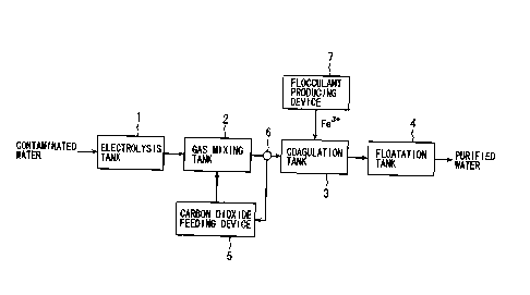
Fig. 1 is a block diagram showing the structure of an apparatus for
purification of water which is an embodiment of the present invention. 1n the
figure, the apparatus for purification of water of the present invention
mainly
comprises, in the order from the side where contaminated water is introduced,
an
electrolysis tank 1 for electrolyzing the contaminated water, a gas mixing
tank 2
for mixing carbon dioxide into the contaminated water electrolyzed, a
coagulation
tank 3 for mixing a flocculant into the contaminated water to coagulate
impurities
in the contaminated water, and a floatation tank 4 for floating the impurities
coagulated.
2o The electrolysis tank 1 has an electrode made of stainless steel, platinum,
carbon and the like, to which direct current is applied through a controller
(not
shown) for controlling the amount of electricity. A negative electrode is
covered
with a coating made of titanium, iridium, palladium, platinum, hafnium and the
like on the surface thereof in order to prevent itself from being dissolved by
the
applied electricity. 1n contaminated water introduced into the above
electrolysis
tank, the zeta potential of colloid particles contained in the contaminated
water
approaches zero by electrolysis. Here, the amount of electricity to be applied
to
CA 02389846 2002-05-O1
6
the electrode is controlled by the controller so that the zeta potential is a
weak
negative value.
A carbon dioxide feeding device 5, by which the amount of carbon dioxide
(C02) to be fed can be adjusted, is connected to the gas mixing tank 2. If the
pH
of the contaminated water electrolyzed by the electrolysis tank 1 is high,
carbon
dioxide fed from the carbon dioxide feeding device 5 is mixed. On the
downstream side of the gas mixing tank 2 and the upstream side of the
coagulation tank 3, disposed is a pH sensor 6 for detecting a hydrogen ion
concentration exponent (pH), and the output of the pH sensor 6 is inputted to
the
carbon dioxide feeding device S. Based on an inputted value (pH) of the pH
sensor 6, the carbon dioxide feeding device 5 automatically adjusts the amount
of
carbon dioxide to be fed into the gas mixing tank 2 and controls the pH of the
contaminated water detected by the pH sensor 6 to be from 5.3 to 8.
To the coagulation tank 3, connected is a flocculant producing device 7 for
obtaining fernc ions (Fe3+) as a flocculant by electrolyzing an iron electrode
to
cause fast oxidation. The flocculant producing device 7 will be explained
below
in detail referring to Figs. 2 and 3. Fig. 2 is a schematic view showing the
structure of the flocculant producing device 7, and Fig. 3 shows the structure
of an
iron ion reaction tank 13 wherein (a) is an inside plan view and (b) is an
inside
side view.
The flocculant producing device 7 comprises a high-concentration oxygen
water producing device 11 for producing oxygen-dissolved water, that is the
water
in which a high concentration oxygen is dissolved, an oxygen water control
tank
12 for controlling an oxygen concentration by mixing the oxygen-dissolved
water
produced into raw water which is the water to be treated, an iron ion reacting
tank
13 for eluting iron ions by electrolyzing an iron electrode and making the
contact
between the iron ions and oxygen in the oxygen-dissolved water to obtain a
CA 02389846 2002-05-O1
7
flocculant, and a control panel 14 as a control means for controlling the
amount of
electricity to be applied to the high-concentration oxygen water producing
device
11 and the iron electrode.
The high-concentration oxygen water producing device 11 makes oxygen
which is fed from an oxygen cylinder (not shown) dissolve in the water
introduced from the raw water to form small babbles having a diameter from
0.01
to 0.05 mm, thereby producing oxygen-dissolved water. The oxygen, which is
formed into fine babbles, can be efficiently dissolved in water, and the
high-concentration oxygen water producing device 11 provides oxygen-dissolved
to water having an oxygen concentration from 20 to 50 ppm, which is much
higher
than the general value of oxygen dissolution into water, that is from 10 to 15
ppm.
The oxygen water control tank 12 is a tank for mixing the
oxygen-dissolved water obtained by the high-concentration oxygen water
producing device 11 into raw water to control the oxygen concentration. The
oxygen-dissolved water of which oxygen concentration has been adjusted by the
oxygen water control tank 12 is fed into the iron ion reacting tank 13 of the
next
step.
As shown in Fig. 3, the iron ion reacting tank 13 is provided with a
plurality of electrode plates 16, as plate-like iron (Fe} electrodes, being
arranged
2o in a row in a direction perpendicular to the flowing direction of the
oxygen-dissolved water. The surface of each of the electrode plates 16 is
parallel to the flowing direction of the oxygen-dissolved water. The interval
between the adjacent electrode plates 16 is 10 mm. A voltage is applied to
each
of the electrode plates 16 so that each plate has the polarity opposite to the
polarity of the next plate.
In front of the electrode plates 16 in the flowing direction of the
oxygen-dissolved water, provided is an adjusting plate 17 for introducing the
CA 02389846 2002-05-O1
g
oxygen-dissolved water from the oxygen water control tank 12 into the areas
between the electrode plates 16 evenly. On the rear side of the electrode
plates
16 in the flowing direction of the oxygen-dissolved water, provided is a
punched
plate 18 having holes all over the surface uniformly. On the downstream side
of
the electrode plates 16, provided are an iron ion concentration sensor 19a for
detecting the Fe3+ concentration in the water and an oxygen concentration
sensor
19b for detecting the oxygen concentration in the water.
Based on the Fe3+ concentration detected by the iron ion concentration
sensor 19a, a control panel 14 controls the amount of the oxygen-dissolved
water
to be fed from the high-concentration oxygen water producing device 11 to the
oxygen water control tank 12, the oxygen concentration of the oxygen-dissolved
water produced by the high-concentration oxygen water producing device 11, the
amount of the direct current voltage (DCV) applied between the electrode
plates
16, and the amount of the oxygen-dissolved water introduced into the areas
between the electrode plates 16.
The amount of the oxygen-dissolved water fed from the
high-concentration oxygen water producing device 11 to the oxygen water
control
tank 12 is adjusted by controlling the opening degree of a solenoid operated
valve
20a which is disposed between the high-concentration oxygen water producing
2o device 11 and the oxygen water control tank 12. The oxygen concentration of
the oxygen-dissolved water produced by the high-concentration oxygen water
producing device 11 is adjusted by controlling the amount of oxygen fed into
the
high~oncentration oxygen water producing device 11 and the amount of raw
water supplied based on the oxygen concentration detected by the oxygen
concentration sensor 19b. The amount of the oxygen-dissolved water introduced
into the areas between the electrode plates 16 is adjusted by controlling the
opening degree of a solenoid operated valve 20b which is disposed between the
CA 02389846 2002-05-O1
9
oxygen water control tank 12 and the iron ion reacting tank 13.
In the flocculant producing device 7 having the above-described structure,
the oxygen-dissolved water having an oxygen concentration from 20 to 50 ppm
obtained by the high-concentration oxygen water producing device 11 is mixed
with the raw water in the oxygen water control tank 12 and, after adjustment
of
the oxygen concentration, flows into the iron ion reacting tank 13. The
oxygen-dissolved water in the iron ion reacting tank 13 is further introduced
into
the areas between the electrode plates 16 uniformly by the adjusting plate 17.
While the above operation is being conducted, in the iron ion reacting tank
13, Fe is eluted from the electrode plates 16 by the voltage applied to the
electrode
plates 16 to generate Fe2+ and Fe3+. Here, by supplying the oxygen-dissolved
water having an oxygen concentration from 20 to 50 ppm in which oxygen is
dissolved at a high concentration from the oxygen water control tank 12, Fe2+
is
oxidized at a high speed and completely oxidized into the form of more stable
Fe3+
In the flocculant producing device 7, it is also possible that, based on the
Fe3+ concentration on the downstream side of the electrode plates 16, the
control
panel 14 controls the amount of the oxygen-dissolved water to be fed, the
oxygen
concentration of the oxygen-dissolved water, and the amount of electricity
applied
or water supplied to the areas between the electrodes so that the Fe3+
concentration becomes maximum and further is maintained at the same level,
thereby obtaining Fe3+ with high efficiency.
By employing Fe, which is widely found in nature and inexpensive, as
electrodes, the costs for manufacturing and n~nning the apparatus can be held
to
be low. 1n addition, since dissolution of oxygen into water raises
conductivity of
water, the voltage necessary for electrolysis of the electrode plates 16 can
be
decreased. Therefore, it is possible to use a solar battery as a power source
of
CA 02389846 2002-05-O1
to
the apparatus, which means that the flocculant producing device 7 saves
energy.
Reverting to Fig. 1, in the coagulation tank 3, Fe3+ supplied from the
flocculant producing device 7 is mixed into the contaminated water fed from
the
gas mixing tank 2, thereby coagulating the colloid particles in the
contaminated
water to form flocs. The contaminated water fed from the gas mixing tank 2 has
been adjusted to have a pH in which the coagulation is caused most efficiently
by
Fe3+ (pH 5.3 - b.5) and has low zeta potential. Therefore, the amount of Fe3+
necessary for neutralizing the contaminated water can be small, which leads to
the
most efficient coagulation. In the floatation tank 4, the flocs formed in the
1o coagulation tank 3 are floated and separated by pressure floatation or the
like to
obtain purified water where the impurities have been removed.
In the apparatus for purification of water described above, the
contaminated water introduced into the electrolysis tank 1, as the zeta
potential of
the colloid particles contained in the contaminated water approaches plus-
minus
zero by electrolysis, has a weak negative value. The contaminated water which
contains the colloid particles having the low zeta potential is fed into the
gas
mixing tank 2 and mixed with carbon dioxide from the carbon dioxide feeding
device 5 to be adjusted to have a pH from 5.3 to 8.
In the coagulation tank 3 in the next step, the water is subjected to
coagulation by mixing Fe3+ supplied from the flocculant producing device 7.
Since the Fe3+ maintains the contaminated water to have a pH from 5.3 to 8,
which enables the most efficient coagulation, in addition to the low zeta
potential
of the colloid particles in the contaminated water introduced from the gas
mixing
tank 2, even a small amount of Fe3+ supplied from the flocculant producing
device
7 can realize sufficient coagulation. The flocs formed by the coagulation are
removed by the floatation tank 4 to discharge purified water.
The purified water obtained as above is not colored because Fe3+ is used as
CA 02389846 2002-05-O1
11
a flocculant, and has no harmful effect on human health if Fe3+ is discharged
without being consumed. Moreover, according to the present invention, since
the amount of Fe3+ necessary for purification can be small, an apparatus for
purification of water requiring a reduced amount of flocculant (Fe3+) with
extremely low running costs can be obtained.
The above-described embodiment, as shown in Fig. 1, is an example
wherein the electrolysis tank 1 is disposed before the coagulation tank 3.
However, the electrolysis tank 1 may be disposed after the coagulation tank 3
as
illustrated in Fig. 4.
1o In this case, the contaminated water to which a flocculant (Fe3+) has been
added in the coagulation tank 3 and which is then electrolyzed in the
electrolysis
tank 1 continues coagulation which started in the coagulation tank 3 even in
the
floatation tank 4. In the floatation tank 4, the flocs formed by coagulation
further grow to be large while floating. Therefore, if the electrolysis tank 1
is
disposed after the coagulation tank 3, thereby electrolyzing the contaminated
water after adding a flocculant (Fe3~, it is also possible to lower the zeta
potential
of the colloid particles in the contaminated water and to coagulate the
impurities
in the contaminated water with a reduced amount of flocculant and with high
efficiency as mentioned above.
2o In the above embodiments, Fe3+ produced by the flocculant producing
device 7 is used as a flocculant. On the other hand, it is also possible to
employ
other metal ions eluted by electrolyzing metal plates made of aluminum,
copper,
zinc or the like depending on the ingredients of impurities dissolved in
contaminated water. In this case, the zeta potential of the colloid particles
contained in the contaminated water is also lowered by the electrolysis tank 1
and
approaches plus-minus zero, which enables efficient coagulation of the
impurities
in the contaminated water with a reduced amount of these metal ions supplied.
CA 02389846 2002-05-O1
12
INDUSTRIAL APPLICABILITY
The apparatus and method for purification of water according to the
present invention can be used as an apparatus and method for purification of
water
for coagulating and removing impurities in contaminated water in rivers,
lakes,
ponds and the like by adding a flocculant to the contaminated water.