Note: Descriptions are shown in the official language in which they were submitted.
CA 02389944 2002-06-10
JJ-11 620CA
TITLE: Turbocharger Arrangement Structure for Personal
Watercraft
FIELD OF THE INVENTION
This invention relates to a turbocharger
arrangement structure for a personal watercraft.
BACKGROUND OF THE INVENTION
While the power source in widespread personal
watercrafts conventionally is a 2-cycle engine, it is
examined to use a 4-cycle engine for the power source in
order to cope with reduction of the pollution in recent
years.
However, since the output power of the 4-cycle
engine is lower than that of the 2-cycle engine of the
same total stroke volume, it is examined to incorporate
an engine with a turbocharger in order to make up the
power, and the assignee of the present application
proposed already a personal watercraft in which an engine
with a turbocharger is incorporated as Japanese Patent
Laid-Open No. 2001-140641.
In this personal watercraft, a 4-cycle engine 2
with a turbocharger 3 is incorporated in the inside of a
body 1 as shown in Figs. 11 and 12.
As shown also in Figs. 13 and 14, an exhaust
manifold 4 is provided on the left side of the 4-cycle
engine 2 in an advancing direction F of the body 1, and
an intake chamber 5 is provided on the right side of the
4-cycle engine 2.
Exhaust gas from an exhaust gas exit 4a of the
exhaust manifold 4 is introduced into a turbine portion
3T of the turbocharger 3, and compressed air from a
compressor portion 3C of the turbocharger 3 is supplied
into the intake chamber 5 described above through an
intercooler 6.
- 1 -
CA 02389944 2002-06-10
JJ-11 620CA
In such a personal watercraft as described
above, in order to make it difficult for water to enter a
body 1, it is necessary to form a hull 1a (refer to Fig.
11 ) and a deck 1b watertight and close up an opening of
the deck with a lid member (for example, a seat 7) to
form a body internal space 1c.
Meanwhile, in order to ensure intake of air
into an engine 2, it is necessary to introduce the
atmospheric air outside the body into the body internal
space 1c. In a personal watercraft wherein a
turbocharger is provided for an engine, when the
atmospheric air outside the body is introduced into the
body internal space 1c during running of the personal
watercraft, it is sometimes introduced in together with
water (for example, in the form of droplets). If the
turbocharger is directly wet with the water, then a
casing and so forth of the turbocharger whose temperature
is high are cooled suddenly and besides partially, which
gives rise to such a disadvantage that thermal fatigue is
liable to occur with the turbocharger.
The object of the present invention resides in
solution of such a problem as described above to provide
a turbocharger arrangement structure for a personal
watercraft which makes the turbocharger less liable to
become wet with water.
SUMMARY OF THE INVENTION
In order to attain the object described above,
according to the present invention, a turbocharger
arrangement structure for a personal watercraft is
characterized in that a hull and a deck of the personal
watercraft are formed watertight and an opening of the
deck is closed up with a lid member to form a body
internal space, and an intake duct for introducing the
atmospheric air outside the body is provided in the space
- 2 -
CA 02389944 2002-06-10
JJ-11 620CA
while an engine and a turbocharger connected to an
exhaust manifold of the engine are provided in the space
and the turbocharger is disposed higher than a body
internal opening of the intake duct.
According to an aspect of the invention, the
turbocharger arrangement structure for a personal
watercraft according to the above is characterized in
that a water jacket is formed in a casing of a turbine
portion of the turbocharger and an oil jacket is formed
in a bearing casing of the turbocharger, and cooling
water is supplied to the water jacket and cooling oil is
supplied to the oil jacket.
According to another aspect of the invention,
the turbocharger arrangement structure for a personal
watercraft according to the above is characterized in
that the cooling water to the water jacket is supplied by
a different turbocharger cooling water passage
independent of any other cooling water passage.
BRIEF DESCRIPTION OF THE DRAWINGS
Preferred embodiments of the invention are
shown in the drawings, wherein:
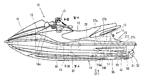
Fig. 1 is a schematic side elevational view
showing an example of a personal watercraft which uses an
embodiment of the turbocharger arrangement structure for
a personal watercraft according to the present invention.
Fig. 2 is a plan view of the personal watercraft
in Fig. 1.
Fig. 3 is a partial enlarged sectional view
(partly omitted sectional view) taken along line III-III
of Fig. 1.
Fig. 4 is a view principally showing an engine
20 and is a partial enlarged sectional view (partly
omitted sectional view) taken along line IV-IV of Fig. 1.
- 3 -
CA 02389944 2002-06-10
JJ-11 620CA
Fig. 5 is a right side elevational view of the engine 20.
Fig. 6 is a left side elevational view of the
engine 20.
Fig. 7 is a schematic perspective view of the
engine 20 as viewed from obliquely rearwardly.
Fig. 8 is a partial enlarged view of Fig. 5.
Fig. 9 is a view of a circulation route of oil.
Fig. 10 is a sectional view of a turbocharger
140.
Fig. 11 is an explanatory view of the prior
art.
Fig. 12 is an explanatory view of the prior
art.
Fig. 13 is an explanatory view of the prior
art.
Fig. 14 is an explanatory view of the prior
art.
DETAILED DESCRIPTION OF THE PREFERRED EMBODIMENTS
In the following, an embodiment of the present
invention is described with reference to the drawings.
Fig. 1 is a schematic side elevational view
showing an example of a personal watercraft which uses an
embodiment of the turbocharger arrangement structure for
a personal watercraft according to the present invention,
Fig. 2 is a plan view of the same, and Fig. 3 is a
partial enlarged sectional view (partly omitted sectional
view) taken along line III-III of Fig. 1.
As shown in the figures (principally in Fig.
1) , this personal watercraft 10 is a personal watercraft
of the saddle type, and a driver can sit on a seat 12 on
a body 11 and grip a steering handle 13 with a throttle
lever to steer the personal watercraft 10.
The body 11 has a floating body structure
wherein a hull 14 and a deck 15 are joined together such
- 4 -
CA 02389944 2002-06-10
JJ-11 620CA
that a space 16 is formed in the inside thereof. An
opening 15a (refer to Fig. 4) of the deck 15 is closed up
with the seat 12 serving as a lid member removably
mounted on the deck 15. In the space 16, an engine 20 is
mounted on the hull 14, and a jet pump (jet propulsion
pump) 30 as propulsion means which is driven by the
engine 20 is provided at a rear portion of the hull 14.
The jet pump 30 has a passage 33 extending from
an intake 17 open to the bottom to a jet outlet 31 and a
nozzle 32 open to the rear end of the body and an
impeller 34 disposed in the passage 33, and a shaft 35 of
the impeller 34 is connected to an output power shaft 21a
of the engine 20. Accordingly, if the impeller 34 is
driven to rotate by the engine 20, then water taken in
from the intake 17 is jetted from the nozzle 32 through
the jet outlet 31 so that the body 11 is propelled. The
driving speed of the engine 20, that is, the propelling
force by the jet pump 30, is operated by a pivoting
operation of a throttle lever 13a (refer to Fig. 2) of
the steering handle 13 described above. The nozzle 32 is
operatively associated with the steering handle 13 by an
operation wire not shown such that it is pivoted by an
operation of the steering handle 13, and the advancing
direction can be changed thereby.
It is to be noted that reference numeral 40
denotes a fuel tank, and 41 an accommodation chamber.
Fig. 4 is a view principally showing the engine
20 and is a partial enlarged sectional view (partly
omitted sectional view) taken along line IV-IV of Fig. 1,
Fig. 5 is a right side elevational view of the engine 20,
Fig. 6 is a left side elevational view of the engine 20,
Fig. 7 is a schematic perspective view of the engine 20
as viewed from obliquely rearwardly, and Fig. 8 is a
partial enlarged view of Fig. 5.
- 5 -
CA 02389944 2002-06-10
JJ-11 620CA
The engine 20 is a DOHC in-line four-cylinder
dry sump type 4-cycle engine and is disposed such that
the crankshaft 21a thereof extends in the forward and
backward direction of the body 11 as shown in Fig. 1.
As shown in Figs. 4 and 7, a surge tank (intake
chamber) 22 and an intercooler 23 communicated with an
intake port are connected and disposed on the left side
of the engine 20 with respect to the advancing direction
of the body 11, and an exhaust manifold 24 communicated
with an exhaust port 200 is connected and disposed on the
right side of the engine 20.
As shown in Figs. 6 and 7, a turbocharger
(turbocharger) 140 is disposed rearwardly of the engine
20, and an exhaust gas exit 240 of the exhaust manifold
24 is connected to a turbine portion 140T of the
turbocharger 140 while the intercooler 23 is connected to
a compressor portion 140C of the turbocharger 140 by a
pipe 26 (refer to Fig. 7). In Fig. 7, reference
characters 23a, 23b denote each a cooling water hose
connected to the intercooler 23.
It is to be noted that exhaust gas which has
rotated a turbine in the turbine portion 140T of the
turbocharger 140 passes, as shown in Figs. 1 and 2,
through an exhaust pipe 27a, a backflow preventing
chamber 27b for preventing a backflow of water (admission
of water into the turbocharger 140 and so forth) upon
capsize, a water muffler 27c and an drain pipe 27d and is
exhausted into a water stream produced by the jet pump
30.
Referring to Fig. 1, reference numerals 18, 19
denote each an intake duct for introducing the
atmospheric air outside the body 11 into the space 16 in
the body 11, and lower ends 18a, 19a of the intake ducts
18, 19 are provided lower than the turbocharger 140
described above in the body 11. In other words, the
- 6 -
CA 02389944 2002-06-10
JJ-11 620CA
turbocharger 140 is provided higher than the openings
18a, 19a of the intake ducts 18, 19 in the body. The
turbocharger 140 is provided substantially in the center
in the vertical direction in the space 16 of the body.
As shown in Figs. 4 to 7, an oil tank 50 and an
oil pump 80 are provided integrally on an extension line
of a crankshaft 21 at a front portion of the engine 20
(in the advancing direction of the body 11, and at a left
portion in Figs. 1 and 5 j . The oil pump 80 is provided
in the oil tank 50.
The oil tank 50 is formed from a tank body (one
divided case) 60 joined to a front face of the engine 20
and a cover (the other divided case) 70 joined to a front
face of the tank body 60.
As shown in Figs. 4 and 6, a water cooling type
oil cooler 90 is provided on the front face of the tank
body 60 in the oil tank 50, and an oil filter 100 is
provided at an upper portion of the oil tank 50.
As shown in Figs. 4, 5 and 8, the tank body 60
has a joining face 61 to the front face of the engine 20,
a joining face 62 to the cover 70, a mounting portion 63
for the oil pump 80, a mounting portion 64 for the water
cooling type oil cooler 90, a generally vertically
elongated oil accommodation portion 65 defined by
partition walls and outer walls which form the mounting
surfaces of them, an ACG 110, balancer shafts 114L, 1148,
and a cover portion 66 for a drive chamber of a starter
motor 120. Further, as shown in Fig. 6, the tank body 60
has a mounting portion 68 for the oil filter 100.
The tank body 60 is joined at the joining face
61 thereof described above to the front face of the
engine 20 and integrally secured to the front face of the
engine 20 by bolts not shown in such a manner that it
covers the elements described above. It is to be noted
that the tank body 60 is attached to the front face of
_ 7 _
CA 02389944 2002-06-10
JJ-11 620CA
the engine 20 after the oil pump 80 and the type oil
cooler 90 are attached thereto.
The cover 70 has a joining face 71 to the tank
body 60, a refilling opening 72 for oil, a holding
portion 73 for a relief valve 130, an accommodation
portion 74 (refer to Fig. 6) for the oil cooler 90, and
an oil accommodation portion 75 defined by outer walls
and a partition wall.
The oil pump 80 includes a first case 81 joined
to the tank body 60 described above, a second case 82
joined to the first case 81, a pump shaft 83 provided
such that it extends through the first and second cases,
inner and outer rotors 84 coupled to the pump shaft 83 in
the first case 81 described above for recovering oil, and
inner and outer rotors 85 coupled to the pump shaft 83 in
the second case 82 described above for supplying oil.
The inner and outer rotors 84 for recovering
oil cooperates with the first case 81 to form an oil
recovery pump, and the inner and outer rotors 85 for
supplying oil cooperates with the first and second cases
81, 82 to form an oil supply pump.
The oil pump 80 is attached to the front face
of the tank body 60 by means of bolts 88 after the
joining face of the first case 81 to the tank body 60 is
jointed to the mounting portion 63 on the front face of
the tank body 60 formed in the same shape as that of the
joining face.
After the oil pump 80 is attached to the tank
body 60 in this manner, a coupling 89 is secured to the
rear end of the pump shaft 83 from the rear face side of
the tank body 60 by means of bolts.
Accordingly, the tank body 60 is attached to
the front face of the engine 20 such that the coupling 89
is coupled to a coupling 111 provided at an end of an ACG
_ g _
CA 02389944 2002-06-10
JJ-11 620CA
shaft after the oil pump 80 and the coupling 89 are
attached and further the oil cooler 90 is attached.
The water cooling type oil cooler 90 is
attached to the front face side of the mounting portion
64 of the tank body 60 for the oil cooler 90.
As shown in Figs. 4 and 6, an upper hole 64a
and a lower hole 64b which are communicated with an oil
passage which is hereinafter described are formed in the
mounting portion 64 of the tank body 60.
Meanwhile, the oil cooler 90 has a plurality of
heat exchanging plates 91 through the inside of which oil
passes, an entrance pipe 92 for oil communicated at an
upper portion thereof with the inside of the plates 91,
and an exit pipe 93 for oil communicated at a lower
portion thereof with the inside of the plates 91.
Accordingly, the oil cooler 90 is attached to
the mounting portion 64 of the tank body 60 such that the
entrance pipe 92 thereof is connected to the upper hole
64a of the tank body 60 and the exit pipe 93 thereof is
connected to the lower hole 64b of the tank body 60.
As shown in Figs. 4 and 6, a cooling water
introduction pipe 97 which is communicated with a hole
64c open to the mounting portion 64 and introduces
cooling water into the accommodation portion 74 of the
oil cooler in the mounting portion 64 and the cover 70 is
provided on the tank body 60, and a discharge pipe 78 for
water is provided in the cover 70. A cooling water hole
97a from a cooling water output port 30a (refer to
Fig. 7) of the jet pump 30 is connected directly to the
introduction pipe 97 without intervention of any other
cooling object, and an drain pipe 23c is connected to the
discharge pipe 78 as shown in Fig. 6. Water from the
discharge pipe 78 is supplied into the water jacket of
the exhaust manifold 24 through the drain pipe 23c.
- 9 -
CA 02389944 2002-06-10
JJ-11 620CA
The cover 70 is joined to the front face of the
tank body 60 and secured by means of bolts not shown such
that a front end 132 of the relief valve 130 is held down
by the holding portion 73 described hereinabove after the
tank body 60, oil pump 80 and oil cooler 90 are attached
to the front face of the engine 20 in such a manner as
described above and then a rear end 131 of the relief
valve 130 is fitted into a hole 82a formed in the front
face of the second case 82 of the oil pump 80 as shown in
Figs. 5 and 8. The relief valve 130 is disposed
horizontally in this manner.
In the state wherein the tank body 60 and the
cover 70 are joined together, a single oil accommodation
section is formed from the oil accommodation portions 65,
75 of them.
Further, the oil filter 100 is attached to the
mounting portion 68 of the tank body 60 for the oil
filter 100.
It is to be noted that, in a state wherein the
engine 20 is incorporated in the body 11, the engine 20
and the oil filter 100 are opposed to the opening 15a of
the deck 15 as shown in Figs . 2 and 4 . The opening 15a
of the deck 15 is opened by removing the seat 12, which
is removably mounted on the body 11, from the body 11.
Such oil passages as described below are formed
in a state wherein the oil tank 50 (that is, the tank
body 60, the cover 70, and the oil pump 80, oil cooler
90, and relief valve 130 built in them) is mounted on the
front face of the engine 20 and the oil filter 100 is
mounted.
As shown in Figs. 5 and 8, an oil recovery
passage 51 is formed by the front face of the tank body
60 and the rear face of the first case 81 of the oil pump
80. The recovery passage 51 is formed from an oil
passage 51a formed on the tank body 60 side and an oil
- 10 -
CA 02389944 2002-06-10
JJ-11 620CA
passage 51b formed on the first case 81 side of the oil
pump 80 in an opposing relationship to the oil passage
51a.
A lower end 51c of the oil recovery passage 51
is communicated with an oil pan 28 of the engine 20
through a pipe 52, and an upper end 51d of the oil
recovery passage 51 is communicated with a recovered oil
inlet port 81i formed in the first case 81 of the oil
pump 80.
Similarly, a discharge passage 53 for recovered
oil is formed by the front face of the tank body 60 and
the rear face of the first case 81 of the oil pump 80.
The discharge passage 53 is formed from an oil passage
53a formed on the tank body 60 side and a recovered oil
discharge port 81o formed on the first case 81 side of
the oil pump 80 in an opposing relationship to the oil
passage 53a.
An upper end 53b of the discharge path 53 is
open to the inside of the oil tank 50 (that is, to the
inside of the oil accommodation section).
Meanwhile, an intake passage 54 and a discharge
passage 55 for supply oil are formed by the front face of
the first case 81 and the rear face of the second case 82
of the oil pump 80.
A lower end 54a of the intake passage 54 is
open to the inside of the oil tank 50 (that is, to the
inside of the oil accommodation section), and an upper
end 54b of the intake passage 54 is communicated with a
supply oil inlet port 82i of the oil supply pump. A
screen oil filter 54c is provided in the intake passage
54.
A lower end 55a of the discharge passage 55 is
communicated with a supply oil discharge port 820 of the
oil supply pump, and an upper end 55b of the discharge
passage 55 extends horizontally through an upper portion
- 11 -
.y
CA 02389944 2002-06-10
JJ-11 620CA
of the first case 81 and is communicated with a
horizontal hole 60a formed in the tank body 60. The
horizontal hole 60a is communicated with a vertical hole
60b formed in the tank body 60 similarly. An upper end
60c of the vertical hole 60b is open in the form of a
ring as viewed in plan to the mounting portion 68 of the
oil filter 100, and an oil inlet passage 101 of the oil
filter 100 is communicated with the opening 60c.
The mounting hole 82a for the relief valve 130
described hereinabove is open to the discharge passage
55, and the relief valve 130 is attached in such a manner
as described above to the mounting hole 82a.
A male thread is provided on an oil exit pipe
102 in the oil filter 100. The oil filter 100 is
attached to the mounting portion 68 of the tank body 60
by screwing the oil exit pipe 102 into a female threaded
hole 60d formed in the mounting portion 68 of the tank
body 60.
As shown in Fig. 6, a vertical hole 60e and a
horizontal hole 60f communicating with a lower end of the
vertical hole 60e are formed at a lower portion of the
female threaded hole 60d in the tank body 60. The
horizontal hole 60f is communicated with the entrance
pipe 92 of the oil cooler 90 through the upper hole 64a
of the mounting portion 64 of the oil cooler 90 described
hereinabove.
Meanwhile, an oil passage 60g communicating
with the lower hole 64b and an oil distributing passage
60h communicating with the passage 60g are formed in the
lower hole 64b of the tank body 60 described hereinabove
to which the exit pipe 93 of the oil cooler 90 is
connected. Further, a main gallery supply passage 60i
for supplying oil to a main gallery 20a (refer to Fig. 5)
of the engine 20, a left balancer supply passage 60j for
supplying oil to bearing portions of the left balancer
- 12 -
CA 02389944 2002-06-10
JJ-11 620CA
114L described hereinabove and a right balancer supply
passage 60k for supplying oil to bearing portions of the
right balancer 1148 are communicated with the oil
distributing passage 60h.
It is to be noted that one end of the oil
distributing passage 60h is closed up with a plug 60n
(refer to Fig. 6).
The route of oil supplied to the main gallery
20a of the engine 20 is such as shown in Fig. 9 (oil
circulation route diagram).
The route from the main gallery 20a is generally
divided into two.
The first route is a route along which oil is
supplied to bearing portions of the crankshaft 21 through
a route 20b (refer to Fig. 5), and the second route is a
route along which oil is supplied from a rear end 20a1 of
the main gallery 20a through a pipe 25a (refer to Fig. 7)
to cool and lubricate turbine bearings of the
turbocharger 140. The oil which has cooled and
lubricated the turbine bearings of the turbocharger 140
is recovered into the oil pan 28 through pipes 25b, 25c
(refer to Fig. 6).
The oil supplied to the bearing portions of the
crankshaft 21 further lubricates cam journal 20d portions
and lifter portions of a cylinder head through a route
20c and then returns to the oil pan 28 through a chain
chamber 20i.
Meanwhile, the oil supplied to the bearing
portions of the crankshaft 21 is further supplied to the
ACG, piston rear jet nozzles, connecting rod, cam chain
and starter needle and is recovered into the oil pan 28
through respective recovery passages. In Fig. 5,
reference character 20e denotes a jet nozzle for jetting
oil to the rear side of the piston to cool the piston,
20f a passage to the connecting rod portion, and 20g the
- 13 -
~ w
CA 02389944 2002-06-10
JJ-11 620CA
cam chain. Further, reference character return passage
20h denotes a returning passage for oil from an ACG
chamber 110c.
The oil in the ACG chamber returns to the oil
pan 28 through a return passage 20h therefor, and the oil
jetted to the rears of the pistons from jet nozzles 20e,
the oil supplied to the connecting rod and the oil
supplied to the starter needle return to the oil pan 28
individually through a crank chamber 20j.
As apparent from the foregoing description, a
general flow of oil is described below with reference
principally to Fig. 9.
The oil tank 50 -~ intake passage 54 --. screen
oil filter 54c -. oil pump (supply pump) 80 -~ discharge
passage 55 (and relief valve 130, horizontal hole 60a,
vertical hole 60b, ring-form opening 60c) -~ oil filter
100 -. vertical hole 60e, horizontal hole 60f ---. oil cooler
90 -~ oil passage 60g, oil distributing passage 60h -. main
gallery supply passage 60i, left balancer supply passage
60j, right balancer supply passage 60k ~ main gallery
20a, left balancer 114L, right balancer 1148.
Relief oil RO from the relief valve 130 returns
directly into the oil tank 50.
Oil supplied to the left balancer 114L, right
balancer 1148 returns to the oil pan 28 through the crank
chamber 20j.
Meanwhile, oil supplied to the various portions
described above from the main gallery 20a returns to the
oil pan 28 in such a manner as described above.
Then, the oil returned to the oil pan 28 is
recovered into the oil tank 50 through the pipe 52,
recovery passage 51, oil pump 80 (recovery pump) and
recovered oil discharge path 53, and is circulated by the
route described above from the intake passage 54.
- 14 -
CA 02389944 2002-06-10
JJ-11 620CA
Fig. 10 is a sectional view of the turbocharger
140.
As described above, the turbocharger 140
includes the turbine portion 140T and the compressor
portion 140C. The turbocharger 140 further includes a
bearing casing 141 which interconnects the turbine
portion 140T and the compressor portion 140C.
A bearing portion (accommodation chamber for a
bearing member) 142 is provided in the bearing casing
141, and a turbine shaft 143 is supported for rotation by
bearing members (ceramic ball bearings) 142a of the
bearing portion 142.
Turbine blades 143T are secured to the turbine
shaft 143 adjacent the turbine portion 140T, and
compressor blades 143C are secured to the turbine shaft
143 adjacent the compressor portion 140C.
Accordingly, within a process wherein exhaust
gas from the exhaust manifold 24 described hereinabove is
exhausted from an exhaust gas exit T2 to the exhaust pipe
27a (refer to Figs. 1 and 2) described hereinabove
through an exhaust passage T1 in the turbine portion
140T, the turbine shaft 143 is driven to rotate, and the
compressor blades 143C are driven to rotate so that air
from an intake air inlet port C1 communicating with an
intake box not shown is fed under pressure from the pipe
26 (refer to Fig. 7) to the intercooler 23 through an
intake passage C2 in the compressor portion 140C.
An oil entrance 144 is provided at an upper
portion of the bearing casing 141. The oil entrance 144
is communicated with the rear end portion 20a1 of the
main gallery 20a by the pipe 25a (refer to Fig. 7)
described hereinabove which services as an oil supply
passage. The pipe 25a is connected to the oil entrance
144 by an orifice bolt 145.
- 15 -
CA 02389944 2002-06-10
JJ-lI 620CA
An oil jacket 146 is formed in the inside of
the bearing casing 141, and the oil entrance 144
described above is communicated with the oil jacket 146
by an oil passage 144a. The bearing portion 142 is
communicated with the oil entrance 144 by a thin oil
passage 144b.
Accordingly, oil entering from the oil entrance
144 is supplied from the oil passage 144a to the oil
jacket 146 to cool the bearing casing 141, bearing
portion 142, turbine shaft 143 and members around them,
and is supplied from the oil passage 144b to the bearing
portion 142 to lubricate the bearing portion 142.
The oil of the oil jacket 146 is recovered into
the oil pan 28 from oil exits 146a and 146b of the oil
jacket 146 through the pipes 25b, 25c (refer to Fig. 6)
described hereinabove. Meanwhile, the oil of the bearing
portion 142 once enters the oil jacket 146 from an exit
142b of the bearing portion 142 and then is recovered
into the oil pan 28 from the oil exits 146a and 146b of
the oil jacket 146 described above through the pipes 25b,
25c (refer to Fig. 6) described hereinabove.
The pipe 25b is connected to the oil exit 146a,
and the pipe 25c is connected to the oil exit 146b.
The oil exits 146a, 146b are disposed higher
than an oil surface 01 (refer to Fig. 6) when the engine
stops.
Further, a one-way valve 147 is interposed in
each of the pipes 25b, 25c which serve as an oil
returning path.
As shown in Fig. 10, a water jacket T3 is
formed in the casing of the turbine portion 140T. An
entrance T4 for cooling water of the water jacket T3 is
connected to the cooling water output port 30a (refer to
Fig. 7) of the jet pump 30 described hereinabove by a
pipe 148a which forms a different turbocharger cooling
- 16 -
CA 02389944 2002-06-10
JJ-11 620CA
water passage independent of the other cooling water
passages. Further, an exit (not shown) of the water
jacket T3 for cooling water is connected to a water
jacket of the exhaust pipe 27a (refer to Figs. 1, 2) by a
pipe 148b shown in Fig. 7.
Accordingly, cooling water from the jet pump 30
is supplied to the water jacket T3 of the turbocharger
140 directly without intervention of any other cooling
object and cools the turbocharger 140, whereafter it
cools the exhaust pipe 27a. It is to be noted that the
water having cooled the exhaust pipe 27a further flows
into a water jacket of the backflow preventing chamber
27b to cool the backflow preventing chamber 27b and is
then jetted into the water muffler 27c, whereafter it is
discharged together with exhaust gas into water current
produced by the jet pump 30 through the exhaust and drain.
pipe 27d.
According to such a turbocharger arrangement
structure for a personal watercraft as described above,
the following operation and effects are obtained.
(a) The hull 14 and the deck 15 of the personal
watercraft are formed watertight and the opening 15a of
the deck 15 is closed up with the lid member 12 to form
the body internal space 16, and the intake ducts 18, 19
for introducing the atmospheric air outside the body are
provided in the space 16 and the engine 20 and the
turbocharger 140 connected to the exhaust manifold 24 of
the engine 20 are provided in the space 16 and besides
the turbocharger 140 is disposed higher than the body
internal openings 18a, 19a of the intake ducts 18, 19.
Therefore, when the atmospheric air outside the body is
introduced into the body internal space 16 through the
intake ducts 18, 19 during running of the personal
watercraft, even if it is introduced together with water
(for example, in the form of droplets), such a situation
- 17 -
CA 02389944 2002-06-10
JJ-11 620CA
that the turbocharger 140 becomes wet directly with the
water becomes less likely to occur.
Accordingly, such a situation that the casing
and so forth of the turbocharger 140 whose temperature is
high are cooled suddenly and besides partially becomes
less likely to occur, and thermal fatigue becomes less
likely to occur with the turbocharger 140. As a result,
the durability of the turbocharger 140 is augmented.
(b) The water jacket T3 is formed in the casing
of the turbine portion 140T of the turbocharger 140 and
the oil jacket 146 is formed in the bearing casing 141
for the turbocharger 140, and cooling water is supplied
to the water jacket T3 and cooling oil is supplied to the
oil jacket 146. Consequently, such a situation that the
temperature of the turbocharger 140 becomes excessively
high is eliminated.
Accordingly, when the atmospheric air outside
the body is introduced into the body internal space 16
through the intake ducts 18, 19 during running of the
personal watercraft, even if it is introduced together
with water (for example, in the form of droplets) and the
turbocharger 140 becomes wet directly with the water, the
temperature variation of the casing of the turbocharger
140 by the water is suppressed small.
As a result, thermal fatigue becomes less
likely to occur with the turbocharger 140, and the
durability of the turbocharger 140 is augmented with
certainty.
(c) Since cooling water for the water jacket T3
is supplied through the different turbocharger cooling
water passage 148a independent of the other cooling water
passages, the turbocharger 140 is cooled efficiently.
Accordingly, when the atmospheric air outside
the body is introduced into the body internal space 16
through the intake ducts 18, 19 during running of the
- 18 -
CA 02389944 2002-06-10
JJ-11 620CA
personal watercraft, even if it is introduced together
with water (for example, in the form of droplets) and the
turbocharger 140 becomes wet directly with the water, the
temperature variation of the casing of the turbocharger
140 by the water is suppressed smaller.
As a result, thermal fatigue becomes further
less likely to occur with the turbocharger 140, and the
durability of the turbocharger 140 is augmented with a
higher degree of certainty.
d) Since the cooling water from the
turbocharger cooling water passage 148a is first supplied
to the turbocharger 140 to cool the turbocharger 140 and
is then supplied to the exhaust system (exhaust pipe 27a,
backflow preventing chamber 27b, water muffler 27c,
exhaust and drain pipe 27d) provided on the downstream
with respect to the turbocharger 140 in the exhaust
system for the engine 20, the turbocharger 140 can be
cooled with cooling water in a state whose temperature is
lowest.
Accordingly, the turbocharger 140 can be cooled
further efficiently and sufficiently.
Further, also the exhaust system provided on
the downstream with respect to the turbocharger 140 can
be cooled.
(e) Since the cooling water having cooled the
turbocharger 140 is discharged to the outside of the
vessel 10 together with exhaust gas after it is supplied
to the exhaust pipe 27a provided on the downstream with
respect to the turbocharger 140 in the exhaust system,
the exhaust gas which has driven the turbocharger 140 is
further cooled in the exhaust pipe 27a.
In other words, since the exhaust gas is cooled
in the turbocharger 140 and the exhaust pipe 27a, the
exhaust gas energy can be reduced synergetically, and as
a result, the exhaust noise can be reduced.
- 19 -
CA 02389944 2002-06-10
JJ-11 620CA
(f) Since oil is supplied to the turbocharger
140 and the supplied oil is used to lubricate the bearing
portion 142 of the turbocharger 140 and supplied to the
oil jacket 146 formed in the bearing casing 141 to cool
the bearing casing 141, the turbocharger 140 is cooled
further better.
(g) Since the engine 20 is provided in the body
11 formed from the hull 14 and the deck 15 and the
turbocharger 140 is provided for the engine 20 and
besides the oil exits 146a, 146b of the turbocharger 140
are disposed higher than the oil surface 01 when the
engine stops, if the engine 20 is stopped (accordingly if
the operation of the oil pump 80 is stopped), then the
oil in the turbocharger 140 is discharged quickly from
the oil exits 146a, 146b.
If oil resides in the turbocharger 140 which
has a high temperature immediately after the engine
stops, then the resident oil is liable to be carbonized,
and as a result, there is a problem that the entire oil
which circulates in the engine 20 is liable to be
degraded. However, with the personal watercraft 10 in
which the engine with a turbocharger of the present
embodiment is incorporated, if the engine 20 stops, then
oil in the turbocharger 140 is discharged rapidly from
the oil exits 146a, 146b, the oil which may reside in the
turbocharger 140 after the engine stops can be minimized
to reduce the degradation of the entire oil.
(h) Since the engine 20 is a dry sump type
engine and the oil tank 50 is provided on an extension
line of the crankshaft thereof, the oil surface 01 when
the engine stops can be set low.
Accordingly, oil in the turbocharger 140 is
discharged further quickly from the oil exits 146a, 146b,
and as a result, the deterioration of the entire oil is
further reduced.
- 20 -
CA 02389944 2002-06-10
JJ-11 620CA
(i) Since the one-way valve 147 is interposed
in each of the oil returning passages 25b, 25c
communicated with the oil exits 146a, 146b of the
turbocharger 140, when the personal watercraft 10
capsizes, such a situation that oil reversely flows f rom
the oil pan 28 to the turbocharger 140 which is in a
high
temperature state and resides in the turbocharger 140 is
eliminated.
Accordingly, carbonization of oil can be
prevented with a higher degree of certainty, and
degradation of the entire oil can be reduced with a
higher degree of certainty.
(j) Since the turbocharger 140 and an end
portion of the main gallery 20a for oil provided in
parallel to the crankshaft 21 of the engine 20 are
communicated with each other by the oil supply pass age
25a, oil to the turbocharger 140 is supplied from the end
portion of the main gallery 20a to the turbocharger 140
directly through the oil supply passage 25a.
Accordingly, the time until oil is supplied to
the turbocharger 240 after the engine is started is
reduced, and quick and reliable operation of the
turbocharger 140 can be achieved.
(k) Since the oil pump 80 is provided on the
front side of the body 11 with respect to the engine 20
while the turbocharger 140 is provided on the rear s ide
of the body 11 and the turbocharger 140 and the rear end
portion of the main gallery 20a are communicated with
each other by the oil supply passage 25a, oil can be
supplied rapidly to the turbocharger 140 rearwardly of
the engine.
(1) Since oil supplied to the turbocharger 140
is used to lubricate the bearing portion 142 of the
turbocharger 140 and is supplied to the oil jacket 146
formed in the bearing casing 141 to cool the bear ing
- 21 -
CA 02389944 2002-06-10
JJ-11 620CA
casing 141, not only the bearing portion 142 of the
turbocharger 140 can be lubricated but also the bearing
casing 141 can be cooled.
Further, where lubrication of the bearing
portion 142 of the turbocharger 140 and cooling of the
bearing casing 141 are performed with oil supplied to the
turbocharger 140 in this manner, it is necessary to
quickly supply a greater amount of oil than ever to the
turbocharger 140. However, with the turbocharger cooling
structure 10 for a personal watercraft of the present
embodiment, since the oil to the turbocharger 140 is
supplied from the end portion of the main gallery 20a
directly to the turbocharger 140 through the oil supply
passage 25a, a greater amount of oil can be supplied
rapidly.
With the turbocharger arrangement structure for
a personal watercraft according to the present invention,
since the hull and the deck of the personal watercraft
are formed watertight and the opening of the deck is
closed up with the lid member to form the body internal
space, and the intake ducts for introducing the
atmospheric air outside the body are provided in the
space and the engine and the turbocharger connected to
the exhaust manifold of the engine are provided in the
space and besides the turbocharger is disposed higher
than the body internal openings of the intake ducts.
Therefore, when the atmospheric air outside the body is
introduced into the body internal space through the
intake ducts during running of the personal watercraft,
even if it is introduced together with water (for
example, in the form of droplets), such a situation that
the turbocharger becomes wet directly with the water
becomes less likely to occur.
Accordingly, such a situation that the casing
and so forth of the turbocharger whose temperature is
- 22 - -
CA 02389944 2002-06-10
JJ-11 620CA
high are cooled suddenly and besides partially becomes
less likely to occur, and thermal fatigue becomes less
likely to occur with the turbocharger. As a result, the
durability of the turbocharger is augmented.
With the turbocharger arrangement structure for
a personal watercraft according to an embodiment of the
invention, since, in the turbocharger arrangement
structure for a personal watercraft according to the
above, the water jacket is formed in the casing of the
turbine portion of the turbocharger and the oil jacket is
formed in the bearing casing for the turbocharger, and
cooling water is supplied to the water jacket and cooling
oil is supplied to the oil jacket. Consequently, such a
situation that the temperature of the turbocharger
becomes excessively high is eliminated.
Accordingly, when the atmospheric air outside
the body is introduced into the body internal space
through the intake ducts during running of the personal
watercraft, even if it is introduced together with water
(for example, in the form of droplets) and the
turbocharger becomes wet directly with the water, the
temperature variation of the casing of the turbocharger
by the water is suppressed small.
As a result, thermal fatigue becomes less
likely to occur with the turbocharger, and the durability
of the turbocharger is augmented with certainty.
With the turbocharger arrangement structure for
a personal watercraft according to another embodiment of
the invention, since, in the turbocharger arrangement
structure for a personal watercraft according to the
above, cooling water for the water jacket is supplied
through the different turbocharger cooling water passage
independent of the other cooling water passages, the
turbocharger is cooled efficiently.
- 23 -
CA 02389944 2002-06-10
JJ-12 620CA
Accordingly, when the atmospheric air outside
the body is introduced into the body internal space
through the intake ducts during running of the personal
watercraft, even if it is introduced together with water
(for example, in the form of droplets) and the
turbocharger becomes wet directly with the water, the
temperature variation of the casing of the turbocharger
by the water is suppressed smaller.
As a result, thermal fatigue becomes further
less likely to occur with the turbocharger, and the
durability of the turbocharger is augmented With a higher
degree of certainty.
Although various preferred embodiments of the
present invention have been described herein in detail,
it will be appreciated by those skilled in the art, that
variations may be made thereto without departing from the
spirit of the invention or the scope of the appended
claims.
- 24 -