Note: Descriptions are shown in the official language in which they were submitted.
I
CA 02390027 2002-05-06
WO 01/35480 PCT/DE00/03767
Description
Fuel cell installation
The invention relates to a fuel cell installation
having at least one fuel cell block which comprises a
number of fuel cells each having an anode and a
cathode, the anode adjoining an anode-gas chamber and
the cathode adjoining a cathode-gas chamber, and it
being possible for both the anode-gas chamber and the
cathode-gas chamber to be closed off in a gastight
manner.
It is known that, during electrolysis of water, the
water molecules are broken down by electric current
into hydrogen (H2) and oxygen (O2) . In a fuel cell,
inter alia this process takes place in reverse.
Electrochemical combining of hydrogen and oxygen to
form water forms electric current with a high
efficiency and, if pure hydrogen is used as fuel gas,
without the emission of pollutants and carbon dioxide
(C02). Even with a technical-grade fuel gas, for
example natural gas or coal gas and with air instead of
pure oxygen, in which case the air may additionally be
enriched with oxygen, a fuel cell generates
considerably fewer pollutants and less carbon dioxide
than other energy generators which operate with fossil
energy carriers.
Technical implementation of the principle of the fuel
cell has led to various solutions, specifically with
different types of electrolytes and with operating
temperatures of between 80°C and 1000°C. The fuel cells
are classified as low-temperature, medium-temperature
and high-temperature fuel cells, depending on their
operating temperature, and these categories can also be
CA 02390027 2002-05-06
w0 01/35480 - la - PCT/DE00/03767
distinguished from one another through different
technical embodiments.
i
CA 02390027 2002-05-06
WO 01/35480 - 2 - PCT/DE00/03767
An individual fuel cell supplies an operating voltage
of at most 1.1 volts. Therefore, a multiplicity of fuel
cells are stacked on top of one another and combined to
form a fuel cell block. In the specialist literature, a
block of this type is also known as a stack. Connecting
the fuel cells of the fuel cell block in series allows
the operating voltage of a fuel cell installation to be
several hundred volts.
A fuel cell comprises an electrolyte, to one side of
which an anode is fixed and to the other side of which
a cathode is fixed. The anode is adjoined by an
anode-gas chamber, through which the fuel gas can flow
past the anode when the fuel cell is operating. The
cathode is adjoined by a cathode-gas chamber, through
which oxygen or oxygen-containing gas can flow past the
cathode. The anode of a fuel cell is separated from the
cathode of an adjacent fuel cell by a separating
element. Depending on the type of fuel cell, this
separating element is designed, for example, as a
bipolar plate or as a cooling element.
When the fuel cell is operating, fuel gas flows through
the anode-gas chamber to the anode and
oxygen-containing gas flows through the cathode-gas
chamber to the cathode. The anode and the cathode are
produced, inter alia, from a porous material, so that
the fuel gas and the oxygen-containing gas can force
their way through the anode or the cathode in each case
to the electrolyte. Then, at the electrolyte, they
enter into the current-generating electrochemical
reaction with one another. When the uel cell
installation is switched off, the supply of gas to both
gas chambers is interrupted. However, a quantity of
residual gas remains in the fuel cells.
Since, in a fuel cell installation which has been
CA 02390027 2002-05-06
WO 01/35480 - 2a - PCT/DE00/03767
switched off, the fuel cells may be electrically
disconnected from the current consumer, an
electrochemical voltage may build up within the fuel
cell, and a further electrochemical
i
CA 02390027 2002-05-06
i~TO 01/35480 - 3 - PCT/DE00/03767
reaction between the hydrogen from the fuel gas and the
oxygen from the oxygen-containing gas does not occur.
In this state, however, both oxygen and hydrogen may
penetrate through the anode or cathode, which are in
each case produced from a porous material, and force
their way to the electrolyte. Depending on the
embodiment of the fuel cell, the oxygen may also pass
through the electrolyte. It then also penetrates
through the porous anode and therefore enters the
anode-gas chamber. Therefore, the residual gas which
remains in the fuel cells results in the formation of
oxide layers, which have an adverse effect on the
internal resistance of the cell, in the anode-gas
chamber. Corrosive phenomena may also occur, poisoning
the electrolyte and thereby shortening the service life
of the fuel cells. Both an increase in the cell
internal resistance and corrosion of components lead to
the cell voltage being reduced.
To solve this problem, it is disclosed in
DE 28 36 464 B2 that the supplies of gas to the fuel
cell installation can be designed in such a manner that
it is reliably ensured that the fuel-gas pressure which
is present in the fuel cells is always higher than the
pressure of the oxygen-containing gas. This effectively
prevents oxygen from passing into the anode-gas
chamber. A drawback of a fuel cell installation of this
type is that it requires pressure-control mechanisms,
which are not only expensive but also cannot reliably
ensure that no oxygen will reach the anode-gas chamber
even in the event of the fuel cell installation
malfunctioning.
The abstract of JP 06 333586, in "Patent Abstracts of
Japan", proposes that, when the fuel cell installation
is switched off, initially the supply of oxygen-
m
, CA 02390027 2002-05-06
WO 01/35480 - 3a - PCT/DE00/03767
containing gas is interrupted, and then an electrical
load is used to ensure that the electrochemical
reaction at the electrolyte is not interrupted, and
that the supply of fuel gas is interrupted only when
the cell voltage falls. In this case, the fall in the
cell voltage is an indication that virtually
CA 02390027 2002-05-06
TnTO 01/35480 - 4 - PCT/DE00/03767
all the oxygen has been consumed. Then, substantially
only fuel gas remains in the fuel cells . A drawback is
that a fuel cell installation of this type requires the
gas valves to be controlled, which is likewise complex
and susceptible to malfunctioning.
In WO 97/48143 A1 it is proposed that, in order for the
fuel cell installation to be switched off, in a first
step the supply of the oxygen-containing gas be
interrupted, the oxygen partial pressure in. the fuel
cells be measured, and at a predetermined, low oxygen
partial pressure, the supply of fuel gas also be
interrupted. In this method too, an electric load is
used to maintain the electrochemical reaction and
therefore the oxygen consumption. If the oxygen partial
pressure in the cathode-gas chamber is low enough, the
residual oxygen which remains in the fuel cells, while
the electrochemical reaction with the hydrogen from the
fuel gas remaining in the fuel cells is maintained, can
react completely. This ensures that there is no longer
any residual oxygen in the fuel cells. However, this
method too disadvantageously requires control of the
gas valves, which is complex and not sufficiently
resistant to malfunctions.
It is an object of the present invention to provide a
fuel cell installation in which premature aging of the
fuel cells caused by residual oxygen remaining in the
fuel cells is avoided in a simple way.
This object is achieved by a fuel cell installation of
the type described in the introduction in which,
according to the invention, the volume of the anode-gas
chamber in the closed state is at least twice as great
as the volume of the cathode-gas chamber in the closed
state.
If a fuel cell installation of this type is operated,
CA 02390027 2002-05-06
WO 01/35480 - 4a - PCT/DE00/03767
for example, with pure hydrogen as fuel gas and pure
oxygen,
i
CA 02390027 2002-05-06
WO 01/35480 - 5 - PCT/DE00/03767
in volume terms at least twice as much hydrogen remains
in the anode-gas chamber as oxygen in the cathode-gas
chamber after the fuel cell installation has been
switched off. If the supply of the two operating gases
is interrupted simultaneously, and if the
electrochemical reaction is maintained by means of an
electrical load, the hydrogen from the anode-gas
chamber can react with the oxygen from the cathode-gas
chamber along the electrolyte. During the
electrochemical reaction between hydrogen and oxygen to
form water, twice as much hydrogen as oxygen is
consumed. Since, on account of the size of the gas
chambers, there is more than twice as much hydrogen in
the anode-gas chamber as oxygen in the cathode-gas
chamber, the oxygen is completely consumed, so that, a
short time after the fuel cell installation has been
switched off, only hydrogen remains in the fuel cells.
This effectively prevents oxidation of components of
the fuel cells without the fuel cell installation
having to be equipped with a control mechanism to
switch off the fuel cell installation.
The term anode-gas chamber is understood as meaning a
gas chamber which comprises the following gas chambers:
a) the anode-gas reaction chamber of at least one
anode, and
b) the gas chamber which is formed by the passages
and lines connected to the anode-gas chamber, the
passages and lines leading from the anode-gas
chamber to a closure, which is used to close off
the anode-gas chamber.
The term anode-gas reaction chamber of an anode is
understood as meaning the gas chamber which directly
adjoins the anode. Within this anode-gas reaction
chamber, the fuel gas can flow freely over the surface
of the porous anode in order then to penetrate into the
i
CA 02390027 2002-05-06
WO 01/35480 - 5a - PCT/DE00/03767
anode. Feed and discharge lines for the fuel gas are
connected to the anode-gas reaction chamber. These
lines may be formed, for example, as flexible tubes or
lines. However, they may also be designed in the form
of passages within the fuel cell block.
. CA 02390027 2002-05-06
WO 01/35480 - 6 - PCT/DE00/03767
In a similar way to the anode-gas chamber, the
cathode-gas chamber comprises the cathode-gas reaction
chamber of at least one cathode and the gas chamber
which is formed by the passages or lines connected to
the cathode-gas chamber.
The anode-gas chamber and the cathode-gas chamber can
be closed off in a gastight manner, for example by
means of shut-off valves which can be closed
simultaneously. This is easily ensured, by way of
example, by the shut-off valves which delimit the gas
volume of the gas chambers being connected to a common
circuit or being simultaneously connected by a control
unit.
The fuel cell installation is advantageously designed
for oxygen operation. During operation, an installation
of this type is fed with oxygen as cathode gas. When
pure hydrogen is fed as fuel gas into the fuel cell
installation it is ensured, as described above, that
after the fuel cell installation has been switched off
no residual oxygen remains within the fuel cells.
However, the fuel cell installation may equally be
designed for operation with oxygen-containing gas, for
example air. Furthermore, the fuel cell installations
may be designed both for operation with air and
alternatively also for operation with oxygen. In the
case of a fuel cell installation which is operated with
air and to which pure hydrogen is supplied as fuel gas
during operation, the problem described above does not
necessarily occur, since only approximately 20~ of air
is oxygen. However, a fuel cell installation according
to the invention which is designed for operation with
air allows operation with gas ballast without there
being any risk of the fuel cells being oxidized after
the fuel cell installation has been switched off. When
i
CA 02390027 2002-05-06
WO 01/35480 - 6a - PCT/DE00/03767
a fuel cell installation is operated with gas ballast,
fractions of the anode exhaust gas or all the anode
offgas are returned to the fuel cells as fuel gas. As a
result, there is no accumulation of
~i
CA 02390027 2002-05-06
WO 01/35480 - 7 - PCT/DE00/03767
combustible gas, in particular inert gases, in the
anode-gas chamber. This reduces the concentration of
the hydrogen in the fuel gas in the anode-gas chamber.
However, when the fuel cell installation is switched
off, despite the possibly low concentration of hydrogen
in the fuel gas, it is always still ensured that, after
the fuel cell installation has been switched off and
the supply of operating gases has been interrupted,
sufficient hydrogen still remains in the anode-gas
chamber to completely convert the oxygen from the
cathode-gas chamber into an electrochemical reaction.
In an advantageous configuration of the invention, a
number of anodes each adjoin an anode-gas chamber, and
a number of cathodes each adjoin a cathode-gas chamber.
The two numbers do not have to be identical. An
anode-gas chamber of this type is formed, for example,
by the number of anode-gas reaction chambers which
adjoin the anodes, the lines and/or passages situated
between the anode-gas reaction chambers and the gas
feed and discharge lines leading to the shut-off
valves. A combination of a number of anode-gas reaction
chambers of this type to form one anode-gas chamber has
the advantage that it is not necessary for it to be
possible to shut off each anode-gas reaction chamber
separately, for example by means of shut-off valves. In
this configuration of the invention, one fuel cell
block of a fuel cell installation may be assigned a
plurality of anode-gas chambers and cathode-gas
chambers. This may be the case, for example, if fuel
gas or oxygen-containing gas is fed through the fuel
cell block in cascaded form.
In an advantageous refinement of the invention, the
fuel cell block is assigned only one anode-gas chamber
and one cathode-gas chamber. An anode-gas chamber or
cathode-gas chamber of this type comprises the gas
a'~
CA 02390027 2002-05-06
WO 01/35480 - 7a - PCT/DE00/03767
reaction chambers of all anodes or cathodes of the fuel
cell block. In a fuel cell installation of this type,
to close off all the gas chambers within the fuel cells
of the fuel cell block in a gastight manner, in each
case only one valve is required in the feed and
discharge lines
CA 02390027 2002-05-06
WO 01/35480 - 8 - PCT/DE00/03767
for the fuel gas and the oxygen-containing gas to and
from the fuel cell block.
The anode-gas chamber or the cathode-gas chamber
advantageously comprises the gas chamber of a gas
vessel. Alternatively, the anode-gas chamber and the
cathode-gas chamber in each case comprise the gas
chamber of a gas vessel. The gas vessel is designed in
such a way that the gas chamber which it surrounds -
together with the other gas chambers assigned to the
anode-gas chamber or cathode-gas chamber - creates the
desired volumetric ratio of anode-gas chamber to
cathode-gas chamber. In this configuration of the
invention, the anode-gas reaction chambers o.f the fuel
cell block may be of structurally identical design to
the cathode-gas reaction chambers of the fuel cell
block. This allows the fuel cell block to be designed
with the same geometry as has hitherto been customary,
namely with geometrically identical anode-gas reaction
chambers and cathode-gas reaction chambers. A gas
vessel is merely added to the anode-gas chamber or the
cathode-gas chamber. Depending on the size of the gas
vessel, the volumetric ratio between anode-gas chamber
and cathode-gas chamber may be set in such a manner
that the fuel cell installation can be switched off as
a function of the fuel gas or oxygen-containing gas
supplied without there being any risk of corrosion. In
this case, the gas vessel may be arranged outside the
fuel cell block or may be integrated in the fuel cell
block. The gas vessel used may, for example, be what is
known as an "air chamber". An "air chamber" of this
type is used in some fuel cell installations to reduce
pressure surges.
In an expedient configuration of the invention, the gas
vessel is a hydrogen separator or an oxygen separator.
A separator of this type is often used in fuel cell
CA 02390027 2002-05-06
WO 01/35480 - 8a - PCT/DE00/03767
installations. In this configuration of the invention,
there is no need for a component which is produced
specifically to set the desired volumetric ratio. This
makes a design of this type particularly simple and
inexpensive to implement.
CA 02390027 2002-05-06
WO 01/35480 - 9 - PCT/DE00/03767
In a further advantageous configuration of the
invention, a cooling element is arranged between the
anode of a first fuel cell and the cathode of an
adjacent fuel cell, in such a manner that the gas
chamber between anode and cooling element is
significantly larger than the gas chamber between
cathode and cooling element. In the case of a
low-temperature fuel cell, a cooling element is used to
dissipate the heat generated during the electrochemical
reaction from the fuel cell. It is generally arranged
between anode and cathode, specifically in such a
manner that the anode-gas reaction chamber is formed
between the cooling element and the anode and the
cathode-gas reaction chamber is formed between the
cooling element and the cathode. Hitherto, a cooling
element of this type has been arranged symmetrically
between cathode and anode, so that the anode-gas
reaction chamber and the cathode-gas reaction chamber
are designed to be of the same size. If the cooling
element is arranged asymmetrically between the cathode
and the anode, the anode-gas reaction chamber and the
cathode-gas reaction chamber are designed to be of
different sizes. In this way, the arrangement of the
cooling element can be used to set the volumetric ratio
between anode-gas chamber and cathode-gas chamber in
the desired way without a further component
additionally having to be added to the fuel cell
installation for this purpose.
The cooling element (24) is expediently designed
asymmetrically with regard to the size of the gas
chambers. This asymmetric design may, for example,
consist in the cooling element having a form which is
of different shape or different height on its side
which faces the anode from its side which faces the
cathode. The shape or form of the two sides of the
cooling element decisively influences the size of the
anode-gas
i
CA 02390027 2002-05-06
WO 01/35480 - 9a - PCT/DE00/03767
or cathode-gas reaction chamber. Therefore, given
different shapes of the two sides of the cooling
element, the size of the anode-gas reaction chamber
differs from that of the cathode-gas reaction chamber.
As a result, it is particularly easy to
CA 02390027 2002-05-06
w0 01/35480 - 10 - PCT/DE00/03767
set the volumetric ratio between anode-gas chamber and
cathode-gas chamber in a predetermined way.
A further advantage can be achieved by the fuel cells
being PEM fuel cells . PEM fuel cells are operated at a
low operating temperature of approximately 80°C, have a
favorable overload behavior and a long service life.
Moreover, they behave favorably in the event of rapid
load changes and can be operated with air and also with
pure oxygen. All these properties make PEM fuel cells
particularly suitable for use in the mobile sector, for
example for driving vehicles of very diverse kind.
A further preferred embodiment of the invention can be
achieved by the invention being modified in such a way
that the volume of the anode-gas chamber is at least
1.5 times as great as the volume of the cathode-gas
chamber. Depending on the operating gas or
oxygen-containing gas with which the fuel cell
installation is operated, it may be sufficient, to
allow the fuel cell installation to be switched off
without risks, for the anode-gas chamber to be only at
least 1.5 times as large as the cathode-gas chamber. In
this configuration of the invention, the fuel cell
block may be designed to be slightly' smaller than with
a volumetric ratio of 1:2.
Exemplary embodiments of the invention are explained
with reference to three figures, in which:
FIG. 1 shows a section through a fuel cell having an
anode-gas chamber and a cathode-gas chamber;
FIG. 2 shows a section through a plurality of fuel
cells, each having a cooling element,
FIG. 3 diagrammatically depicts the supply and removal
of operating gas to and from fuel cells.
CA 02390027 2002-05-06
- 11 -
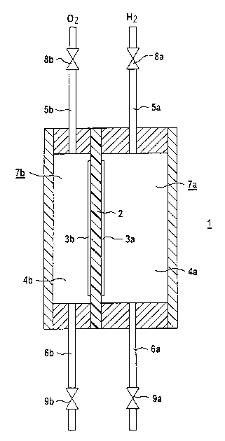
FIG. 1 shows a fuel cell 1 which comprises a flat
electrolyte 2 and electrodes which are fixed to it,
namely the anode 3a and the cathode 3b. The anode-gas
reaction chamber 4a assigned to the anode 3a joins the
anode 3a. The cathode-gas reaction chamber 4b assigned
to the cathode 3b adjoins the cathode 3b. The fuel
cell 1, which is designed for operation with pure
oxygen 02 and pure hydrogen H2, is supplied with
hydrogen H2 through the fuel-gas feedline 5a and with
oxygen 02 through the oxygen feedline 5b. When the fuel
cell 1 is operating, fuel gas flows through the
fuel-gas feedline 5a into the anode-gas reaction
chamber 4a, where it can pass along the anode 3a and
react at the electrolyte 2. The fuel which is not
consumed during this process emerges from the anode-gas
reaction chamber 4a through the fuel-gas discharge line
6a and is removed from the fuel cell. In a similar way,
the oxygen passes through the oxygen feedline 5b into
the cathode-gas reaction chamber 4b, can penetrate
through the cathode 3b to the electrolyte and react at
the electrolyte. The oxygen which is not. consumed
during this process is guided out of the cathode-gas
reaction chamber 4b through the oxygen discharge line
6b and is removed from the fuel cell 1.
The anode-gas reaction chamber 4a is part of the
anode-gas chamber 7a, the gas volume of which is
composed of the gas volume of the anode-gas reaction
chamber 4a and the gas volume of the fuel-gas feedline
5a and of the fuel-gas discharge line 6a. The volume of
the anode-gas chamber 7a is delimited by a fuel-gas
feedline valve 8a and a fuel-gas discharge line
valve 9a. The volume of the anode-gas chamber 7a is
approximately 2~ times as great as the volume of the
cathode-gas chamber 7b, which is composed of the total
of the volume of the cathode-gas reaction chamber 4b
and the volumes of the oxygen feed and discharge
lines 5b and 6b, respectively. The volume of the
i
CA 02390027 2002-05-06
WO 01/35480 - lla - PCT/DE00/03767
cathode-gas chamber 7b is delimited by an oxygen
feedline valve 8b and an oxygen discharge line
valve 9b.
/I
CA 02390027 2002-05-06
WO 01/35480 - 12 - PCT/DE00/03767
FIG. 2 shows an excerpt of a fuel cell block 20. Three
electrolytes 22, as well as the anodes 23a and cathodes
23b which bear fixedly against the electrolyte, can be
seen in this excerpt. A cooling element 24 is in each
case arranged between the anode 23a of one fuel cell
and the cathode 23b of an adjacent fuel cell. The
cooling element 24 comprises two plates, namely the
anode plate 24a and the cathode plate 24b. The anode
23a and the anode plate 24a of an adjacent cooling
element 24 delimit the anode-gas reaction chamber 25a
of a fuel cell. The cathode 23b of a fuel cell,
together with the cathode plate 24b of the adjacent
cooling element 24, delimits the cathode-gas reaction
chamber 25b of the fuel cell. The anode-gas reaction
chambers 25a and cathode-gas reaction chambers 25b of
the fuel cell block 20 are also delimited by a seal 26,
which is partially illustrated in FIG. 2. Feed and
discharge lines for fuel gas and oxygen-containing gas
are incorporated in this seal 26, but are not
illustrated in FIG. 2. The volume of the anode-gas
reaction chambers 25a and of the cathode-gas reaction
chambers 25b are decisively determined by the shape of
the cooling elements 24. The anode plates 24a and the
cathode plates 24b, between which there is in each case
one cooling-water chamber 24c, are shaped in such a way
that the volume of the anode-gas reaction chambers 25a
is approximately twice as great as the volume of the
cathode-gas reaction chambers 25b. In each case a
number of anode-gas reaction chambers and cathode-gas
reaction chambers are combined to form one anode-gas
chamber or one cathode-gas chamber.
The asymmetric shape of the cooling elements 24 ensures
in a simple way that, when the fuel cell installation
is switched off, approximately twice as much fuel gas
remains in the anode-gas chamber as oxygen-containing
gas in the cathode-gas chamber. In this exemplary
CA 02390027 2002-05-06
WO 01/35480 - 12a - PCT/DE00/03767
embodiment, the asymmetry is achieved by the different
shape of anode plate 24a and cathode plate 24b of the
cooling elements. This measure, which is easy to
implement in design terms,
CA 02390027 2002-05-06
WO 01/35480 - 13 - PCT/DE00/03767
ensures that when the fuel cell installation is
switched off, there is no risk of corrosion to
components of the fuel cells. This applies in
particular to a fuel cell installation which is
operated with an operating gas in which the oxygen
partial pressure of the oxygen-containing gas is no
greater or is only slightly greater than the hydrogen
partial pressure of the fuel gas.
FIG. 3 diagrammatically depicts the structure of a fuel
cell installation 41. The fuel cell installation 41
composes a fuel cell block 42 which, for its part,
contains a multiplicity of fuel cells. Each of these
fuel cells comprises an electrolyte 43 and an anode 44a
and a cathode 44b. The anodes 44a of all the fuel cells
in each case adjoin an anode-gas reaction chamber 45a.
The cathodes 44b of all the fuel cells in each case
adjoin a cathode-gas reaction chamber 45b. The
anode-gas reaction chamber 45a of each fuel cell is
delimited by the anode 44a, a separating element 46,
which may be designed, for example, as a bipolar plate
or as a cooling unit, and a seal 47 arranged around the
fuel cells. The fuel cells are supplied with fuel
through a fuel feedline 48a. They are supplied with
oxygen-containing gas through the oxygen feedline 48b.
The operating gases fuel and oxygen-containing gas flow
through the anode-gas reaction chamber 45a and
cathode-gas reaction chamber 45b, respectively, some of
the operating gases being consumed during the
electrochemical reaction at the electrolyte 43. The
unconsumed part of the fuel gas is guided out of the
fuel cells through a fuel discharge line 49a. It then
passes into a gas vessel 50a which is designed as an
oxygen separator. The oxygen-containing gas which is
not consumed in the electrochemical reaction is guided
out of the fuel cells through an oxygen discharge
line 49b and passed into a gas vessel 50b, which is
designed as an oxygen separator.
CA 02390027 2002-05-06
- 14 -
In this exemplary embodiment, the fuel cell block 42
has only a single anode-gas chamber 51a. The volume of
the anode-gas chamber 51a is composed of the volumes of
all the anode-gas reaction chambers 45a of the fuel
cell block and of the fuel-gas feedline 48a, the
fuel-gas discharge line 49a and the volume surrounded
by the gas vessel 50a. The valves 52 can be used to
close off both the anode-gas chamber and the
cathode-gas chamber in a gastight manner. The volume of
the anode-gas chamber 51a is approximately three times
as large as the volume of the cathode-gas chamber 51b,
which is designed in a similar manner to the anode-gas
chamber 51a. The difference in volume between the two
gas chambers is produced by the different size of the
gas vessels 50a and 50b. The gas vessel 50a, which is
designed as a hydrogen separator, is significantly
larger than the gas vessel 50b designed as an oxygen
separator.
When the fuel cell installation is switched off, the
anode-gas chamber 51a and the cathode-gas chamber 51b
are closed off in a gastight manner by the valves 52
which can be closed simultaneously. The electrochemical
reaction along the electrolyte 43 of the fuel cell
block is maintained by an electrical load, ensuring
that it is impossible for an excessively high voltage
to build up in the fuel cells. As a result, the
hydrogen in the anode-gas chamber 51a and the oxygen in
the cathode-gas chamber 51b are consumed until there is
virtually no more oxygen left in the cathode-gas
chamber 51b. This ensures that, after the fuel cell
installation has been switched off, there is virtually
no oxygen left in the fuel cells of the fuel cell
installation, and there is no risk of oxidation causing
premature aging of the components of the fuel cells.