Language selection

Search

Patent 2390208 Summary

Third-party information liability

Some of the information on this Web page has been provided by external sources. The Government of Canada is not responsible for the accuracy, reliability or currency of the information supplied by external sources. Users wishing to rely upon this information should consult directly with the source of the information. Content provided by external sources is not subject to official languages, privacy and accessibility requirements.

Claims and Abstract availability

Any discrepancies in the text and image of the Claims and Abstract are due to differing posting times. Text of the Claims and Abstract are posted:

  • At the time the application is open to public inspection;
  • At the time of issue of the patent (grant).
(12) Patent: (11) CA 2390208
(54) English Title: TERMINAL CONNECTION STRUCTURE OF A RESOLVER STATOR COIL
(54) French Title: STRUCTURE DE RACCORDEMENT TERMINAL D'UN ENROULEMENT STATORIQUE DE RESOLVEUR
Status: Deemed expired
Bibliographic Data
(51) International Patent Classification (IPC):
  • H02K 24/00 (2006.01)
  • H01R 4/02 (2006.01)
  • H02K 3/00 (2006.01)
  • H02K 3/50 (2006.01)
  • H02K 3/52 (2006.01)
(72) Inventors :
  • MIMURA, HISASHI (Japan)
(73) Owners :
  • TAMAGAWA SEIKI KABUSHIKI KAISHA (Not Available)
(71) Applicants :
  • TAMAGAWA SEIKI KABUSHIKI KAISHA (Japan)
(74) Agent: MARKS & CLERK
(74) Associate agent:
(45) Issued: 2006-04-04
(22) Filed Date: 2002-07-02
(41) Open to Public Inspection: 2003-01-05
Examination requested: 2002-07-02
Availability of licence: N/A
(25) Language of filing: English

Patent Cooperation Treaty (PCT): No

(30) Application Priority Data:
Application No. Country/Territory Date
2001-205257 Japan 2001-07-05

Abstracts

English Abstract


Disclosed is a terminal connection structure of a resolver
stator coil in which a part of the end portion of the stator coil
is left as a free end portion which is free with respect to the
terminals, whereby external impact is absorbed, and rupture of the
stator coil is prevented, thereby achieving an improvement in
reliability. An end portion (30) of a stator coil (1) is wound
around terminals (4) to form a winding connection portion (5), and
a part of the end portion (3) is left as a free end portion (30)
which is not integrally connected to the terminals (4) by soldering
or fusing, whereby a spring function is obtained.


Claims

Note: Claims are shown in the official language in which they were submitted.


The embodiments of the invention in which an exclusive
property or privilege is claimed are defined as follows:

1. A terminal connection structure of a resolver stator
coil comprising a resolver stator coil wound around each
magentic pole tooth of said stator through the
intermediation of annular insulation caps, and a winding
and connection portion formed by winding an end portion of
said stator coil around a plurality of terminals provided
in a peripheral edge portion of said insulation cap, said
stator coil and said terminals being integrally connected
to said winding and connection portion by one of soldering
and fusing,
wherein a part of said end portion wound around said
winding connection portion is left as a free end portion
which is not integrally connected to said terminals by said
soldering or fusing, and
further wherein said terminals are disposed so that in
cross-section a peripheral portion of at least one of the
terminals extends along or parallel to a radial direction
of said resolver stator.

2. A terminal connection structure of a resolver stator
coil according to Claim 1, wherein said free end portion is
wound at least one time around said terminals.

3. A terminal connection structure of a resolver stator
coil according to Claim 1, wherein said free end portion is
wound at least a plurality of times around said terminals.

4. A terminal connection structure of a resolver stator
coil according to any one of Claims 1 through 3, wherein
said free end portion has a spring function and a sagging
function.

8


5. A terminal connection structure of a resolver stator
coil comprising a resolver stator, a stator coil wound
around each magnetic pole tooth of said stator through the
intermediation of annular insulation caps, and a winding
and connection portion formed by winding an end portion of
said stator coil around a plurality of terminals provided
in a peripheral edge portion of said insulation cap, said
stator coil and said terminals being integrally connected
to said winding and connection portion by one of soldering
and fusing, and
means for preventing breakage of said stator coil, said
means for preventing breakage being disposed in said end
portion and adjacent to said stator coil,
wherein said terminals are disposed so that in cross-
section a peripheral portion of at least one of the
terminals extends along or parallel to a radial direction
of said resolver stator.

6. A terminal connection structure of a resolver stator
coil according to any one of Claims 1 to 5, wherein said at
least one of the terminals is rectangular in cross-section
and is disposed so that a long side of the rectangle
extends along or parallel to the radial direction of said
resolver stator.

9

Description

Note: Descriptions are shown in the official language in which they were submitted.


i
CA 02390208 2002-07-02
~JB~ 9 1
TERMINAL CONNECTION STRUCTURE OF A RESOLVER STATOR COIL
1. Field of the Invention
The present invention relates to a terminal connection
structure of a resolver stator coil. In particular, the present
invention relates to a novel and improved connection structure in
which a part of an end portion of a stator coil wound around a terminal
is left as a free end without integrating it with the terminal by
soldering or the like, whereby any expansion/contraction caused
by a temperature change or a vibration generated in the stator coil
is absorbed by this free end, and rupture or breakage of the stator
coil is prevented, thereby improving the resolver in terms of
reliability.
2. Description of the Related Art
Figs . 5 and 7 show a typical conventional connection structure
of the stator coil of the resolver of this type.
In Fig. 5, reference numeral 1 indicates a stator coil
provided on a resolver stator 2. An end portion 3 of this stator
coil 1 is wound around a terminal 4 protruding from an insulation
mold 10 provided on the stator 2, to which varnish coating or the
like is applied.
The end portion 3 wound around the terminal 4 constitutes a
winding connecting portion 5, which is entirely covered with solder
1


CA 02390208 2002-07-02
6, as shown in Fig. 7. By means of this solder 6, the end portion
3 is connected with the terminal 4 so as to form an integral portion.
In addition to the soldering, fusing is also performed to form
the integral connection between the end portion 3 and the terminal
4. In this case, the end portion 3 of the stator coil 1 is fused
by heating to form the integral connection with the terminal 4.
The conventional terminal connection structure of the
resolver stator coil is constructed as described above, thereby
involving the following problem.
Soldering is performed entirely to the end portion wound
around the terminal as shown in Fig. 7. Therefore, when the resolver
is manufactured in the state shown in Fig. 7, and then is mounted
to an automobile, machine tool, etc. for operation, stress caused
by thermal expansion, vibration, etc. is applied to various portions
of the stator. As a result, as shown in Fig. 8, this stress causes
the stator coil to be broken and cut down from the terminal, i . a . ,
a base 1a of the soldered portion thereof, and the resolver ceases
to operate as such.
The base portion la is fixed by soldering or the like, any
vibration or expansion/contraction of the stator coil is hard to
absorb, resulting in breakage of the end portion 3.
The present invention has been made in view of solving the
2


CA 02390208 2002-07-02
above-mentioned problem. An object of the present invention is to
provide a terminal connection structure of a resolver stator coil
in which a part of an end portion of a stator coil wound around
a terminal is used as a free without integrating it with the terminal
by soldering or the like, whereby any expansion/contraction caused
by a temperature change or a vibration generated in the stator coil
is absorbed by this free end, and rupture or breakage of the stator
coil is prevented, thereby improving the resolver in terms of
reliability.
A terminal connection structure of a resolver stator coil
according to the present invention includes a resolver stator, a
stator coil wound around each magnetic pole tooth of the stator
through the intermediation of annular insulation caps, and a winding
connection portion formed by winding an end portion of the stator
coil around a plurality of terminals provided in a peripheral edge
portion of the insulation cap, the stator coil and the terminals
being integrally connected to the winding connection portion by
soldering or fusing, in which a part of the end portion wound around
the winding connection portion is left as a free end portion which
is not integrally connected to the terminals by the soldering or
fusing.
Also, in the terminal connection structure of a resolver
stator coil, the free end portion is wound at least one time around
the terminals.
3


CA 02390208 2002-07-02
Also, in the terminal connection structure of a resolver
stator coil, the free end portion is wound at least a plurality
of times around the terminals.
Also, in the terminal connection structure of a resolver
stator coil, the free end portion has a spring function and a sagging
function.
In the accompanying drawings:
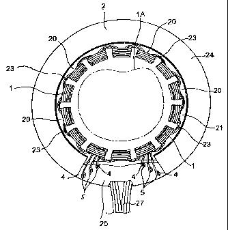
Fig. 1 is a plan view showing a terminal connection structure
of a resolver stator according to the present invention;
Fig. 2 is a sectional view of Fig. 1;
Fig. 3 is an enlarged sectional view of a main portion of Fig.
2;
Fig. 4 is an enlarged view of the stator coil of Fig. 1~
Fig. 5 is a perspective view showing a stator coil winding
and connecting portion in accordance with the present invention
and the prior arty
Fig. 6 is a perspective view showing a main portion of Fig.
1~
Fig. 7 is a perspective view showing a conventional winding
and connecting portions and
Fig. 8 is a perspective view showing how rupture occurs in
the winding and connecting portion of Fig. 7.
4


CA 02390208 2002-07-02
A preferred embodiment of a terminal connection structure of
a resolver stator coil in accordance with the present invention
will now be described with reference to the drawings. Components
the same as or equivalent to those of the conventional structure
will be indicated by the same reference numerals.
In Figs. 1 and 2, reference numeral 1 indicates a resolver
stator coil . This stator coil 1 is wound around magnetic pole teeth
20 of a stator 2 in which a rotor lA is arranged and which is formed
of an iron core, through an intermediation of a pair of annular
caps 21 and 22. The stator coil 1 is connected in series to the
magnetic pole teeth 20 through crossovers 23.
In a part of the outer peripheral edge 24 of the stator 2,
there is arranged a peripheral edge portion 25 which is formed so
as to radially protrude in a part of one of the insulating caps
21 and 22. Terminals 4 are planted to stand in this peripheral edge
portion 25.
The terminals 4 are formed integrally with a base portion 26,
and the terminals 4 and the base portion 26 form an L-shaped
configuration. Lead wires 27 are connected to the base portion 26,
and the terminals 4 are arranged so as to extend through holes (not
shown) of the peripheral edge portion 25 and protrude outwardly.
An insulation mold 10 is formed on the surface of the


CA 02390208 2002-07-02
peripheral edge portion 25, to which varnish coating, potting or
the like is applied. By means of this insulation mold 10, the
terminals 4 are secured in position as shown in Fig. 5, etc.
As shown in Figs. 4 and 5, the end portion 3 consists of a
portion near the end after winding the stator coil 1 around the
magnetic pole teeth 20. The end portion 3 wound around the outer
periphery of the terminal 4 a plurality of times forms the winding
connection portion 5 with the terminal 4.
The winding connection portion 5 as a whole, that is, the
terminal 4 as a whole is not integrated by soldering 6 or the like.
As in the prior art example shown in Fig. 7, as shown in Fig. 6,
the end portion 3 and the terminal 4 are formed into one by soldering
6 (or fusing) while leaving a plurality of turns of the lower portion
which is a part of the end portion 3 wound around the terminal 4.
The rest constitutes a free end portion 30 capable of independently
operating without being integrated with the terminal 4.
The free end portion 30 is wound around the outer periphery
of the terminal 4 a plurality of times, so that it functions like
a spring. If the stator coil 1 expands/contracts in the directions
of an arrow A due to thermal expansion, or when vibration in the
directions of the arrow A and vibration in the directions of the
arrows B perpendicular thereto occur due to vibration from outside,
most of the expansion/contraction and vibration can be absorbed
by the spring function and sagging function of the free end portion
6


CA 02390208 2002-07-02
30, whereby it is possible to prevent rupture or the like of the
end portion 3.
While in the above-described construction the free end
portion 30 is wound around the terminal 4 a plurality of times,
the above-mentioned spring function can be obtained by winding the
free end portion at least one time or even less than that, e.g.,
by 300 degrees, 250 degrees, etc.
The terminal connection structure of the resolver stator coil
in accordance with the present invention, constructed as described
above, provides the following advantage.
Instead of integrally fixing the entire end portion wound
around the stator coil terminal, a part of it is left as a free
end portion that is not wound around the terminal so that a spring
function and sagging function may be obtained, the remaining portion
being integrally fixed. Thus, if vibration is applied from outside
or expansion/contraction or the like occurs due to thermal expansion,
the vibration, etc. can be absorbed by the spring function and
sagging function, whereby it is possible to prevent breakage such
as rupture as in the prior art, thereby improving the resolver in
terms of reliability.
7

Representative Drawing
A single figure which represents the drawing illustrating the invention.
Administrative Status

For a clearer understanding of the status of the application/patent presented on this page, the site Disclaimer , as well as the definitions for Patent , Administrative Status , Maintenance Fee  and Payment History  should be consulted.

Administrative Status

Title Date
Forecasted Issue Date 2006-04-04
(22) Filed 2002-07-02
Examination Requested 2002-07-02
(41) Open to Public Inspection 2003-01-05
(45) Issued 2006-04-04
Deemed Expired 2010-07-02

Abandonment History

There is no abandonment history.

Payment History

Fee Type Anniversary Year Due Date Amount Paid Paid Date
Request for Examination $400.00 2002-07-02
Registration of a document - section 124 $100.00 2002-07-02
Application Fee $300.00 2002-07-02
Maintenance Fee - Application - New Act 2 2004-07-02 $100.00 2004-05-07
Maintenance Fee - Application - New Act 3 2005-07-04 $100.00 2005-05-31
Final Fee $300.00 2006-01-17
Maintenance Fee - Patent - New Act 4 2006-07-03 $100.00 2006-06-02
Maintenance Fee - Patent - New Act 5 2007-07-02 $200.00 2007-06-07
Maintenance Fee - Patent - New Act 6 2008-07-02 $200.00 2008-05-29
Owners on Record

Note: Records showing the ownership history in alphabetical order.

Current Owners on Record
TAMAGAWA SEIKI KABUSHIKI KAISHA
Past Owners on Record
MIMURA, HISASHI
Past Owners that do not appear in the "Owners on Record" listing will appear in other documentation within the application.
Documents

To view selected files, please enter reCAPTCHA code :


To view images, click a link in the Document Description column. To download the documents, select one or more checkboxes in the first column and then click the "Download Selected in PDF format (Zip Archive)" or the "Download Selected as Single PDF" button.

List of published and non-published patent-specific documents on the CPD .

If you have any difficulty accessing content, you can call the Client Service Centre at 1-866-997-1936 or send them an e-mail at CIPO Client Service Centre.


Document
Description 
Date
(yyyy-mm-dd) 
Number of pages   Size of Image (KB) 
Abstract 2002-07-02 1 20
Description 2002-07-02 7 261
Drawings 2002-07-02 8 95
Claims 2002-07-02 1 39
Representative Drawing 2002-10-04 1 12
Cover Page 2002-12-16 1 41
Claims 2004-09-16 2 69
Claims 2005-04-15 2 77
Representative Drawing 2006-03-09 1 17
Cover Page 2006-03-09 2 49
Assignment 2002-07-02 4 125
Prosecution-Amendment 2004-03-17 2 55
Correspondence 2005-03-01 1 13
Prosecution-Amendment 2004-09-16 5 149
Prosecution-Amendment 2005-04-04 2 40
Prosecution-Amendment 2005-04-15 2 90
Prosecution-Amendment 2006-01-17 1 40
Correspondence 2006-01-17 1 40