Some of the information on this Web page has been provided by external sources. The Government of Canada is not responsible for the accuracy, reliability or currency of the information supplied by external sources. Users wishing to rely upon this information should consult directly with the source of the information. Content provided by external sources is not subject to official languages, privacy and accessibility requirements.
Any discrepancies in the text and image of the Claims and Abstract are due to differing posting times. Text of the Claims and Abstract are posted:
| (12) Patent: | (11) CA 2390287 |
|---|---|
| (54) English Title: | ACOUSTIC SOURCE RANGE DETECTION SYSTEM |
| (54) French Title: | PROCEDE PERMETTANT DE DETERMINER SI UNE SOURCE ACOUSTIQUE SE TROUVE PRES OU LOIN D'UNE PAIRE DE MICROPHONES |
| Status: | Term Expired - Post Grant Beyond Limit |
| (51) International Patent Classification (IPC): |
|
|---|---|
| (72) Inventors : |
|
| (73) Owners : |
|
| (71) Applicants : |
|
| (74) Agent: | SMART & BIGGAR LP |
| (74) Associate agent: | |
| (45) Issued: | 2008-03-25 |
| (86) PCT Filing Date: | 2000-10-30 |
| (87) Open to Public Inspection: | 2001-05-17 |
| Examination requested: | 2005-07-29 |
| Availability of licence: | N/A |
| Dedicated to the Public: | N/A |
| (25) Language of filing: | English |
| Patent Cooperation Treaty (PCT): | Yes |
|---|---|
| (86) PCT Filing Number: | PCT/US2000/029862 |
| (87) International Publication Number: | WO 2001035118 |
| (85) National Entry: | 2002-05-03 |
| (30) Application Priority Data: | ||||||
|---|---|---|---|---|---|---|
|
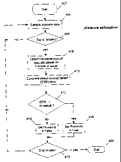
The invention includes a method, apparatus,
and computer program to determine whether a sound source is
situated near or far from a pair of microphones situated within
a reverberant space. A signal detector is applied to the data;
only the data that passes the signal detector is processed any
further. The signal at the two microphones is compared to
obtain the angular distribution of acoustic power. The concentration
of acoustic power in the direct path versus reverberant
paths is determined and used to compute a direct-to-reverberant
ratio. If this ratio is greater than a selected threshold, the
sound source is determined to be near the microphones. Otherwise,
the sound source is determined to be far from the microphones.
L'invention concerne un procédé, un appareil et un programme informatique permettant de déterminer si une source sonore se situe près ou loin d'une paire de microphones situés dans un espace réverbérant. Un détecteur de signaux est appliqué aux données; seules les données qui passent le détecteur de signaux continuent d'être traitées. Le signal au niveau des deux microphones est comparé afin d'obtenir la distribution angulaire de la puissance acoustique. La concentration de la puissance acoustique dans la voie directe par opposition à la voie réverbérante est déterminée et utilisée afin de calculer un ratio voie directe-voie réverbérante. Si ce ratio est supérieur à un seuil choisi, cela signifie que la source sonore se trouve près des microphones. Dans le cas contraire, la source se trouve loin des microphones.
Note: Claims are shown in the official language in which they were submitted.
Note: Descriptions are shown in the official language in which they were submitted.
2024-08-01:As part of the Next Generation Patents (NGP) transition, the Canadian Patents Database (CPD) now contains a more detailed Event History, which replicates the Event Log of our new back-office solution.
Please note that "Inactive:" events refers to events no longer in use in our new back-office solution.
For a clearer understanding of the status of the application/patent presented on this page, the site Disclaimer , as well as the definitions for Patent , Event History , Maintenance Fee and Payment History should be consulted.
| Description | Date |
|---|---|
| Inactive: Expired (new Act pat) | 2020-10-30 |
| Inactive: Recording certificate (Transfer) | 2020-07-27 |
| Inactive: Recording certificate (Transfer) | 2020-07-27 |
| Inactive: Recording certificate (Transfer) | 2020-07-27 |
| Common Representative Appointed | 2020-07-27 |
| Inactive: Correspondence - Transfer | 2020-06-19 |
| Inactive: Multiple transfers | 2020-05-20 |
| Change of Address or Method of Correspondence Request Received | 2019-11-20 |
| Common Representative Appointed | 2019-10-30 |
| Common Representative Appointed | 2019-10-30 |
| Letter Sent | 2014-09-04 |
| Inactive: Correspondence - Transfer | 2014-07-28 |
| Letter Sent | 2014-06-11 |
| Letter Sent | 2014-06-10 |
| Inactive: IPC expired | 2013-01-01 |
| Inactive: IPC expired | 2013-01-01 |
| Inactive: Correspondence - Transfer | 2012-02-29 |
| Inactive: Correspondence - Transfer | 2011-10-24 |
| Letter Sent | 2011-10-13 |
| Inactive: Late MF processed | 2010-10-07 |
| Revocation of Agent Requirements Determined Compliant | 2010-08-30 |
| Inactive: Office letter | 2010-08-30 |
| Inactive: Office letter | 2010-08-30 |
| Appointment of Agent Requirements Determined Compliant | 2010-08-30 |
| Appointment of Agent Request | 2010-08-04 |
| Revocation of Agent Request | 2010-08-04 |
| Letter Sent | 2010-07-23 |
| Letter Sent | 2009-10-30 |
| Inactive: Correspondence - Transfer | 2009-07-22 |
| Letter Sent | 2009-07-06 |
| Letter Sent | 2009-07-06 |
| Grant by Issuance | 2008-03-25 |
| Inactive: Cover page published | 2008-03-24 |
| Pre-grant | 2008-01-03 |
| Inactive: Final fee received | 2008-01-03 |
| Inactive: IPC assigned | 2007-12-10 |
| Letter Sent | 2007-12-10 |
| Notice of Allowance is Issued | 2007-12-10 |
| Notice of Allowance is Issued | 2007-12-10 |
| Inactive: IPC assigned | 2007-12-10 |
| Inactive: IPC removed | 2007-12-10 |
| Inactive: Approved for allowance (AFA) | 2007-09-11 |
| Letter Sent | 2007-01-19 |
| Amendment Received - Voluntary Amendment | 2007-01-17 |
| Inactive: Single transfer | 2006-12-08 |
| Inactive: S.30(2) Rules - Examiner requisition | 2006-08-09 |
| Inactive: S.29 Rules - Examiner requisition | 2006-08-09 |
| Amendment Received - Voluntary Amendment | 2005-10-28 |
| Letter Sent | 2005-09-01 |
| Request for Examination Received | 2005-07-29 |
| Request for Examination Requirements Determined Compliant | 2005-07-29 |
| All Requirements for Examination Determined Compliant | 2005-07-29 |
| Letter Sent | 2004-12-07 |
| Reinstatement Requirements Deemed Compliant for All Abandonment Reasons | 2004-11-22 |
| Deemed Abandoned - Failure to Respond to Maintenance Fee Notice | 2004-11-01 |
| Amendment Received - Voluntary Amendment | 2004-03-12 |
| Letter Sent | 2003-11-19 |
| Revocation of Agent Requirements Determined Compliant | 2003-11-10 |
| Inactive: Office letter | 2003-11-10 |
| Inactive: Office letter | 2003-11-10 |
| Letter Sent | 2003-11-10 |
| Letter Sent | 2003-11-10 |
| Appointment of Agent Requirements Determined Compliant | 2003-11-10 |
| Inactive: Adhoc Request Documented | 2003-10-30 |
| Revocation of Agent Request | 2003-10-21 |
| Appointment of Agent Request | 2003-10-21 |
| Inactive: Single transfer | 2003-10-10 |
| Inactive: Single transfer | 2003-10-10 |
| Inactive: Office letter | 2003-07-14 |
| Inactive: Correspondence - Transfer | 2003-05-01 |
| Letter Sent | 2003-04-22 |
| Letter Sent | 2003-04-22 |
| Letter Sent | 2003-04-22 |
| Letter Sent | 2003-04-22 |
| Inactive: Single transfer | 2003-02-20 |
| Inactive: Cover page published | 2002-12-24 |
| Inactive: Courtesy letter - Evidence | 2002-12-23 |
| Inactive: Notice - National entry - No RFE | 2002-12-19 |
| Inactive: Office letter | 2002-10-22 |
| Application Received - PCT | 2002-07-29 |
| National Entry Requirements Determined Compliant | 2002-05-03 |
| National Entry Requirements Determined Compliant | 2002-05-03 |
| Application Published (Open to Public Inspection) | 2001-05-17 |
| Abandonment Date | Reason | Reinstatement Date |
|---|---|---|
| 2004-11-01 |
The last payment was received on 2007-10-03
Note : If the full payment has not been received on or before the date indicated, a further fee may be required which may be one of the following
Please refer to the CIPO Patent Fees web page to see all current fee amounts.
Note: Records showing the ownership history in alphabetical order.
| Current Owners on Record |
|---|
| BLACKBERRY LIMITED |
| Past Owners on Record |
|---|
| PIERRE ZAKARAUSKAS |

