Language selection

Search

Patent 2390451 Summary

Third-party information liability

Some of the information on this Web page has been provided by external sources. The Government of Canada is not responsible for the accuracy, reliability or currency of the information supplied by external sources. Users wishing to rely upon this information should consult directly with the source of the information. Content provided by external sources is not subject to official languages, privacy and accessibility requirements.

Claims and Abstract availability

Any discrepancies in the text and image of the Claims and Abstract are due to differing posting times. Text of the Claims and Abstract are posted:

  • At the time the application is open to public inspection;
  • At the time of issue of the patent (grant).
(12) Patent: (11) CA 2390451
(54) English Title: CONDUCTIVE ELECTRICAL ELEMENT AND ANTENNA WITH INK ADDITIVE TECHNOLOGY
(54) French Title: ELEMENT CONDUCTEUR D'ELECTRICITE ET ANTENNE REALISES AVEC UNE ENCRE CONDUCTRICE
Status: Deemed expired
Bibliographic Data
(51) International Patent Classification (IPC):
  • G03F 7/16 (2006.01)
  • G01V 15/00 (2006.01)
  • G06K 19/077 (2006.01)
  • H01Q 1/38 (2006.01)
  • H05K 3/12 (2006.01)
  • H05K 1/16 (2006.01)
(72) Inventors :
  • HUFFER, SCOTT W. (United States of America)
  • SCHUETZ, JEFFREY M. (United States of America)
  • LOWRY, JAMES (United States of America)
(73) Owners :
  • SONOCO DEVELOPMENT, INC. (United States of America)
(71) Applicants :
  • SONOCO DEVELOPMENT, INC. (United States of America)
(74) Agent: MCCARTHY TETRAULT LLP
(74) Associate agent:
(45) Issued: 2010-08-17
(22) Filed Date: 2002-06-12
(41) Open to Public Inspection: 2003-04-09
Examination requested: 2007-04-26
Availability of licence: N/A
(25) Language of filing: English

Patent Cooperation Treaty (PCT): No

(30) Application Priority Data:
Application No. Country/Territory Date
09/973,494 United States of America 2001-10-09

Abstracts

English Abstract


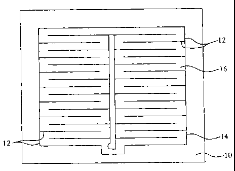
A printing process is provided in which a conductive ink is
printed over a printed pattern formed by a coating having an additive that
lowers
surface tension. Printed electrical elements and antennae (including RFID
antennae) are formed using this process. The coating with the surface tension
lowering additive is printed on a substrate in a predetermined pattern. A
conductive ink is then applied over the coating and, because of the difference
in
surface tension between the coating and the substrate, the ink flows away from
the coating. The conductive ink dries between the printed coating pattern and
forms the conductive element.


French Abstract

Un procédé d'impression dans lequel une encre conductrice est posée sur un motif imprimé formé à l'aide d'un enduit comportant un additif réducteur de tension superficielle. Ce procédé est utilisé pour la réalisation d'éléments électriques imprimés et d'antennes (y compris les antennes d'identification par radiofréquences ou RFID). L'enduit contenant l'additif réducteur de tension superficielle est posé sur un substrat selon un motif prédéterminé. Une encre conductrice est ensuite appliquée sur l'enduit et l'encre s'écoule en se séparant de l'enduit en raison de la différence de tension superficielle de l'enduit et du substrat. L'encre conductrice sèche entre le motif de l'enduit imprimé et forme l'élément conducteur.

Claims

Note: Claims are shown in the official language in which they were submitted.


Claims

What is claimed is:

1. A process for making a conductive element comprising
the steps of:
providing a conductive ink;
providing a coating;
adding a surface tension lowering additive to the coating;
pattern printing the coating onto a target zone on a substrate, the
target zone having coating printed areas and non-printed areas, the non-
printed
areas forming a shape for the conductive element;
applying the ink over the target zone; and
allowing the ink to flow from the coating printed areas to the
non-printed areas until the ink forms in the shape of the antenna.

2. The process of claim 1 wherein the coating printed areas
are printed such that non-printed areas are positioned between substantially
parallel lines of printed coating.

3. The process of claim 1 wherein the coating is a hydroxy-
functional resin.

4. The process of claim 3 wherein the resin coating is clear.

5. The process of claim 1 wherein the coating is a varnish.

6. The process of claim 1 wherein the coating is a pattern of
colored inks.

7. The process of claim 1 wherein the additive is hydroxy-
modified polyether silane.

8. The process of claim 1 wherein the substrate is a silicone
chip.

9. The process of claim 1 wherein the printing of the
conductive ink and the coating is performed using a laser engraved rotogravure
printing machine.

-6-


10. The process of claim 1, further comprising a protective
coating encapsulating the target zone.

11. The process of claim 1, further comprising the step of:
providing a radio frequency identification chip, the radio
frequency identification chip and the conductive element being in contact with
each other through a conductive material.

12. The process of claim 11, further comprising a protective
coating encapsulating the target zone.

13. The process of claim 11 wherein the additive is hydroxy-
modified polyether silane.

14. The process of claim 11 wherein the printing of the
conductive ink and the coating is performed using a laser engraved rotogravure
printing machine.

15. The process of claim 11 wherein the conductive material
is a conductive epoxy.

16. The process of claim 1 wherein the conductive element is
an antenna.

17. A conductive element comprising:
a coating having a surface tension lowering additive;
a conductive ink; and
a substrate having a target zone, the target zone having the
coating and conductive ink printed thereon; the target zone having coating
printed areas and ink printed areas, the coating printed areas forming a shape
for
the conductive element, the ink printed areas forming a pattern between the
coating printed areas.

18. The conductive element of claim 17 wherein the pattern is
an antenna.

19. The conductive element of claim 17 wherein the pattern is
a radio frequency identification antenna.

-7-


20. The conductive element of claim 17, further comprising a
protective coating encapsulating the target zone.

21. The conductive element of claim 17 wherein the additive
is hydroxy-modified polyether silane.

22. The conductive element of claim 17 wherein the printing
of the conductive ink and the coating is performed using laser engraved
rotogravure.

-8-

Description

Note: Descriptions are shown in the official language in which they were submitted.


CA 02390451 2002-06-12
CONDUCTIVE ELECTRICAL ELEMENT AND ANTENNA
WITH INK ADDITIVE TECHNOLOGY
Field of the Invention
[0001 ] The present invention relates to a method forming an electrical
element or antenna. More specifically, the present invention relates to a
method
for making an electrical element or antenna by printing a conductive ink over
a
pattern-printed coating.
1 S Background of the Aoulication
[0002] Conductive inks are used for printing electrical elements,
including antennae. In particular, conductive inks have been used to print
antennae for radio frequency identification (RFID) tags. RhID tags are used to
track inventory, confirm the validity of goods, and for other product tracking
and identification purposes.
[0003) Printed ink electrical components can be less expensive to
produce than their formed, stamped, or laser ablated counterparts. In
addition,
printed ink electrical components can be presented in an aesthetically
pleasing
manner. This is particularly important when considering the use of printed ink
2S antennae for use in tracking retail goods, since the common retail tracking
system uses a large unsightly tag, as opposed to the more decorative tag
afforded by using a printed ink antenna.
[0004) One current problem with printed ink electrical elements is that
the current printing technologies (using a screen-printing process) result in
ink
bleeding, which causes the conductive path in the element to short circuit.
This
problem is exaggerated for RFID antennae because a long uninterrupted
conductive path in an RFID antenna provides a more powerful antenna; ink
bleeding becomes more probable with this longer path. Thus there is a need for
36765-149932 302760ISBS
-1-

CA 02390451 2002-06-12
making long uninterrupted paths of printed conductive ink. The present
invention provides a process for printing such paths of conductive ink, and
also
discloses using this process in antennae and RFID applications.
Summary of the Invention
[0005] The present invention provides a printing process in which a
conductive ink is printed over a coating having an additive that lowers
surface
tension. The coating with the surface tension lowering additive is pattern
printed
on a substrate in a predetermined pattern, and a conductive ink is then
applied
over the coating. Due to the difference in surface tension between the coating
and the substrate, the ink flows away from the coating, forming the shape for
a
conductive element.
[0006] The conductive element may be an antennae or an RFID
antennae.
Brief Description of the Drawings
[0007) For the purpose of illustrating the invention, there is shown in the
drawings a form which is presently preferred; it being understood, however,
that
this invention is not limited to the precise arrangements and
instrumentalities
shown.
[0008] Figure 1 is a top view of the coating pattern printed on a
substrate.
[0009] Figure 2 is a top view of the conductive ink printed over the
coating pattern of Figure 1.
[0010] Figure 3 is a cross section showing conductive ink applied over a
pattern printed coating according to the present invention.
[0011 ] Figure 4 is a cross section showing conductive ink which has
flowed into the spaces between the pattern.
[0012] Figure 5 is a cross section showing a protective coating applied
over the pattern printed coating and conductive ink.
[0013] Figure 6 is a partial enlarged section of a printed electrical
component or antenna according to the present invention.
36765-149932 3027601SHS
-2-

CA 02390451 2002-06-12
Detailed Il~scriotion~f the D~,awines
[0(?14] In the drawings, where like numerals identify similar elements,
there are shown different views of printed matter according to the present
invention. Figure 1 shows the additive enhanced coating 12 printed over the
substrate 10 in a pattern suitable for an antenna, leaving spaces between
adjacent lines of coating so that the substrate 10 remains exposed in the non-
printed areas 16. The coating printed areas 12 are contained within the target
zone 14 on the substrate 10. It should be understood that the target zone 14
could be the same size as the substrate 10 for some applications. The
substrate is
preferably a silicone chip.
[0015] Before printing, the coating is combined with an additive which
lowers the surface tension of the dried coating. One such additive is a
hydroxy-
modified polyether silane manufactured and sold by BYK-Chemie. The coating
is preferably a hydroxy-functional resin such as Acrylic 928-1663, although
other resins or varnishes may perform equally as effectively or better than
Acrylic 92$-1663.
[0016] Figure 2 shows the pattern printed coating 12 shown in Figure 1
after the conductive ink 18 has been printed over the target zone 14. Because
of
the surface lowering additive in the coating 12, the conductive ink 18 flows
away from the coating 12. Figure 6 shows an unscaled enlarged partial section
showing the coating with the ink printed thereon.
[0017] The particular printing method used to apply the conductive ink
to the substrate is not important, and those of ordinary skill in the art will
recognize that a variety of printing methods are available. One example of a
suitable printing method is the rotogravure process. Rotogravure is preferable
because it produces highly accurate images, while allowing for high press and
production speeds. Rotogravure cylinders engraved by a laser engraver will
yield both the production volume and continuous channels necessary to produce
the desired continuous and high volume flow of conductive ink necessary to
achieve an improved printed electrical element or antenna.
36765-149932 3029601SBS
-3-

CA 02390451 2002-06-12
[0018] The laser engraver is capable of engraving deep continuous
channels for the ink. Mechanical engraving with a diamond stylus will produce
large cells with narrow channels of a much smaller volume.
[0019] It should be understood that with the use of a laser engraver,
highly accurate patterns can be created. Also, more volume of the ink can be
deposited on the surface due to the large volume of cells produced on the
laser
engraver. This large volume is possible with the present invention
substantially
without the occurrence of "flow outs" or bleeding. This bleeding of the
conductive ink results in short outs in the antenna and may be more common in
non-laser engraved printing processes.
[0020] Figures 3 and 4 show the ink printing and flow in cross section.
Figure 3 is a cross section of the target zone immediately after the ink 18
has
been applied. The ink 18 is in contact with both the printed, dried coating 12
and
the substrate 10 between lines of coating 12. Because the surface tension of
the
dried coating 12 is lower than the surface tension of the substrate 10, the
ink 18
flows away from the dried coating 12 and toward the areas of exposed substrate
10.
[0021] Figure 4 shows a cross section of printed matter according to the
invention after the ink 18 has completed its flow. The ink 18 has collected in
the
areas of exposed substrate 10 between the profile lines of coating 12. As
shown,
the ink 18 forms raised ridges that are oriented along the patterned lines of
coating 12, though it would be recognized by one skilled in the art that with
less
ink, these ridges would be reduced or eliminated. The ink 18 dries between the
lines of the coating pattern 12. Without the additive in the coating, the ink
would normally flow out and dry in a continuous film (as shown in Figure 3)
and would not yield the continuous uninterrupted electrical element desired.
[0022] Figure 5 shows a further embodiment of the invention of the
application wherein a protective coating 20 is applied over the target zone 14
(although the protective coating could be applied over the entire substrate
10, if
36765-149932 302760fS8S
.. G~ _

CA 02390451 2002-06-12
desired). This protective coating prevents damage to the electrical element or
antenna contained within the target zone.
[0023] When using the above described process to form an RFID
element, the RFID antenna would be connected to an RFID chip through a
conductive material, such as a conductive epoxy. The manner of forming an
RFID element using an RFID chip and antenna is described in U.S. Pat. No.
6,147,662 to Grabau et al., and is incorporated herein by reference.
[0024] The present invention may be embodied in still further specific
forms using different inks, surface tension lowering additives, coatings,
patterns
for antennae, protective coatings, and substrates, without departing from the
spirit or essential attributes thereof and, accordingly, reference should be
made
to the appended claims, rather than to the foregoing specification, as
indicating
the scope of the invention.
36765-149932
_5_

Representative Drawing
A single figure which represents the drawing illustrating the invention.
Administrative Status

For a clearer understanding of the status of the application/patent presented on this page, the site Disclaimer , as well as the definitions for Patent , Administrative Status , Maintenance Fee  and Payment History  should be consulted.

Administrative Status

Title Date
Forecasted Issue Date 2010-08-17
(22) Filed 2002-06-12
(41) Open to Public Inspection 2003-04-09
Examination Requested 2007-04-26
(45) Issued 2010-08-17
Deemed Expired 2013-06-12

Abandonment History

There is no abandonment history.

Payment History

Fee Type Anniversary Year Due Date Amount Paid Paid Date
Registration of a document - section 124 $100.00 2002-06-12
Application Fee $300.00 2002-06-12
Maintenance Fee - Application - New Act 2 2004-06-14 $100.00 2004-03-29
Maintenance Fee - Application - New Act 3 2005-06-13 $100.00 2005-03-30
Maintenance Fee - Application - New Act 4 2006-06-12 $100.00 2006-06-07
Request for Examination $800.00 2007-04-26
Maintenance Fee - Application - New Act 5 2007-06-12 $200.00 2007-06-05
Maintenance Fee - Application - New Act 6 2008-06-12 $200.00 2008-05-06
Maintenance Fee - Application - New Act 7 2009-06-12 $200.00 2009-06-03
Final Fee $300.00 2010-04-16
Maintenance Fee - Application - New Act 8 2010-06-14 $200.00 2010-06-02
Maintenance Fee - Patent - New Act 9 2011-06-13 $200.00 2011-05-11
Owners on Record

Note: Records showing the ownership history in alphabetical order.

Current Owners on Record
SONOCO DEVELOPMENT, INC.
Past Owners on Record
HUFFER, SCOTT W.
LOWRY, JAMES
SCHUETZ, JEFFREY M.
Past Owners that do not appear in the "Owners on Record" listing will appear in other documentation within the application.
Documents

To view selected files, please enter reCAPTCHA code :


To view images, click a link in the Document Description column. To download the documents, select one or more checkboxes in the first column and then click the "Download Selected in PDF format (Zip Archive)" or the "Download Selected as Single PDF" button.

List of published and non-published patent-specific documents on the CPD .

If you have any difficulty accessing content, you can call the Client Service Centre at 1-866-997-1936 or send them an e-mail at CIPO Client Service Centre.


Document
Description 
Date
(yyyy-mm-dd) 
Number of pages   Size of Image (KB) 
Representative Drawing 2002-10-10 1 9
Cover Page 2003-03-14 1 39
Abstract 2002-06-12 1 18
Claims 2002-06-12 3 84
Description 2002-06-12 5 220
Drawings 2002-06-12 3 124
Representative Drawing 2010-07-22 1 11
Cover Page 2010-07-22 2 45
Claims 2010-01-06 3 74
Description 2010-01-06 5 214
Correspondence 2006-06-07 1 24
Fees 2006-06-07 1 25
Assignment 2002-06-12 8 328
Correspondence 2005-06-02 11 496
Prosecution-Amendment 2007-07-18 1 40
Fees 2008-05-06 1 29
Correspondence 2005-06-08 1 14
Correspondence 2005-06-09 1 16
Prosecution-Amendment 2007-04-26 1 32
Fees 2007-06-05 1 26
Fees 2009-06-03 1 35
Prosecution-Amendment 2009-12-07 2 42
Prosecution-Amendment 2010-01-06 8 227
Correspondence 2010-04-16 1 38
Fees 2010-06-02 1 37