Language selection

Search

Patent 2390732 Summary

Third-party information liability

Some of the information on this Web page has been provided by external sources. The Government of Canada is not responsible for the accuracy, reliability or currency of the information supplied by external sources. Users wishing to rely upon this information should consult directly with the source of the information. Content provided by external sources is not subject to official languages, privacy and accessibility requirements.

Claims and Abstract availability

Any discrepancies in the text and image of the Claims and Abstract are due to differing posting times. Text of the Claims and Abstract are posted:

  • At the time the application is open to public inspection;
  • At the time of issue of the patent (grant).
(12) Patent: (11) CA 2390732
(54) English Title: ROOF CURB INSTALLATION TOOL
(54) French Title: OUTIL D'INSTALLATION DE REBORD DE TOIT
Status: Expired and beyond the Period of Reversal
Bibliographic Data
(51) International Patent Classification (IPC):
  • E04G 23/03 (2006.01)
  • E04D 13/03 (2006.01)
  • E04D 15/00 (2006.01)
(72) Inventors :
  • GRABMEIER, RICHARD JAMES (United States of America)
(73) Owners :
  • BLUESCOPE BUILDINGS NORTH AMERICA, INC.
(71) Applicants :
  • BUTLER MANUFACTURING COMPANY, INC. (United States of America)
(74) Agent: MARKS & CLERK
(74) Associate agent:
(45) Issued: 2006-11-21
(22) Filed Date: 2002-06-13
(41) Open to Public Inspection: 2003-12-13
Examination requested: 2002-06-13
Availability of licence: N/A
Dedicated to the Public: N/A
(25) Language of filing: English

Patent Cooperation Treaty (PCT): No

(30) Application Priority Data: None

Abstracts

English Abstract

A roof curb installation tool has a pair of sliding hinged hooks for lifting the edge of a metal roof panel, and a pair of clamping tangs which can be secured to a vertical roof seam while a curb is being installed at a hole in the roof.


French Abstract

Outil d'installation de rebord de toit ayant une paire de crochets à charnière coulissants pour lever le bord d'un panneau de toit métallique, et une paire de languettes de fixation qui peuvent être fixées solidement à un joint de toit vertical pendant qu'un rebord est installé au niveau d'un trou dans le toit.

Claims

Note: Claims are shown in the official language in which they were submitted.

6
The embodiments of the invention in which an exclusive property or privilege
is claimed are defined as follows:
1. A roof curb installation tool for lifting and holding an edge of a metal
panel running transverse to a standing seam previously formed between that
panel and an adjacent panel, said tool comprising
an elongate bar,
at least two carriers, each having a body adapted for sliding along said
bar,
each body having a hinge and a hook connected to the body by said
hinge, and
a pair of clamping tangs welded to said bar adjacent one another, with
a space between them just sufficient to receive the standing seam.
2. The tool of claim 1, wherein the bar has a series of holes, and each
carrier has a spring-loaded pin adapted to engage in any of said holes,
whereby the location of the carrier on the bar may be changed.
3. The tool of claim 1, wherein the bar has a rectangular cross-section
and thus four longitudinal edges, and the clamping tangs extend upward from
one of said edges, and
each carrier body has a rectangular cross-section with the hinge
mounted at one of the longitudinal edges of the body, said body being
installed on said bar so that said hinge and said tangs are diagonally
opposite
to one another.

7
4. The tool of claim 1, wherein said clamping tangs are disposed on the
bar substantially midway between its ends, and at least one of said carriers
is
installed on either side of said tangs.
5. The tool of claim 1, wherein each of said hooks has a flattened tip so
that it can be inserted into a narrow gap beneath a roof panel.
6. A method of lifting and holding an edge of a metal roof panel running
transverse to a standing seam previously formed between that panel and an
adjacent panel, said method comprising steps of
providing a tool having an elongate bar, a pair of carriers each having a
body adapted for sliding along said bar and a hook hinged to the body, and a
pair of clamping tangs welded to said bar adjacent one another, with a space
between them just sufficient to receive the standing seam,
placing the tool transversely across the seam, and parallel to and
above said edge, with said clamping tangs disposed vertically above and
astride the seam,
engaging said hooks beneath said edge,
rotating the bar so as to draw the hooks upward and force the clamping
tangs downward against the roof panels, and
applying a clamp to the seam above the clamping tangs to secure the
bar in its rotated position.

Description

Note: Descriptions are shown in the official language in which they were submitted.


CA 02390732 2005-12-23
2
SUMMARY OF THE INVENTION
The invention is directed towards facilitating the placement of internally
flanged curbs on metal roofs.
The present invention is directed towards the provisions to workers of a tool
with which they can lift up and hold the edge of a metal panel while
installing a curb
on a seamed roof.
In accordance with one aspect of the present invention, there is provided a
roof
curb installation tool for lifting and holding an edge of a metal panel
running
transverse to a standing seam previously formed between that panel and an
adjacent
panel, said tool comprising
an elongate bar,
at least two carriers, each having a body adapted for sliding along said bar,
each body having a hinge and a hook connected to the body by said hinge, and
a pair of clamping tangs welded to said bar adjacent one another, with a space
between them just sufficient to receive the standing seam.
In accordance with another aspect of the present invention, there is provided
a
method of lifting and holding an edge of a metal roof panel running transverse
to a
standing seam previously formed between that panel and an adjacent panel, said
method comprising steps of
providing a tool having an elongate bar, a pair of carriers each having a body
adapted for sliding along said bar and a hook hinged to the body, and a pair
of
clamping tangs welded to said bar adjacent one another, with a space between
them
just sufficient to receive the standing seam,
placing the tool transversely across the seam, and parallel to and above said
edge, with said clamping tangs disposed vertically above and astride the seam,

CA 02390732 2005-12-23
engaging said hooks beneath said edge,
rotating the bar so as to draw the hooks upward and force the clamping tangs
downward against the roof panels, and
applying a clamp to the seam above the clamping tangs to secure the bar in its
rotated position.
BRIEF DESCRIPTION OF THE DRAWINGS
In the accompanying drawings,
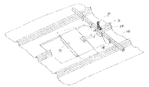
Figure 1 is an isometric view of a roof curb installation tool embodying the
invention;
Figure 2 is a detail of a hook carrier shown in Figure 1;
Figure 3 is a perspective view of the tool as it is first applied a curb
installation
j ob; and
Figure 4 - 6 show, in a simplified form, a sequence of steps in which the curb
installation is effected.

CA 02390732 2005-12-23
4
DESCRIPTION OF THE PREFERRED EMBODIMENT
A roof curb installation tool embodying the invention includes a bar 10 of
metal tube
stock having two or more adjustable sliding carrier assemblies 12 thereon. The
bar has a
rectangular (preferably square) cross section, and thus has four longitudinal
edges. A four-
foot length of two-inch square stock is presently contemplated, but the best
dimensions may
vary with the application. Longer lengths could be built up from two or more
bars having a
telescoping fit or complementary ends shaped as pins and sockets.
Two roof seam clamping 14 tangs are welded to one face of the bar, midway
between
its ends, and extend perpendicularly away from the face at one of the edges.
Each adjustable carrier assembly includes a body 16 having a sliding fit on
the bar 10,
and a hook 18 attached thereto by means of a hinge 20. The carrier is oriented
with respect to
the bar so that the hinges and the clamping tangs are diagonally opposite one
another, when
viewed along the length of the bar.
The ends 22 of the hooks are flat, so that they can be inserted into a narrow
gap
beneath a roof panel, and are bent at about a ninety degree angle
approximately 2 3/4" from the
hinge points, allowing the hook ends to extend just below the flats of fully
seamed MR-24
panels when the tool body is laid across the seams and rotated so that the
hinge points are at
the lowest point on the tube.
The fact that the bodies can slide on the bar allows the hooks to be placed at
various
intervals along the length of the bar. A series of holes 26 are drilled
through at least one wall
of the bar, and the carrier assembly 12 has a latch mechanism which releasably
engages any
of the holes. The latch mechanism includes a U-shaped bracket 28 whose arms
are welded to
the body, an a T-shaped pin 30 which extends through a hole 32 in the bracket
and an aligned
hole 34 in the body. A compression spring 36 is disposed on the pin, between
the bottom
surface of the bracket, and a shoulder 38 on the pin. The spring urges the pin
toward the bar,
so it snaps into a hole 26 in the bar when that hole is aligned with holes 32
and 34. One
releases the pin from the bar by pulling up on the handle 40.
The seam clamping tangs referred to above are short U-channel-shaped metal
pieces
attached near the center of the tube and spaced just far enough apart to
straddle the machine-
formed portion of the MR-24 and VRS panel seams.

CA 02390732 2005-12-23
The tool is particularly useful for lifting the flat portion of the up-slope
roof panels
above the plane of the roof, so that a worker to can slide an internally
flanged curb diverter
plate "D" beneath a roof panel, as suggested in Figure 3: The process,
illustrated in Figs.
4 - 7, is described below.
After a hole has been cut in the roof, the curb installation tool is placed
across the roof
panel seams just over the upslope edge of the hole. The tool is oriented with
the hooks 18
facing the down slope direction and the clamping tangs 14 facing
perpendicularly up from the
roof plane. The bar is placed with the clamping tangs above a roof panel seam,
one on either
side of the seam.
The hooks 18 are allowed to hang downward from the tool body, with their ends
extending underneath the edges of the roof panels. The, carrier assemblies 12
are then moved
along the tool body, if necessary, to desired lifting spots on the panel
edges.
With the hooks now engaged under the roof panels (Fig. 4), the bar is rolled
(Fig. 5)
in an upslope direction one-quarter turn. This rotation draws the hooks
upward, and the
hooks lift the flat portions of the panels as a consequence. The clamping
tangs pass
downward, as the bar is turned, on either side of the roof seam "S" over which
they have been
centered, and come to rest (Fig. 6) against the tops of the metal panels. Now
a locking pliers
"P" (Figs. 3 and 6) is attached tightly to the roof panel seam, holding the
clamping tangs
down against the panels, thus keeping the tool body from rotating back to its
initial position.
The tool is left in the rotated position until the diverter plate has been
properly positioned
under the roof panels.
After the diverter plate has been inserted under the roof panel edge, the
locking pliers
may be removed from the panel seam and the curb installation tool is allowed
to rotate back
to its original position. The hooks are then slid out from between the roof
panels and the
diverter plate, and the curb installation tool is removed.
Since the invention is subject to modifications and variations, it is intended
that the
foregoing description and the accompanying drawings shall be interpreted as
only illustrative
of the invention defined by the following claims.

Representative Drawing
A single figure which represents the drawing illustrating the invention.
Administrative Status

2024-08-01:As part of the Next Generation Patents (NGP) transition, the Canadian Patents Database (CPD) now contains a more detailed Event History, which replicates the Event Log of our new back-office solution.

Please note that "Inactive:" events refers to events no longer in use in our new back-office solution.

For a clearer understanding of the status of the application/patent presented on this page, the site Disclaimer , as well as the definitions for Patent , Event History , Maintenance Fee  and Payment History  should be consulted.

Event History

Description Date
Time Limit for Reversal Expired 2018-06-13
Letter Sent 2017-06-13
Letter Sent 2009-05-13
Grant by Issuance 2006-11-21
Inactive: Cover page published 2006-11-20
Inactive: Final fee received 2006-09-08
Pre-grant 2006-09-08
Notice of Allowance is Issued 2006-07-26
Letter Sent 2006-07-26
Notice of Allowance is Issued 2006-07-26
Inactive: IPC from MCD 2006-03-12
Inactive: Received pages at allowance 2005-12-23
Inactive: Office letter 2005-10-24
Inactive: Office letter 2005-08-10
Inactive: Approved for allowance (AFA) 2005-07-27
Application Published (Open to Public Inspection) 2003-12-13
Inactive: Cover page published 2003-12-12
Amendment Received - Voluntary Amendment 2002-12-19
Inactive: First IPC assigned 2002-09-20
Inactive: IPC assigned 2002-09-20
Inactive: Filing certificate - RFE (English) 2002-08-01
Filing Requirements Determined Compliant 2002-08-01
Letter Sent 2002-08-01
Application Received - Regular National 2002-08-01
Request for Examination Requirements Determined Compliant 2002-06-13
All Requirements for Examination Determined Compliant 2002-06-13

Abandonment History

There is no abandonment history.

Maintenance Fee

The last payment was received on 2006-01-25

Note : If the full payment has not been received on or before the date indicated, a further fee may be required which may be one of the following

  • the reinstatement fee;
  • the late payment fee; or
  • additional fee to reverse deemed expiry.

Please refer to the CIPO Patent Fees web page to see all current fee amounts.

Owners on Record

Note: Records showing the ownership history in alphabetical order.

Current Owners on Record
BLUESCOPE BUILDINGS NORTH AMERICA, INC.
Past Owners on Record
RICHARD JAMES GRABMEIER
Past Owners that do not appear in the "Owners on Record" listing will appear in other documentation within the application.
Documents

To view selected files, please enter reCAPTCHA code :


To view images, click a link in the Document Description column. To download the documents, select one or more checkboxes in the first column and then click the "Download Selected in PDF format (Zip Archive)" or the "Download Selected as Single PDF" button.

List of published and non-published patent-specific documents on the CPD .

If you have any difficulty accessing content, you can call the Client Service Centre at 1-866-997-1936 or send them an e-mail at CIPO Client Service Centre.


Document
Description 
Date
(yyyy-mm-dd) 
Number of pages   Size of Image (KB) 
Representative drawing 2002-11-19 1 16
Description 2002-12-19 5 221
Cover Page 2003-11-17 1 36
Abstract 2002-06-13 1 8
Drawings 2002-06-13 4 76
Description 2002-06-13 4 172
Claims 2002-06-13 2 63
Description 2005-12-23 4 162
Claims 2005-12-23 2 60
Representative drawing 2006-10-26 1 16
Cover Page 2006-10-26 1 38
Acknowledgement of Request for Examination 2002-08-01 1 193
Courtesy - Certificate of registration (related document(s)) 2002-08-01 1 134
Filing Certificate (English) 2002-08-01 1 173
Commissioner's Notice - Application Found Allowable 2006-07-26 1 162
Maintenance Fee Notice 2017-07-25 1 178
Fees 2004-01-22 1 49
Fees 2005-01-21 1 51
Correspondence 2005-10-24 1 21
Correspondence 2005-12-23 8 251
Fees 2006-01-25 1 52
Correspondence 2006-09-08 1 50
Fees 2007-06-08 1 52
Fees 2008-06-13 1 59
Fees 2009-06-11 1 65