Language selection

Search

Patent 2391253 Summary

Third-party information liability

Some of the information on this Web page has been provided by external sources. The Government of Canada is not responsible for the accuracy, reliability or currency of the information supplied by external sources. Users wishing to rely upon this information should consult directly with the source of the information. Content provided by external sources is not subject to official languages, privacy and accessibility requirements.

Claims and Abstract availability

Any discrepancies in the text and image of the Claims and Abstract are due to differing posting times. Text of the Claims and Abstract are posted:

  • At the time the application is open to public inspection;
  • At the time of issue of the patent (grant).
(12) Patent Application: (11) CA 2391253
(54) English Title: COLLAPSIBLE UPRIGHT DISPLAY UNIT
(54) French Title: PRESENTOIR VERTICAL PLIANT
Status: Deemed Abandoned and Beyond the Period of Reinstatement - Pending Response to Notice of Disregarded Communication
Bibliographic Data
(51) International Patent Classification (IPC):
  • G09F 7/00 (2006.01)
  • G09F 15/00 (2006.01)
(72) Inventors :
  • CAYER, CHRISTOPHER GEORGE (Canada)
  • GOULET, MARCEL (Canada)
  • GOULET, MICHELE (Canada)
(73) Owners :
  • KALEIDOSPHERE MARKETING CONCEPTS INC.
(71) Applicants :
  • KALEIDOSPHERE MARKETING CONCEPTS INC. (Canada)
(74) Agent: GOWLING WLG (CANADA) LLP
(74) Associate agent:
(45) Issued:
(22) Filed Date: 2002-06-25
(41) Open to Public Inspection: 2003-12-25
Examination requested: 2002-06-25
Availability of licence: N/A
Dedicated to the Public: N/A
(25) Language of filing: English

Patent Cooperation Treaty (PCT): No

(30) Application Priority Data: None

Abstracts

English Abstract


A collapsible upright display unit is provided that can easily be disassembled
and
transported. It involves a display sheet and parabolic support members which
are joined by
disconnectable connecting means to both tension the display sheet and act as a
stand to hold
the display sheet upright.


Claims

Note: Claims are shown in the official language in which they were submitted.

THE EMBODIMENTS OF THE INVENTION IN WHICH AN EXCLUSIVE PROPERTY
OR PRIVILEGE IS CLAIMED ARE DEFINED AS FOLLOWS:
1. A collapsible upright display unit comprising a flexible display sheet,
sockets at each
corner of the display sheet, first and second resilient parabolic support
members, the first
parabolic support member having the free ends of each leg engaging the sockets
at the upper
corner of the display sheet, the lowest section of the first parabolic support
member being
spaced from the sheet and providing a support for maintaining the sheet
upright, a second
parabolic member having free ends of each leg engaging the sockets at the
lower corners of
the display sheet and having a central portion extending through the plane of
the first
parabolic member and bearing against the first parabolic member to maintain
the first
parabolic member spaced from the sheet, a disconnectable connecting means
between the first
and second parabolic support members to maintain them in a relationship which
supports the
display unit in an upright position and disconnectable connecting means
between the display
unit and the first parabolic member to limit outward movement of the first
parabolic member.
2. ~A collapsible upright display unit as in claim 1 in which connecting means
are
provided between the legs of the first parabolic member to limit outward
spread of the legs.
3. ~A collapsible upright display unit as in claim 2 in which the connecting
means is a
strap.
4. ~A collapsible upright display unit as in claim 3 in which there is a
washer connected
to each leg of the first parabolic member to limit movement of the straps.
5. ~A collapsible upright display unit as in claim 1 in which the
disconnectable
connecting means between the first and second parabolic support members is a
strap which is
centrally located in each parabolic support member.
6. ~A collapsible upright display unit as in claim 5 in which the second
parabolic support
member is inside of the first parabolic support member at points of
intersection.
-5-

7. ~A collapsible upright display, unit as in claim 1 in which the
disconnectable
connecting means between the display unit and the first parabolic member
comprises straps
connected between the lower corners of the display sheet and the first
parabolic member.
8. ~A collapsible upright display unit as in claim 1 in which there are
lateral and top and
bottom resilient frame poles adapted removably to fit within the corner
braces.
9. ~A collapsible upright display unit as in claim 1 in which the parabolic
members are
formed from sections of aluminum tubing separately connected by an elastic
cord within the
tubing.
10. ~A collapsible upright display unit as in claim 8 in which the parabolic
members and
the frame poles are formed from sections of aluminum tubing separately
connected by an
elastic cord within the tubing.
11. ~A collapsible upright display unit as in claim 8 where the sockets are
provided by
blocks apertured to receive the parabolic member and the frame poles.
12. ~A collapsible upright display unit as in claim 1 where the sockets are
provided by
triangular pieces of material secured along the edges to the display sheet.
-6-

Description

Note: Descriptions are shown in the official language in which they were submitted.


CA 02391253 2002-06-25
Background of the Invention
This invention relates to a collapsible display unit.
A need has been identified for a display unit that is easily collapsible and
transportable and is inexpensive. Display and event marketing and
presentations of all kinds
have become increasingly popular as a marketing tool. What has also increased
is the
expense. It is estimated that the average cost per day for a business to have
a booth at a trade
show or similar event is between $8,000 and $25,000 per 10' x 10' hooth area
per day.
Smaller companies cannot afford this expense.
A significant contribution to the cost of booths at trade shows is the display
unit,
which is usually necessary for a sales presentation. So called "pop up" units
are available,
such as the structure described in Canadian Patent Application 2,194;330 filed
January 3,
1997. However, this '.and similar equipment is expensive to purchase or rent.
As the units
must usually be shipped instead of being transported by car, there is not only
additional
expense but concerns as to whether it will arrive on time and intact.
Another need is for inexpensive and xeadily portable in-store displays. There
is also a
requirement for a readily portable projection screen for audiovisual
presentations and other
multi-media events.
An object of this invention is therefore: to provide a collapsible display
unit which can
readily be disassembled for convenient transportation. It is furthermore an
object to provide
such collapsible display unit that is both light in weight and inexpensive.
Summary of the Invention
In accordance with one aspect of the invention, there is provided a
collapsible uptight
display unit comprising a flexible display sheet, sockets at each corner of
the display sheet,
first and second resilient parabolic support members; the first parabolic
support member
having the free ends of each leg engaging the sockets at the upper corner of
the display sheet,
the lowest section of the first parabolic support member being spaced from the
sheet and
providing a support for maintaining the sheet upright, a second parabolic
member having free
ends of each leg engaging the sockets at the lower corners of the display
sheet and having a
central portion extending through the plane of the first parabolic member and
bearing against
the first parabolic member to maintain the first parabolic member spaced from
the sheet, a

CA 02391253 2002-06-25
disconnectable connecting means between the first and second parabolic support
members to
maintain them in a relationship which supports the display unit in an upright
position and
disconnectable connecting means between the display unit and the first
parabolic member to
limit outward movement of the first parabolic member:
Brief Description of the Drawings
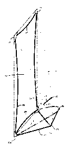
Figure 1 is an elevation view of one embodiment of the invention:
Figure 2 is a side elevation view ofthe embodiment shown in Figure 1.
Figure 3 is a top view of the embodiment shown in Figure 1.
Figure 4 is a detailed perspective view of part of the structure shown in
Figures l; 2
and 3.
Figure 5 is a sectional detailed view showing the parabolic and free members.
Figure 6 is a detailed perspective view of another embodiment of the
invention.
Figures 7, 8 and 9 are similar to Figures 1, 2 and 3 respectively but showing
an
alternative embodiment without the frame poles of Figures 1; 2 and 3.
Detailed Description
Referring now to Figures l to 9 of the drawings, there is shown a display
sheet 10 of
lightweight flexible material such as polyester microfiber. A wide range of
materials may be
used including nylon or other plastic material or a fabric such as canvas:
Where the invention
is to be used to provide a projection screen, a reflective surface can be
provided on a backing
such as nylon.
At each corner of display sheet 10; a socket 11 or l l a is provided by a
triangular piece
12 which may be of the same material as sheet 10 and which is sewn, as shown;
adhered, or
otherwise secured along its outer edges 13 to sheet l0.
A first resilient parabolic support member 14 has its free ends 15 engaging
sockets 11.
Parabolic support member 14 may be of lightweight resilient material such as
aluminum
tubing. In the case of small units; the material known under the trade name
Fiberglass may
be used. Because of its resilience, it tensions sheet 10 between upper sockets
11: The bottom
part 16 of parabolic support member 14 is spaced in a horizontal direction
from sheet l 1 to
provide a support for maintaining sheet l 0 upright.
-2-

CA 02391253 2002-06-25
A second parabolic support member 17 has its free ends engaging the sockets 11
a at
the lower corners of display sheet 10. Support member 17 may be of the same
material as
support member 14 and it has resilience to tension sheet 10 between lower
sockets 11 a.
Second parabolic support member 17 extends through the plane of first
parabolic support
member 14 as best shown in Figures 2 and 4. At the points of intersection 18
of the first and
second parabolic support members, the second support member 17 is within the
first support
member 14 so as to prevent support member 14 moving inwardly towards sheet 10
from the
position shown in Figure 2.
The combined effect of parabolic support members 14 and 17 is to maintain
sheet 10
in an upright position but preferably slightly inclined in the direction of
the, support members
for best stability, as apparent from ide elevation view Fig. 2 and plan view
Fig. 3. There is
also the combined effect of tensioning sheet 10 in each direction.
A strap 19 is secured between the bottom 16 of the first parabolic support
member and
the top 20 of the second parabolic support member. As illustrated in detailed
view 4, each
end of the strap is conveniently tied at 16 and 20 to a parabolic support
member.
The function of strap 19 is to prevent second parabolic support member 17 from
pivoting up and inwardly towards sheet 10. It is important to the
collapsability of the display
unit that at least one end of strap 19 be disconnectable. Other connecting
means could be
used such as clamps at the points of intersection 18 of the first and second
parabolic
members: If clamps were used, the second parabolic means 17 could be outside
instead of
inside parabolic member 14 as shown in-Figures 1 to 4.
A V-shaped strap 21 has its branches secured by being stitched to sheet 10 as
shown
in Figure 4, adjacent each ofthe lower corner sockets l la. The central
portion 23 of V-
shaped strap 21 is tied at 16 to first parabolic member 14 to provide a base
for the display unit
and to limit outward pivoting of first parabolic member 14.
A horizontal strap 24 conveniently has a hook 25 at each end for connection
between
the legs of the first parabolic member 14 to limit outward spread of the legs.
A washer 22 is
preferably mounted on each leg of parabolic member 14 to prevent strap 24 from
sliding
down the parabolic member.
The parabolic upport members, when interconnected with straps as described,
provide tension between the upper corner sockets 11 and the lower corner
sockets 11 a: As
_3_

~ 02391253 2002-06-25
previously explained,'the first parabolic member also gives tension between
upper corner
sockets 11. The second parabolic member provides tension between corner
sockets 11 a. The
combined effect is that the flexible sheet 10 is tensioned in each direction
without the need of
additional supports. However, lateral frame poles 26, upper frame pole 27, and
lower frame
pole 28 may, if desired, be engaged in ockets 11 and l l a as shown in Figures
1 to 4.
As illustrated in Fig: 5, the aluminum tubes which provide parabolic members
14-and
17 and frame poles 26, 27 and 28, are preferably of sectional construction.
The aluminum
tube such as parabolic member 14 has a first section 30 at one end of which is
a stopper 31
having a ring to which is tied an elastic bungee cord 33 which extends through
second and
additional sections 34 until it is secured by a stopper (not shown) similar to
stopper 31.
Section 34 of aluminum tubing has an inner sleeve 35 which fits within and
interlocks with
section 30. The tension of bungee-cord 33 then holds the sections in place
while permitting
easy disassembly and' folding together of the sections.
In the alternative embodiment shown in Fig. 5, pockets 11 and 11 a are
replaced by
blocks 37 of wood or 'other suitable material which is adhered or otherwise
secured to sheet
10. Holes 38 axe provided for the parabolic members and frame members. The
structure of
Fig. 6 is desirable in the case of large structures where a fabric pocket rnay
not be strong
enough.
Figures 7 to 9 are similar to Figures 1 to 3 but show an alternative
embodiment in
which frame poles 26; 27 and 28 are not used.
It is preferred that lightweight material be used so the product can be
collapsed to fit
inside a standard size mailing tube and to weigh less than about 20 lbs.
_4_

Representative Drawing
A single figure which represents the drawing illustrating the invention.
Administrative Status

2024-08-01:As part of the Next Generation Patents (NGP) transition, the Canadian Patents Database (CPD) now contains a more detailed Event History, which replicates the Event Log of our new back-office solution.

Please note that "Inactive:" events refers to events no longer in use in our new back-office solution.

For a clearer understanding of the status of the application/patent presented on this page, the site Disclaimer , as well as the definitions for Patent , Event History , Maintenance Fee  and Payment History  should be consulted.

Event History

Description Date
Application Not Reinstated by Deadline 2007-09-24
Inactive: Dead - No reply to s.30(2) Rules requisition 2007-09-24
Deemed Abandoned - Failure to Respond to Maintenance Fee Notice 2007-06-26
Inactive: Abandoned - No reply to s.30(2) Rules requisition 2006-09-25
Inactive: S.30(2) Rules - Examiner requisition 2006-03-24
Amendment Received - Voluntary Amendment 2005-11-25
Inactive: S.29 Rules - Examiner requisition 2005-05-27
Inactive: S.30(2) Rules - Examiner requisition 2005-05-27
Application Published (Open to Public Inspection) 2003-12-25
Inactive: Cover page published 2003-12-24
Letter Sent 2003-07-23
Inactive: Single transfer 2003-06-25
Inactive: IPC assigned 2002-09-16
Inactive: First IPC assigned 2002-09-16
Inactive: Courtesy letter - Evidence 2002-08-13
Inactive: Inventor deleted 2002-08-09
Inactive: Filing certificate - RFE (English) 2002-08-09
Inactive: Filing certificate - RFE (English) 2002-08-08
Filing Requirements Determined Compliant 2002-08-08
Letter Sent 2002-08-08
Application Received - Regular National 2002-08-08
Request for Examination Requirements Determined Compliant 2002-06-25
All Requirements for Examination Determined Compliant 2002-06-25

Abandonment History

Abandonment Date Reason Reinstatement Date
2007-06-26

Maintenance Fee

The last payment was received on 2006-06-09

Note : If the full payment has not been received on or before the date indicated, a further fee may be required which may be one of the following

  • the reinstatement fee;
  • the late payment fee; or
  • additional fee to reverse deemed expiry.

Please refer to the CIPO Patent Fees web page to see all current fee amounts.

Fee History

Fee Type Anniversary Year Due Date Paid Date
Application fee - small 2002-06-25
Registration of a document 2002-06-25
Request for examination - small 2002-06-25
MF (application, 2nd anniv.) - small 02 2004-06-25 2004-06-11
MF (application, 3rd anniv.) - small 03 2005-06-27 2005-06-10
MF (application, 4th anniv.) - small 04 2006-06-26 2006-06-09
Owners on Record

Note: Records showing the ownership history in alphabetical order.

Current Owners on Record
KALEIDOSPHERE MARKETING CONCEPTS INC.
Past Owners on Record
CHRISTOPHER GEORGE CAYER
MARCEL GOULET
MICHELE GOULET
Past Owners that do not appear in the "Owners on Record" listing will appear in other documentation within the application.
Documents

To view selected files, please enter reCAPTCHA code :


To view images, click a link in the Document Description column. To download the documents, select one or more checkboxes in the first column and then click the "Download Selected in PDF format (Zip Archive)" or the "Download Selected as Single PDF" button.

List of published and non-published patent-specific documents on the CPD .

If you have any difficulty accessing content, you can call the Client Service Centre at 1-866-997-1936 or send them an e-mail at CIPO Client Service Centre.


Document
Description 
Date
(yyyy-mm-dd) 
Number of pages   Size of Image (KB) 
Representative drawing 2002-11-22 1 9
Cover Page 2003-11-27 1 32
Abstract 2002-06-25 1 15
Drawings 2002-06-25 4 170
Description 2002-06-25 4 259
Claims 2002-06-25 2 99
Claims 2005-11-25 2 82
Acknowledgement of Request for Examination 2002-08-08 1 193
Filing Certificate (English) 2002-08-09 1 173
Request for evidence or missing transfer 2003-06-26 1 101
Courtesy - Certificate of registration (related document(s)) 2003-07-23 1 106
Reminder of maintenance fee due 2004-02-26 1 107
Courtesy - Abandonment Letter (R30(2)) 2006-12-04 1 167
Courtesy - Abandonment Letter (Maintenance Fee) 2007-08-21 1 174
Correspondence 2002-08-08 1 24
Fees 2004-06-11 1 33
Fees 2005-06-10 1 30
Fees 2006-06-09 1 39