Note: Descriptions are shown in the official language in which they were submitted.
CA 02391487 2001-12-11
WO 00/77872 PCT/LJS00/16387
PLANAR SOLID OXIDE FUEL CELL STACK
WITH METALLIC FOIL INTERCONNECT
BACKGROUND OF THE INVENTION
Field of the Invention
This invention relates to a solid oxide fuel cell stack which utilizes
metallic
foils as interconnects, thereby eliminating the need for glass seals used in
conventional solid
oxide fuel cell stack systems. In addition to eliminating the need for glass
seals between fuel
cell units of the fuel cell stack, the stacks can be subjected to rapid
variations in temperature
without cracking, and thermal expansion match between components is not
required in
contrast to known solid oxide fuel cell stack designs.
Description of Prior Art
Fuel cell systems are known and used for the direct production of electricity
from standard fuel materials including fossil fuels, hydrogen, and the like.
Fuel cells
typically include a porous anode, a porous cathode, and a solid or liquid
electrolyte
therebetween. Fuel materials are directed along and in contact with the anode
of the fuel cell
system, while an oxidizing gas, for example air or oxygen, is allowed to pass
along and in
contact with the cathode of the system. As a result, the fuel is oxidized,
with the oxidizing
gas being reduced in order to generate electricity. The electrolyte is
designed to allow charge
transfer between the anode and the cathode.
Solid oxide fuel cells have attracted considerable attention as the fuel cells
of
the third generation following phosphoric acid fuel cells and molten carbonate
fuel cells of
the first and second generations, respectively. Solid oxide fuel cells have an
advantage in
enhancing efficiency of generation of electricity, including waste heat
management, with
their operation at high temperature, above about 650 C. However, because a
single fuel cell
unit only produces an open circuit voltage of about one volt and each cell is
subject to
electrode activation polarization losses, electrical resistance losses, and
ion mobility resistant
losses which reduce its output to even lower voltages at a useful current, a
fuel cell stack
comprising a plurality of fuel cell units electrically connected to each other
to produce the
desired voltage or current is required. Planar solid oxide fuel cell stacks
typically comprise
1
CA 02391487 2001-12-11
WO 00/77872 PCT/US00/16387
a plurality of stacked cathode-electrode-anode-interconnect repeat units.
Channels for gas
flow, either in a cross-flow or a co-flow or a counterflow configuration, are
usually
incorporated into the interconnect. In order to permit the transport of gases
through the
channels, known interconnects are usually at least 1.5 to 2 mm in thickness.
As a
consequence, both the cell and the interconnect, whether of ceramic or
metallic material, are
rigid. As a result, to achieve an effective seal, the mating surfaces between
the cell and the
interconnect must be flat and parallel. In addition, because all of the
components are rigid,
even with good flatness, it is usually necessary to use a glass material for
sealing. Solid
oxide fuel cell systems are taught, for example, by U.S. Patents 5,238,754 to
Yasuo et al.;
5,258,240 to Di Croce et al.; 4,761,349 to McPheeters et al.; and Re. 34,213
to Hsu.
SUMMARY OF THE INVENTION
Accordingly, it is one object of this invention to provide a solid oxide fuel
cell
stack which eliminates the need for glass seals between individual cell units
and the
interconnects disposed therebetween.
It is another object of this invention to provide a solid oxide fuel cell
stack
which can be subjected to rapid variations in temperature without cracking.
It is yet another object of this invention to provide a solid oxide fuel cell
stack
for which thermal expansion match between components thereof is not required.
These and other objects of this invention are achieved by a solid oxide fuel
cell stack comprising a plurality of integral component fuel cell units, each
of which
comprises a porous anode layer, a porous cathode layer, and a dense
electrolyte layer
disposed between the porous anode layer and the porous cathode layer. An
interconnect
disposed between the porous anode and the porous cathode of adjacent integral
component
fuel cell units is a flexible metallic foil preferably having a thickness in
the range of about
1 mil (25 microns) to about 10 mils (250 microns) and made of a superalloy
material. In
accordance with one preferred embodiment, the porous anode layer forms a
plurality of
substantially parallel fuel gas channels on an anode surface facing away from
the dense
electrolyte layer and extending from a first anode side of the porous anode
layer to an
opposite anode side thereof. In addition, the porous cathode layer forms a
plurality of
substantially parallel oxidant gas channels on a cathode surface facing away
from the dense
2
CA 02391487 2008-06-04
electrolyte layer and extending from a first cathode side of the porous
cathode layer to the
opposite cathode side thereof. The fuel gas channels are in communication with
a fuel gas
manifold which supplies fuel gas to the fuel cell stack and the oxidant gas
channels are in
communication with an oxidant gas manifold which provides oxidant to the fuel
cell stack.
In accordance with one aspect of the present invention, there is provided a
solid
oxide fuel cell stack comprising: a plurality of integral component fuel cell
units, each said
integral component fuel cell unit comprising a porous anode layer, a porous
cathode layer,
and a dense electrolyte layer disposed between said porous anode layer and
said porous
cathode layer; said porous anode layer forming a plurality of substantially
parallel fuel gas
channels on an anode surface facing away from said dense electrolyte layer and
extending
from a first anode side to an opposite anode side; said porous cathode layer
forming a
plurality of substantially parallel oxidant gas channels on a cathode surface
facing away from
said dense electrolyte layer and extending from a first cathode side to an
opposite cathode
side; and a substantially flat flexible metallic foil interconnect disposed
between said porous
anode layer and said porous cathode layer of adjacent said integral component
fuel cell units.
In accordance with another aspect of the present invention, there is provided
in a solid oxide fuel cell stack comprising a plurality of fuel cell units,
each said fuel cell unit
comprising a porous anode, a porous cathode, and a dense electrolyte disposed
between said
porous anode and said porous cathode, an interconnect disposed between said
porous anode
and said porous cathode of adjacent said fuel cell units, a fuel gas manifold
in communication
with said porous anode and providing fuel gas to said porous anode, and an
oxidant gas
manifold in communication with said porous cathode and providing oxidant gas
to said
porous cathode, the improvement comprising: each said fuel cell unit being
formed as an
integral component; said porous anode forming a plurality of substantially
parallel fuel gas
channels on an anode surface facing away from said electrolyte, said
substantially parallel
fuel gas channels being in communication with said fuel gas manifold; said
porous cathode
forming a plurality of substantially parallel oxidant gas channels on a
cathode surface facing
away from said electrolyte, said plurality of substantially parallel oxidant
gas channels being
in communication with said oxidant gas manifold; and said interconnect
constructed of a
substantially flat flexible metallic foil.
In accordance with a further aspect of the present invention, there is
provided
in a solid oxide fuel cell stack comprising a plurality of fuel cell units,
each said fuel cell unit
comprising a porous anode, a porous cathode, and a dense electrolyte disposed
between said
3
CA 02391487 2008-06-04
porous anode and said porous cathode, an interconnect disposed between said
porous anode
and said porous cathode of adjacent said fuel cell units, a fuel gas manifold
in communication
with said porous anode and providing fuel gas to said porous anode, and an
oxidant gas
manifold in communication with said porous cathode and providing oxidant gas
to said
porous cathode, the improvement comprising: said interconnect constructed of a
substantially
flat flexible metallic interconnect.
BRIEF DESCRIPTION OF THE DRAWINGS
These and other objects and features of this invention will be better
understood from the following detailed description taken in conjunction with
the drawings
wherein:
Fig. I is a schematic diagram of an integral component fuel cell unit
comprising the solid oxide fuel cell stack of this invention;
Fig. 2 is a schematic diagram of a five-cell solid oxide fuel cell stack in
accordance with one embodiment of this invention;
Fig. 3 is a diagram showing voltage versus current for a four fuel cell unit
solid oxide fuel cell stack in accordance with one embodiment of this
invention; and
Fig. 4 is a diagram showing power versus current for a four fuel cell unit
solid
oxide fuel cell stack in accordance with this invention.
DESCRIPTION OF PREFERRED EMBODIMENTS
Fig. 1 is a schematic diagram showing a single fuel cell unit suitable for use
in the planar solid oxide fuel cell stack of this invention. Fuel cell unit
10, as shown, is an
integral component comprising a relatively thick porous anode 16, a somewhat
thicker
porous cathode 15 (but much thinner than the anode), and a thin dense
electrolyte 17
sandwiched therebetween. The fuel cell unit in accordance with this invention
is quite rigid.
In contrast to known fuel cell units whereby channels for gas flow are formed
by the
interconnect between fuel cell units comprising the fuel cell stack, the
porous cathode 15
forms a plurality of substantially parallel oxidant gas flow channels 12 on a
face of porous
cathode 15 facing away from electrolyte 17 and porous anode 16 forms a
plurality of fuel gas
channels 18 on a face of porous anode 16 facing away from electrolyte 17. In
accordance
with one preferred embodiment of this invention, as shown in Fig. 1, oxidant
gas cha.nnels
12 extend from one side or edge of porous cathode 15 to an opposite edge and
fuel gas
channels 18, perpendicularly disposed with respect to oxidant gas channels 12,
extend from
3a
CA 02391487 2001-12-11
WO 00/77872 PCT/US00/16387
one side or edge of porous anode 16 to an opposite edge. Because the oxidant
gas channels
12 and fuel gas channels 18 are incorporated into the integral component fuel
cell unit, the
interconnect for electrically connecting one integral component fuel cell unit
10 to an
adjacent integral component fuel cell unit in a fuel cell stack need not be
bulky.
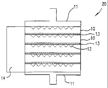
Fig. 2 is a schematic diagram showing a five fuel cell unit solid oxide fuel
cell
stack in accordance with one embodiment of this invention. Fuel cell stack 20
comprises a
plurality of integral component fuel cell units 10 with a thin, flexible metal
foil interconnect
13 disposed between adjacent fuel cell units 10. To provide fuel and oxidant
gases to the
respective fuel gas channels and oxidant gas channels, gas manifolds 14, only
one of which
is shown for simplicity, are in communication with fuel gas channels 18 and
oxidant gas
channels 12 to provide the requisite fuel gas to the porous anode 16 and
oxidant gas to the
porous cathode 15 of each integral component fuel cell unit 10 of solid oxide
fuel cell stack
20.
The use of a flexible metal foil as interconnect 13 in accordance with the
solid
oxide fuel cell stack of this invention provides many advantages over
traditional
interconnects. In particular, the use of a flexible metal foil facilitates
sealing between
interconnect 13 and each integral component fuel cell unit 10 under a slight
compressive
stress without the necessity of a glass seal. Because the foil interconnect is
metallic and thin,
some amount of plastic deformation readily occurs under compression, thereby
allowing for
good sealing. In addition, a flexible foil insures a good electrical contact
between the
integral component fuel units 10 and the interconnects 13. In accordance with
a particularly
preferred embodiment of this invention, the flexible metallic foil
interconnect has a thickness
in the range of about 1 mil to about 10 mils (25 microns - 250 microns). In
accordance with
a particularly preferred embodiment of this invention, the metallic foil
interconnect has a
thickness of about 5 mils.
Because there is no glass seal as in conventional solid oxide fuel cell
stacks,
the entire fuel cell stack of this invention is not a rigid mass, unlike a
glass-sealed stack. As
a result, the solid oxide fuel cell stack of this invention can be subjected
to rapid variations
in temperature without the fear of cracking due to thermal stresses. The
individual fuel cell
units are quite sturdy and are thermally shock resistant due to the presence
of a large amount
4
CA 02391487 2008-06-04
of nickel in the anode, the thickest part of the integral component fuel cell
unit. In addition,
because the interconnect is a flexible metallic foil which readily deforms,
thermal expansion
matching is not a requirement, in contrast to known designs which typically
use either a
ceramic interconnect or a thick metallic interconnect. Finally, thin metallic
foils suitable for
use in the solid oxide fuel cell stacks of this invention are made from
commercially available
alloys. These alloys are usually off-the-shelf items and are relatively
inexpensive.
In accordance with one preferred embodiment of this invention, the metallic
foil interconnects of this invention are constructed of a superalloy. A
superalloy is a metal
alloy resistant to high temperature and typically comprises nickel, iron,
chromium, and
manganese. Examples of superalloys suitable for use as interconnects in the
solid oxide fuel
cell stack of this invention include, but are not limited to, austenetic
stainless steel, InconelTM,
Haynes' alloys, and Hastealloys'.
In accordance with one preferred embodiment of this invention, the solid
oxide fuel cell stack comprises end plates 11 which function as current
collectors.
EXAMPLE
Cell Fabrication
NiO and 8 mol. % yttria-stabilized zirconia (YSZ) powders were mixed and
ball-milled in ethanol for 24 hours. After the well-mixed slurry was dried
under vacuum, the
powder was die-pressed using steel dies to create channels for a cross-flow
arrangement. The
amount of powder per plate was approximately 45 grams and the dimensions of
the as-
pressed cells were approximately 7 centimeters by 7 centimeters in lateral
directions and
4 mm in thickness (after uniaxial pressing). The plates were bisqued in air at
1000 C for one
hour. A slurry of YSZ in ethylene glycol was made containing 2 grams of YSZ
per 10 ml
of ethylene glycol. One side of each NiO+YSZ plate with cross-flow channels
was
subsequently painted with the YSZ paste. The plates were then sintered in air
at 1400 C for
two hours.
LSM (Lao.gSro 2MnO(3_x)) powder, using a mixture of MnOzi SrCO3 and La2O3,
was prepared by calcining in air at 1000 C for eight hours. YSZ powder was
also calcined
in air at 1200 C for one hour to coarsen the particle size. The calcined LSM
and YSZ
powders were mixed in equal amounts by weight to which ethanol was added. The
slurry
5
CA 02391487 2001-12-11
WO 00/77872 PCT/US00/16387
was subsequently ball-milled. After the powder mixture was dried, the powder
was mixed
in ethylene glycol in a ratio of 5 grams of LSM + YSZ to 5 ml of ethylene
glycol to make
a thick paste. The paste was applied on the YSZ-coated side of the sintered
plates and they
were heated at 400 C. This procedure was repeated until a LSM+YSZ cathode of
the desired
thickness, about 40-60 microns, was formed. Powder of LSM, without YSZ, in
ethanol was
ball-milled for 24 hours. After the powder mixture was dried, the LSM powder
was mixed
in ethylene glycol, 5 grams LSM to 5 ml ethylene glycol, to prepare a thick
paste. The paste
was applied on the LSM+YSZ painted plates and heated to about 160 C. The
procedure was
repeated until the desired thickness, about 150-200 microns, of LSM was
obtained.
Achieving a high enough thickness is important for minimizing the sheet
resistance. The
painted plates were heated in air to 1210 C for one hour. The maximum
thickness of the
cells, thickness varying due to the presence of grooves or channels, was about
3 mm.
Stack Testing
A stack was assembled using four integral component fuel cell units and
metallic (superalloy) interconnect foils. End plates, which served as current
collectors, were
also made of a superalloy. The diameter of the current collector rods (See
Fig. 2) was
1.27 centimeters. Three voltage probes were introduced, one each attached to
an
interconnect. The stack was secured inside a metallic manifold with mica
gaskets as edge
seals. In order to improve the sealing, the stack was spring-loaded wherein
the springs were
outside the hot zone of the furnace. The stack was tested at 800 C with
humidified hydrogen
as the fuel and air as the oxidant. Reduction of NiO to Ni was achieved in-
situ. The active
area of the cell was estimated to be between 75 and 80 cmz. Fig. 3 shows
voltage versus
current for the stack and Fig. 4 shows a plot of the total power versus
current. The maximum
power measured was approximately 33 watts. The area specific resistance of the
two inner
repeat units (cell-interconnect) was about 0.5 cm2. The end repeat units had
somewhat
higher area specific resistances due to a poor contact between the current
collectors and the
end cells.
While in the foregoing specification this invention has been described in
relation to certain preferred embodiments thereof, and many details have been
set forth for
purpose of illustration, it will be apparent to those skilled in the art that
the invention is
6
CA 02391487 2001-12-11
WO 00/77872 PCT/US00/16387
susceptible to additional embodiments and that certain of the details
described herein can be
varied considerably without departing from the basic principles of the
invention.
7