Language selection

Search

Patent 2392064 Summary

Third-party information liability

Some of the information on this Web page has been provided by external sources. The Government of Canada is not responsible for the accuracy, reliability or currency of the information supplied by external sources. Users wishing to rely upon this information should consult directly with the source of the information. Content provided by external sources is not subject to official languages, privacy and accessibility requirements.

Claims and Abstract availability

Any discrepancies in the text and image of the Claims and Abstract are due to differing posting times. Text of the Claims and Abstract are posted:

  • At the time the application is open to public inspection;
  • At the time of issue of the patent (grant).
(12) Patent Application: (11) CA 2392064
(54) English Title: LEAK DETECTION METHOD
(54) French Title: PROCEDE DE DETECTION DE FUITE
Status: Deemed Abandoned and Beyond the Period of Reinstatement - Pending Response to Notice of Disregarded Communication
Bibliographic Data
(51) International Patent Classification (IPC):
  • E21B 47/107 (2012.01)
(72) Inventors :
  • HEIJNEN, WILHELMUS HUBERTUS PAULUS MARIA
(73) Owners :
  • SHELL CANADA LIMITED
(71) Applicants :
  • SHELL CANADA LIMITED (Canada)
(74) Agent: SMART & BIGGAR LP
(74) Associate agent:
(45) Issued:
(86) PCT Filing Date: 2000-11-29
(87) Open to Public Inspection: 2001-06-07
Availability of licence: N/A
Dedicated to the Public: N/A
(25) Language of filing: English

Patent Cooperation Treaty (PCT): Yes
(86) PCT Filing Number: PCT/EP2000/012032
(87) International Publication Number: EP2000012032
(85) National Entry: 2002-05-17

(30) Application Priority Data:
Application No. Country/Territory Date
99309606.4 (European Patent Office (EPO)) 1999-11-30

Abstracts

English Abstract


The method comprises the steps of: a) passing a sonic tool (15) provided with
a transducer package (17, 18) capable of sending and receiving a sonic signal,
through the well tubular; b) prior to start of hydrocarbon fluid production
through the well, inducing the transducer package (17, 18) to transmit the
sonic signal through the well tubular (9) and to receive a reflected signal,
and making a primary registration of the reflected signal indicative of a leak-
free well tubular; c) after start of hydrocarbon fluid production through the
well, inducing the transducer package (17, 18) to transmit the sonic signal
through the well tubular (9) and to receive a reflected signal, and making a
secondary registration of the reflected signal indicative of an operational
well tubular; d) comparing the primary and secondary registrations and
detecting a leak in the well tubular from a difference between said
registrations.


French Abstract

Le procédé comprend les étapes suivantes: a) passage dans la colonne d'un outil (15) acoustique équipé d'un transducteur (17, 18) capable d'émettre et de recevoir un signal acoustique; b) avant le début de la production de flux fluides d'hydrocarbures dans le puits, préparation de l'ensemble /17, 18) transducteur à l'émission du signal acoustique dans la colonne (9) et à la réception du signal réfléchi, et premier enregistrement du signal réfléchi indiquant l'absence de toute fuite dans la colonne; c) après le début de ladite production dans le puits, préparation de l'ensemble (17, 18) transducteur à l'émission du signal acoustique dans la colonne (9) et à la réception du signal réfléchi, et second enregistrement du signal réfléchi indiquant l'état opérationnel de la colonne; d) comparaison entre les premier et second enregistrements et détection d'une fuite dans la colonne à partir de la comparaison.

Claims

Note: Claims are shown in the official language in which they were submitted.

-6-
CLAIMS
1. A method of detecting a leak in a well tubular of a
well for the production of hydrocarbon fluid from an
earth formation, the method comprising the steps of:
a) passing a sonic tool provided with a transducer
package capable of sending an receiving a sonic signal,
through the well tubular;
b) prior to start of hydrocarbon fluid production
through the well, inducing the transducer package to
transmit the sonic signal through the well tubular and to
receive a reflected signal, and making a primary
registration of the reflected signal indicative of a
leak-free well tubular;
c) after start of hydrocarbon fluid production through
the well, inducing the transducer package to transmit the
sonic signal through the well tubular and to receive a
reflected signal, and making a secondary registration of
the reflected signal indicative of an operational well
tubular;
d) comparing the primary and secondary registrations and
detecting a leak in the well tubular from a difference
between said registrations.
2. The method of claim 1, further comprising repeating
steps c) and d) at selected time intervals.
3. The method of claim 1 or 2, further comprising
locating the position of the leak
4. The method substantially as described hereinbefore
with reference to the drawing.

Description

Note: Descriptions are shown in the official language in which they were submitted.


CA 02392064 2002-05-17
WO 01/40627 PCT/EP00/12032
- 1 -
LEAK DETECTION METHOD
The present invention relates to a method of
detecting a leak in a well tubular of a well. The well
comprises a borehole lined with a well tubular that is
cemented into the borehole. The well can be a fluid-
s producing well or an injecting well.
It is often difficult to detect the presence of a
leak in the well tubular, and it is even more difficult
to determine the location of such a leak.
It is an object of the present invention to provide a
simple method to overcome this problem.
In accordance with the invention there is provided a
method of detecting a leak in a well tubular of a well
for the production of hydrocarbon fluid from an earth
formation, the method comprising the steps of:
a) passing a sonic tool provided with a transducer
package capable of sending an receiving a sonic signal,
through the well tubular;
b) prior to start of hydrocarbon fluid production
through the well, inducing the transducer package to
transmit the sonic signal through the well tubular and to
receive a reflected signal, and making a primary
registration of the reflected signal indicative of a
leak-free well tubular;
c) after start of hydrocarbon fluid production through
the well, inducing the transducer package to transmit the
sonic signal through the well tubular and to receive a
reflected signal, and making a secondary registration of
the reflected signal indicative of an operational well
tubular;
d) comparing the primary and secondary registrations and
detecting a leak in the well tubular from a difference

CA 02392064 2002-05-17
WO 01/40627 _ 2 - PCT/EP00/12032
between said registrations.
It is thus achieved that the primary registration
serves as a reference which represents the situation of
no leakage of fluids through the tubular. Any difference
between the later registration and the reference provides
an indication of the occurrence leakage through the well
tubular.
Reference is made to USA patent specification
No. 5 031 467. This publication discloses a method of
detecting fluid flow behind the casing that can be used
in the method of the present invention. Suitably, the
transducer package is packed in set of pads which are in
contact with the inner surface of the well tubular.
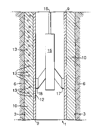
The invention will now be described in more detail
with reference to the accompanying drawing, which shows
schematically a cross-section of part of a well 1, which
can be a production or an injection well. The well 1
comprises a borehole 3 drilled into an underground
formation 6. The borehole 3 is lined with a well tubular
in the form of casing or a liner 9, and the annular space
between the outer surface of the casing 9 and the inner
surface of the borehole 3 is filled with cement 10.
During normal operation, fluid is transported through
the casing 9 to surface (not shown) in case of a
production well, or to an underground location (not
shown) in case of an injection well. When there is a leak
in the casing 9, fluid will escape into the cement-filled
annular space 10. Because the cement is porous, fluid
will migrate through the cement 10. In the drawing, the
leak in the casing 9 is referred to by means of reference
numeral 12, and the migrating fluid is shown as
bubbles 13. For the sake of clarity, not all bubbles have
been referred to with a reference numeral.
In order to detect the presence of a leak in the
casing 9, a sonic tool 15 suspended from a cable or a

CA 02392064 2002-05-17
WO 01/40627 PCT/EP00/12032
- 3 -
pipe 16 is lowered into the casing 9. The sonic tool 15
comprises two or more pads containing each a transducer
package shown as numeral 17 and 18, which pads are during
normal operation in contact with the inner surface of the
well tubular 9. The transducer packages 17, 18 comprise
separate transmitting and receiving transducers (not
shown). During normal operation the transmitter
transducers generate a high-frequency pulsed beam of
acoustic energy and the reflections are received by the
receiving transducers. Differences between a pair of
received reflections will be an indication of fluid flow
behind the well tubular 9 (assuming no other changes).
The sonic tool 15 is electronically connected by means of
an electrical cable to the read-out unit at surface (not
shown) to make a registration of the signals from the
transducer packages 17 and 18 allowing interpretation of
the signals at surface. The registration of the received
signals forms an acoustic signature of the well tubular,
and it can be used to detect fluid flow behind the well
tubular 9.
The fluid 13 migrating through the cement 10 will be
detected by the transducer packages as described in USA
patent 5 031 467. When having installed and cemented the
casing 9 the sonic tool 15 is run and operated to make a
registration indicative of a leak-free well tubular, and
it is kept for future reference so that there is no
misinterpretation in the later life time of the well. The
registration is an acoustic signature of a leak-free well
tubular. Subsequent runs are made during the life time of
the well to detect possible flow behind the well
tubular 9 due to cross-flow between two earth formations.
Together with other registrations it can be used to
determine whether there is cross-flow and how this
develops.

CA 02392064 2002-05-17
WO 01/40627 PCT/EP00/12032
- 4 -
Whenever the scenic tool 15 is being run later it will
be run in the following manner. The sonic tool 15 is
lowered to the bot~:~om of wellbore 1 and the pads 17 and
18 are then brought into contact with the inside of the
casing 9. The sonic tool 15 is then pulled up and
whenever it passes a position were a leak in the casing 9
has developed the read-out at surface will detect leakage
of well fluids into the cement 10. The position of the
leak is then the position of the sonic tool 15 at the
time a leak was detected. The registration so obtained is
an acoustic signature of a leaking well tubular.
It is not always the case that production is done
through the casing 9: in many cases, production takes
place through a well tubular in the from of a well tubing
that is suspended into the well from surface to the
fluid-bearing formation. The annular space between the
outer surface of the well tubing and the inner surface of
the casing is filled with a liquid (either a drilling mud
or a completion fluid). During normal operation, fluid is
produced from the fluid-bearing formation. The fluid is
transported through the well tubing to surface. When
there is a leak in the well tubing, fluid will escape
into the liquid in the annular space between the well
tubing and the casing, and fluid will thereby migrate
through the annular fluid. In order to determine whether
there is a leak in the well tubing, a sonic tool as
described above is lowered into the well tubing. At
surface a registration is made of the signals received
from the sonic transducer of the sonic tool and the
registrations are compared with a registration indicative
of a leak-free well tubular so as to detect the presence
of a leak. The location of the leak is then the depth
along the borehole of the sonic logging tool.
Alternatively, at regular time intervals the sonic
tool is run into the fluid-producing well, and each time

CA 02392064 2002-05-17
WO 01/40627 - 5 - PCT/EP00/12032
the registration is compared with a previous
registration. The registration indicative of a leak-free
well tubular then is the previous registration.
The invention has been described with reference to
fluid leaking out of the interior of the well tubular
into the space behind it, however, the method of the
present invention can as well be applied in case the
fluid leaks from outside the well tubular into it.
The method of the present invention can also be used
to determine the quality the cement bond between well
tubular and cement, and for determining the movement of
earth formations.
The invention provides a simple method of detecting
leaks in a fluid-producing well, wherein a sonic tool is
used in an active mode.

Representative Drawing
A single figure which represents the drawing illustrating the invention.
Administrative Status

2024-08-01:As part of the Next Generation Patents (NGP) transition, the Canadian Patents Database (CPD) now contains a more detailed Event History, which replicates the Event Log of our new back-office solution.

Please note that "Inactive:" events refers to events no longer in use in our new back-office solution.

For a clearer understanding of the status of the application/patent presented on this page, the site Disclaimer , as well as the definitions for Patent , Event History , Maintenance Fee  and Payment History  should be consulted.

Event History

Description Date
Inactive: IPC deactivated 2016-03-12
Inactive: First IPC assigned 2016-01-29
Inactive: IPC assigned 2016-01-29
Inactive: IPC expired 2012-01-01
Time Limit for Reversal Expired 2005-11-29
Application Not Reinstated by Deadline 2005-11-29
Deemed Abandoned - Failure to Respond to Maintenance Fee Notice 2004-11-29
Inactive: Cover page published 2002-10-25
Inactive: Notice - National entry - No RFE 2002-10-23
Letter Sent 2002-10-23
Inactive: Applicant deleted 2002-10-23
Application Received - PCT 2002-08-19
National Entry Requirements Determined Compliant 2002-05-17
Application Published (Open to Public Inspection) 2001-06-07

Abandonment History

Abandonment Date Reason Reinstatement Date
2004-11-29

Maintenance Fee

The last payment was received on 2003-09-05

Note : If the full payment has not been received on or before the date indicated, a further fee may be required which may be one of the following

  • the reinstatement fee;
  • the late payment fee; or
  • additional fee to reverse deemed expiry.

Patent fees are adjusted on the 1st of January every year. The amounts above are the current amounts if received by December 31 of the current year.
Please refer to the CIPO Patent Fees web page to see all current fee amounts.

Fee History

Fee Type Anniversary Year Due Date Paid Date
Basic national fee - standard 2002-05-17
Registration of a document 2002-05-17
MF (application, 2nd anniv.) - standard 02 2002-11-29 2002-10-03
MF (application, 3rd anniv.) - standard 03 2003-12-01 2003-09-05
Owners on Record

Note: Records showing the ownership history in alphabetical order.

Current Owners on Record
SHELL CANADA LIMITED
Past Owners on Record
WILHELMUS HUBERTUS PAULUS MARIA HEIJNEN
Past Owners that do not appear in the "Owners on Record" listing will appear in other documentation within the application.
Documents

To view selected files, please enter reCAPTCHA code :


To view images, click a link in the Document Description column (Temporarily unavailable). To download the documents, select one or more checkboxes in the first column and then click the "Download Selected in PDF format (Zip Archive)" or the "Download Selected as Single PDF" button.

List of published and non-published patent-specific documents on the CPD .

If you have any difficulty accessing content, you can call the Client Service Centre at 1-866-997-1936 or send them an e-mail at CIPO Client Service Centre.

({010=All Documents, 020=As Filed, 030=As Open to Public Inspection, 040=At Issuance, 050=Examination, 060=Incoming Correspondence, 070=Miscellaneous, 080=Outgoing Correspondence, 090=Payment})


Document
Description 
Date
(yyyy-mm-dd) 
Number of pages   Size of Image (KB) 
Representative drawing 2002-05-16 1 21
Abstract 2002-05-16 2 77
Claims 2002-05-16 1 32
Drawings 2002-05-16 1 23
Description 2002-05-16 5 188
Notice of National Entry 2002-10-22 1 192
Courtesy - Certificate of registration (related document(s)) 2002-10-22 1 109
Courtesy - Abandonment Letter (Maintenance Fee) 2005-01-23 1 175
Reminder - Request for Examination 2005-07-31 1 115
PCT 2002-05-16 7 243
PCT 2002-05-16 1 72