Note: Descriptions are shown in the official language in which they were submitted.
CA 02392667 2002-07-05
-1_
METHOD FOR REGIONAL SYSTEM WIDE OPTIMAL SIGNAL TIMING
FOR TRAFFIC CONTROL BASED ON WIRELESS PHONE NETWORKS
s FIELD OF THE INVENTION
This invention relates generally to traffic control systems. More
specifically, the present invention relates to a traffic control system that
optimizes
traffic flow based on information obtained via a wireless telephone network.
BACKGROUND OF THE INVENTION
io Optimization of Traffic Signal Timings in Regional Traffic Control Systems
Problems in traffic control have been studied extensively over the
last few decades. Conventional traffic control systems comprise three major
components: hardware infrastructure, information gathering systems, and
traffic
control software including mathematical models and algorithms. At present we
are
15 primarily interested in software models and algorithms, and in information
gathering systems.
CA 02392667 2002-07-05
-2-
Existing Methods of Gathering Information on Traffic Conditions
Due to ever increasing traffic volume, traffic control and information
acquisition have become an important part of the overall traffic management
strategy.
s Generally, dynamic traffic data are gathered by three methods:
1. Road sensor devices such as induction loops, traffic detectors,
and TV cameras mounted on poles;
2. Mobile traffic units such as police, road service, helicopters,
weather reporting devices, etc.
3. Mobile positioning and communication systems using GPS
devices or similar vehicle-tracking equipment.
The disadvantages of these data collection methods are summarized
as follows:
1. Relatively high cost of required capital investment into road
Is devices especially when carried out within existing road
infrastructures;
2. Relatively limited number of organizations such as trucking,
delivery and other service companies utilizing reporting
vehicles equipped with GPS devices;
3. In general only small geographical areas are effectively
covered due to specific nature of service tasks, apart from the
relatively small number of cars equipped with required GPS
devices necessary for precise position determination.
In a recent development, GPS reporting devices have been mounted
on individual cars to provide positioning information of vehicles via wireless
mobile communication systems. The additional expenditures required by these
CA 02392667 2002-07-05
-3-
mobile systems are much lower than by the traditional methods using fixed road
metering. One disadvantage of these systems is in the relatively limited
number of
cars equipped with required GPS devices necessary for precise position
determination, and therefore relatively small geographical areas that can be
effectively covered.
Modes of Operation of Traffic Control Systems
As originally coined, the term "traffic control" implied a human
operator, i.e. a policeman, or a specially trained dispatcher who directed
traffic
io flows across road intersections. This "controller" used his experience and
intuition
to evaluate traffic loads and waiting times in various directions and lanes,
and for
changing phase timing accordingly.
Following the introduction of electric traffic signals at the beginning
of the twentieth century, progress in the methods of traffic control closely
followed
is that of the control technology, and subsequently the progress of computer
science.
Initially, simple electric clocks allocated a specific amount of time to
each phase in a specific pattern to controlled traffic signals. These early
clock
systems were preset and provided no adjustment for peak traffic periods, or
for
unusual conditions.
20 The next step was to create a clock that operated differently at
different times of the day, and used several different control patterns for
different
times of day. Those patterns were determined from historical data.
Starting in the mid-1960's, computers were increasingly utilized in
traffic control. These computers made it possible to create actuated
controllers
25 that had the ability to adjust the signal phase lengths in response to
traffic flow in
real time. If no vehicles were detected on an approach to an intersection, the
controller could skip that phase or reduce the phase to a fixed minimum time.
CA 02392667 2002-07-05
-4-
Thus, the green time for each approach was a function of the traffic flow, and
could be varied between minimum and maximum lengths depending on traffic
flows.
Modes of operation of modem traffic control systems can be divided
into three primary categories: 1) pre-timed; 2) actuated (including both semi-
actuated and fully actuated); and 3) traffic responsive. Under pre-timed
operation,
the master controller sets signal phases and cycle lengths on predetermined
rates
based on historical data.
An actuated controller operates based on traffic demands as
registered by the actuation of vehicle and/or pedestrian detectors. There are
several types of actuated controllers, but their main feature is the ability
to adjust
the phases in response to traffic flow.
A semi actuated controller maintains green on the major street except
when vehicles are registered on minor streets, and then always return the
right of
way to the major street.
A fully actuated controller measures traffic flow on all approaches
and makes assignments of the right of way in accordance with traffic demands.
As
such, a fully actuated controller requires placement of detectors on all
approaches
to the intersection. Thereby increasing installation and maintenance costs
considerably.
In the traffic responsive mode, the system responds to inputs from
traffic detectors and may react in one of the following ways:
= Use vehicle volume data as measured by traffic detectors;
= Perform pattern matching - the volume and occupancy data
from system detectors are compared with profiles in memory,
and the most closely matching profile is used for decision
making;
CA 02392667 2002-07-05
-5-
Perform future traffic prediction - projections of future
conditions are computed based on data from traffic detectors.
Control Algorithms for Optimization of Timings for Traffic Signals
A number of algorithms exist that purport to optimize performance
of traffic responsive controllers that make use of various techniques such as
linear
programming, dynamic programming, fuzzy logic, regression analysis, and
optimization and prediction procedures. The objective function that is usually
set
up to be optimized is some measure of overall traffic delay at an intersection
or at
a number of intersections, while the major control parameter for achieving
this is
to the distribution of green and red light timings among different phases.
The usual framework for those algorithms is as follows. Signal
timings should reflect the number of vehicles present on each approach to an
intersection and the pattern of arrivals in the near future. The current queue
lengths on each approach are identified by locating slow-moving and stationary
is traffic close to the stop-line. Algorithms minimize the total delay subject
to certain
constraints. Such constraints are:
1. Adequate capacity for all allowed traffic movements; and
2. Safety constraints (minimum number of seconds for green and
inter-green times).
20 Minimization is performed over the pre-selected planning time
horizon, which limits the forward time interval for which computations are
made.
As optimization is performed continuously, we have a rolling horizon
framework.
The rate of delay on an approach is estimated as proportional to the
number of vehicles in the queue. Accordingly, the total rate of delay at the
25 intersection is the sum over all streams of these rates of delay. The
objective
function for optimization is the sum of those total rates of delay over the
planning
time period, which represents the total delay incurred. A slightly different
formulation of the objective of optimization is minimization of the weighted
sum
CA 02392667 2009-10-23
-6-
of the estimated rate of delay and the number of stops per unit time for all
traffic
streams. In such a formulation the problem is amenable to treatment by
mathematical optimization methods. In particular, by dynamic programming
and linear programming techniques.
Most conventional attempts for real time responsive control are
either optimized on a per intersection basis or make highly restrictive
simplifying assumptions in treating multiple intersection problems. Still,
there
are a few works treating area-wide traffic control optimization problems. For
example, U.S. Patent No. 5,668,717 issued to James C. Spall proposed the use
of
neural networks that are able to learn patterns of traffic situations, store
them for
future use and modify them when the traffic situation changes.
It appears, though, that at the present time no widely accepted and
approved method exists for optimizing traffic control signals on an area wide
scale.
SUMMARY OF THE INVENTION
In view of the shortcomings of the prior art, it is an object of an
aspect of the invention to provide a system and method for optimizing traffic
flow based on information received from wireless telephone systems.
The above-identified disadvantages of the prior art systems may be
overcome by using wireless networks as the sole means to provide location
information. Technologically, this may be achieved by measuring the distances
the signals traveling between a moving wireless (cellular) phone and a fixed
set
of base stations, and the times these signals take to travel. This information
may
then be applied to mathematical and statistical methods to solve the resulting
equations.
This exemplary approach takes advantage of improved accuracy of
measurement methods and of the large pool of wireless handsets that exist. For
example, in the United States alone there are presently about 50 million such
CA 02392667 2002-07-05
-7-
handsets. Furthermore, any necessary modifications, such as specialized
location
equipment, can be made on the network rather than on the handsets.
The present invention utilizes a cell phone network in which the data
from moving vehicles are collected continuously and input into the system. The
exemplary system filters and cleans the data by applying intelligent heuristic
algorithms and produces accurate real time information on traffic situations
that, in
turn, can be supplied to automated traffic controllers. This eliminates the
need for
developing a dedicated mobile wireless information gathering fleet and other
high
cost devices requiring large capital investments and considerable work force.
Network system wide control is the means for real time adjustment
of the timings of all signals in a traffic network to achieve a reduction in
overall
congestion consistent with the chosen system wide measure of effectiveness.
This
real time control is preferably responsive to instantaneous changes in traffic
conditions including changes due to various traffic incidents. Also, the
system is
is preferably adaptive in order to reflect daily and hourly non-recurring
events, such
as unexpected traffic pattern changes, temporary lane closures, etc., as well
as
long-term evolution in transportation systems like seasonal effects, permanent
road
changes, infrastructure development, etc. To achieve system wide optimization,
the timings at different signalized intersections will not, in general, have
predetermined relationships to one another except possibly for those signals
along
transportation arteries, where it will be preferable to synchronize the
intersections.
The present invention utilizes an intelligent data gathering and
processing system based on information flow from existing cellular phone
networks, and uses such obtained cell phone based position data for real time
computation of adjusted phase timings at signalized intersections.
The system of the present invention is capable of constructing and
maintaining lists of vehicles moving along road sections at particular periods
of
time. This is achieved by tracking a predetermined number of in-vehicle cell
phones within a given region. The exemplary system maintains a series of such
lists associated with the previous elapsed time period and calculates
estimates of
the numbers of vehicles traveling on each particular road section, their
actual
CA 02392667 2009-10-23
-8-
traveling times, and the turning times and go-through times for all signalized
intersections. Thus, the exemplary system is able to (1) compute real time
traffic loads for various roads and road sections, (2) generate
detailed lists and descriptions of vehicle turning movements, (3) compute
real time turning data for all relevant intersections, and (4) estimate other
relevant traffic parameters. The resulting information setup (with
numerous relevant parameters estimated on the basis of observations) is
then transferred with minimum delay to the automated traffic control system
for the purpose of adjusting phase timings at signalized intersections for the
next control time period. In other words, based on the traffic flow data
obtained for the previous control time period, the system attempts to adjust
phase timing at signalized intersections in such a way as to provide more
green time for more heavy traffic flows at the expense of less loaded
roadways for the next control time period. Roughly speaking, the longer
travel time has been registered at a particular turn during the previous
control time period, the more green light the intersection is going to get at
the
next time period.
This result may be achieved by maximizing a linear function in
green light timings the coefficients of which are functions of time delays
affected at all road sections during the previous control time period within
the
given region. Optimization is achieved under certain constraints, such as
minimal and maximal values of green light timings, safety constraints
expressing minimum number of seconds for inter-green times at each
intersection, and other relevant constraints which could be set up
individually
for any turn and go-through of any signalized intersection, etc. The new
values
of green light timings obtained from the optimization will he applied to the
next
control time period during which new measurements of traffic travel times
and traffic flows will be made as before, and the whole process will he
repeated.
Accordingly, in one aspect there is provided a method for
controlling and adjusting phase timings at all signalized intersections within
a
given geographical region with the purpose of allocating more green light time
CA 02392667 2009-10-23
- 8a-
for roads with heavier traffic flows at the expense of less loaded roadways
comprising the steps of:
(a) acquiring of dynamic traffic information from a cellular network
provider or a group of cellular network providers and from GPS based
technology whenever available for the purpose of monitoring movements of as
many traveling vehicles in a given region as possible;
(b) continuously or periodically obtaining location data on a plurality
of cell phones in a regional network in a specific real time frame;
(c) determining for each particular cell phone whether the cell phone
to is located in a traveling vehicle;
(d) setting up a list of all cell phones currently identified as located in
traveling vehicles;
(e) compiling and updating a sequence of real time positions of each
cell phone located in a traveling vehicle;
(f) positioning each cell phone located in a traveling vehicle onto an
appropriate road section at each particular moment according to its
coordinates;
(g) eliminating untenable cell phone positions by analyzing series of
recently recorded positions and relating them to nearby road sections;
(h) making imputations for missing cell phone positions by analyzing
series of recently recorded positions and relating them to nearby road
sections;
(i) calculating feasible continuous paths for all cell phones located in
traveling vehicles within a given time period;
(j) identifying multiple cell phones in a common vehicle and
combining them into a single vehicular cluster entity based on closely located
positions at corresponding time moments and common direction of movement;
(k) calculating feasible continuous paths for vehicular clusters within a
given time period; and
(1) storing the relevant position data for each individual vehicle or
vehicular cluster traveling along a given road section in the database for the
purpose of maintaining vehicle recent path information.
CA 02392667 2009-10-23
- 8b -
According to another aspect there is provided a method for
controlling at least one intersection within a predetermined geographical
region
having a plurality of road sections for use with at least one wireless
telephone
network, the method comprising the steps of-
(a) acquiring dynamic traffic information of a plurality of vehicles
from the at least one wireless telephone network;
(b) estimating a respective path for each of the plurality of vehicles;
(c) storing respective position data in a database for each of the
plurality of vehicles traveling along each road section of a plurality of road
to sections within a predetermined geographical region; and
(d) controlling a respective phase timing of at least one intersection
based on the corresponding position data of step (c).
CA 02392667 2002-07-05
-9-
BRIEF DESCRIPTION OF THE DRAWINGS
The invention is best understood from the following detailed
description when read in connection with the accompanying drawing. It is
emphasized that, according to common practice, the various features of the
drawing are not to scale. On the contrary, the dimensions of the various
features
are arbitrarily expanded or reduced for clarity. Included in the drawing are
the
following Figures:
Figure 1 is a flowchart representation of the traffic control system for
an exemplary embodiment of the present invention;
Figures 2A-2B are a detailed flowchart of Step 102 shown in Figure
1;
Figure 3 is a example of measured positions of a cell phone in a
vehicle moving along a road section;
Figure 4 is an example of outlying vehicle positions in the vicinity of
is an intersection.;
Figure 5 is an exemplary intersection of two two-way roads;
Figure 6 is a topologically equivalent detailed map of the intersection
shown in Figure 5; and
Figure 7 is an estimation of actual travel times for various portion of
the intersection shown in Figure 6.
DETAILED DESCRIPTION OF THE INVENTION
One purpose of the present invention is to optimize the phase timings
at signalized intersections in such a way as to relieve the most jammed
portions of
CA 02392667 2002-07-05
-10-
the network at the expense of its less loaded portions. In an exemplary
embodiment of the present invention, this may be achieved by collecting
location
data from the maximum possible number of vehicles moving in a given region,
estimating of traffic loads on all road sections and turns, and then by
adjusting
phase timings to ease the most congested roadways.
Naturally, the extent and the precision of the overall data collected
from the plurality of cell phones in the given network will largely depend on
the
total number of current cell phone users as well as on the technology used for
measuring and recording the data. It should be noted here that for purposes of
the
io present invention, data collection is based on any cell phone in an "on!
'position,
and as such will be considered part of the reporting system.
The present invention does not deal with problems related to the
precision of the cell phone location methods, but rather presumes existing
cell
phone location technologies and anticipates their progressive improvement in
the
future. It is also assumed that increasing competition in the cell phone
market will
further enhance the already large popularity of cell phone usage by the
public.
In the exemplary system, all relevant cell phone position data will be
obtained directly from the cell phone network operator without any involvement
of
the individual phone user. After receiving all location data, the system
proceeds to
compute travel times for all road sections and turns, and optimizes the phase
timings accordingly.
Figures 1-3 are a representation of the exemplary cell phone
gathering system. The following main steps of data exchange flow are described
in detail below.
1. Overview of Control Scheme and of Computational Method
2. Obtaining Cell Phone Records From the Network Operator
3. Creating and Storing the Current and Previous Cell Phone
Lists
4. Creating Preliminary Cell Phone Path Profiles
5. Cleaning the Data
CA 02392667 2002-07-05
-11-
6. Discrimination Between Phones in Moving Vehicles and
Other Phones
7. Grouping Cell Phones Into Vehicular Clusters
8. Theoretical Travel Times for Turns and Go-throughs
s 9. Actual Travel Times for Road Sections, Turns and Go-
throughs
10. Maximization of Objective Function F, Computation of
Resulting Phase Timings, and Applying Them for The Next
Control Period
to 11. Future Embodiments And Additional Applications
Overview of Control Scheme and of Computational Method
As indicated above, the exemplary system and method uses traffic
data obtained during the previous control time period T, for adjusting phase
timings at signalized intersections at the next control time period T,+, in
such a
15 way as to provide more green light time for more heavy traffic flows at the
expense of less loaded roadways. This is achieved by maximizing a linear
function Fin green light timings G.
FW;~G0
+,i
where, i indexes signalized intersections within the given region, j runs over
the
20 green lights at intersection i, and coefficients W;; measure time delays
resulting
from traffic congestions.
The new values of green light timings G. resulting from the
optimization of F will be applied to the control period Ts.,, during which new
measurements of traffic delays will be made as before, and the whole process
will
25 be repeated.
To compute the values of G., we will perform the maximization of
F above under the system of constraints
Giy,mm < GY 5 Gy.max
CA 02392667 2002-07-05
-12-
and
G,,,,,;. <_ G 5 G;,õ,aõ
where computation of weights W, will be explained below, the constants G,,,,,,
G;u,.., G;,,n;,, and G; ,,,aX are assumed known, and i and j are as defined
above.
s Apart from the listed constraints, the minimization problem may
contain other relevant constraints, such as safety constraints expressing
minimum
number of seconds for inter-green times at each intersection. As their
structure is
quite similar to the listed above constraints, however, we will not try to
enumerate
all of them explicitly, and will presume they have been included into the
system of
to constraints above.
Maximization of F can be performed by standard linear
programming techniques.
Computation of Weights W;,
For maximization of F we need to know the weights W,. These
15 weights indicate an increase in waiting times resulting from traffic
congestion at
the corresponding intersections.
The weights Wk are computed where, k is the index number of turn
at the intersection i controlled by the green light j. The weights Wyk are
computed by the formula
20 Wlk = tOk /Tjk
where, t,k is an average actual travel time for the turn k averaged over a
number
of vehicles that made that turn during the previous time period, and Tyk is
the
theoretical (regular) travel time for that turn.
CA 02392667 2002-07-05
-13-
The travel times tfk will be called actual travel times, and the travel
times T jk the theoretical travel times. Now, the weights W, are computed by
the
formula
Wj Wjk
k
and substituting them into the function F, we can perform optimization as
described above and compute the corresponding green light timings G, .
Obtaining Cell Phone Records from the Network Operator
It is assumed that the cell phone network operator is capable of
providing all the necessary information on the plurality of active cell phone
units
in the network. The process of collecting and transmitting cell phone position
data
is well known to those skilled in the art and described in the literature.
For the purposes of the present invention it is contemplated that the
data are received in the form of periodic data packets in real time, such as
every 1
to 3 minutes, for example. The exemplary packet file consists of a list of
records,
is each for a single cell phone, containing the phone's unique ID number, the
recorded time of signal reception t, and its location P (x, y):
record(CP) = (ID, t, x, y)
For the purposes of protecting privacy of individual cell phone users,
an automatic coding system set up by the network operator will assign to each
cell
phone number a unique ID reference number. In the exemplary embodiment of the
present invention, only the reference ID will be used to identify each cell
phone
record.
Creating And Storing the Current And Previous Cell Phone Lists
At each time period T,, the Traffic Control System compiles a
current phone list consisting of cell phone records (in the sense defined
above) of
all available active cell phones in a system database ordered by their ID
reference
CA 02392667 2002-07-05
-14-
numbers. At the next control period T,., , a new current phone list is
compiled and
recorded similarly, with the first current phone list becoming the previous
phone
list number 1. At the following control period, a new current phone list is
compiled, the current phone list becomes the previous phone list number 1, and
the
previous phone list number 1 becomes the previous phone list number 2, etc.
For
the purposes of analysis, it may be necessary to store at any given moment a
predetermined number of those lists, such as, 4 or 5 for example.
Creating Preliminary Cell Phone Path Profiles
To track moving vehicles, it will be convenient to create a temporary
io cell phone path profile for each active cell phone in a given area and to
place
individual cell phone positions onto the digital map. The exemplary map
database
contains a list of all road sections, each with a number of fixed attributes
such as
road name, the names of two adjacent intersection nodes, permissible speed,
number of lanes, turns to and from the nodes, sensor devices if available,
automatic traffic control signals, and all other pertinent data. For each
individual
cell phone, we define its original path profile as a series of its database
records, i.e.
initial location measurements. The path profile for a cell phone can only be
constructed if the re-determined number of its latest recorded positions is
available.
Figure 3 illustrates a cell phone path profile along road section 300
based on positions 302, 304, 306, 308, 310 of a cell phone (not shown). Note
that
due to measurement errors those recorded cell phone positions will generally
not
lay on the road the vehicle traveled by, but rather in the vicinity of it. To
correct
for this, the Positioning Algorithm disclosed in co-pending patent application
no.
09/xxxxxx, filed July 10, 2001 and assigned to the same assignee as the
present
invention, may be used for finding most likely positions of cell phones on
road
sections. This co-pending application is entitled "Traffic Information
Gathering
via Cellular Phone Networks for Intelligent Transportation Systems" and is
incorporated herein by reference. In brief, the Positioning Algorithm works as
follows. Given a point P' (recorded cell phone position), the Positioning
Algorithm searches for a point P nearest to point P' located on one of the
closest
CA 02392667 2002-07-05
- 15-
road sections. Such a point is deemed to be the most probable position of the
cell
phone.
After all recorded cell phone positions have been adjusted and
associated with individual road sections, the adjusted phone list is created
with all
s cell phones placed on road sections.
For some computations required by the traffic model, continuous
paths will be used as travel routes rather than lists of cell phone positions.
Construction of such continuous path profiles can be achieved by simple
interpolation and extrapolation techniques, in particular by constructing
linear
regression curves. It is assumed that valid interpolations and extrapolations
can be
performed within the given road section.
Even with less than predetermined number of recorded positions,
linear regression or interpolation may still be performed although precision
may
suffer. On the other hand, one should be warned again attempting extrapolation
is over section boundaries. It appears that while the assumption of validity
of
interpolation and extrapolation within a common road section is tenable,
extrapolating across section boundaries is not recommended. This is due to
abrupt
changes in speed that often occur while switching between sections, long
waiting
times near intersections, possible congestion at section ends, sudden stops
that
drivers make before entering highways, various turning point delays, etc.
Cleaning the Data
A continuous cell phone path profile constructed by means of the
Positioning Algorithm and interpolations and extrapolations may not always be
satisfactory. As a matter of fact, due to large measurement errors and the
closeness of road sections to one another, especially in dense urban areas, it
may
occur that outliers, i. e. untenable cell phone positions, have been included
into the
path profile.
CA 02392667 2002-07-05
-16-
Figure 4 is an example of outlying vehicle positions in the vicinity of
intersection 414. In the series of vehicle positions 402, 404, 406, 408, 410
shown
in Figure 4, positions 408, 410 are outliers. Line 412 illustrates the path
taken by
the subject vehicle.
For the process of construction of continuous cell phone path
profiles, outlying positions (408, 410 shown in Figure 4) are misleading
records
that may severely impair or invalidate the continuous cell phone path, which
has
been influenced by it. Therefore, it is requisite to use statistical
procedures for
filtering or cleaning the data prior to cell phone path construction, or after
attempting path construction. In any case, before proceeding to the following
computations, the observed cell phone positions should be checked for validity
and
consistency. Furthermore, if some observable cell phone positions are missing
due
to technical errors or other reasons, statistical procedures for treating
missing
observations should be applied. Examples of such procedures can be found in
the
is co-pending patent application referred to above (Traffic Information
Gathering via
Cellular Phone Networks for Intelligent Transportation Systems).
Discrimination Between Phones In Moving Vehicles And Other Phones
Once the list of all cell phone profiles has been set up, it should be
analyzed as to which phones are located in traveling vehicles and which are
not.
In fact, phones located in traveling vehicles usually possess some attributes
not
found with other phones. As a result, some of these attributes can be used for
separating phones located in moving vehicles, on the one hand, and all other
phones on the other. Among those other phones may be stationary phones, such
as
phones inside houses, phones left in parked cars, slowly moving phones such as
phones held by pedestrians, fast moving phones located in trains, held by
bicycle
and motorcycle riders which may be moving in the open without regard to any
roads, and probably many other cases difficult to envision and enumerate.
Roughly speaking, phones moving along discernible roads with speeds that, at
least part of the time, are significantly greater than speeds of pedestrians
should be
classified as phones in moving vehicles. A formal and detailed discriminating
procedure for performing this task may be found in aforementioned co-pending
CA 02392667 2002-07-05
-17-
patent application (Traffic Information Gathering via Cellular Phone Networks
for
Intelligent Transportation Systems).
GroupingCell Phones Into Vehicular Clusters
After the phones travelling in moving vehicles have been identified
with a minimum number of errors, it is necessary to identify and eliminate the
possibility that two or more cell phones traveling in a single vehicle will
mistakenly be recorded as two or more moving vehicles. If this is allowed to
happen, it will lead to misrepresenting the actual number of moving vehicles
or the
"vehicular load" on a particular road section and to distortion of general
picture
i0 representing the traffic situation at the given moment.
In our co-pending patent application (Traffic Information Gathering
via Cellular Phone Networks for Intelligent Transportation Systems),
procedures
for 1) grouping moving phones into vehicular clusters, 2) positioning thus
constructed vehicular clusters onto roads, and 3) constructing continuous path
is profiles for them are described. The net result is a list of vehicular
clusters moving
along particular roads in a given time period.
Theoretical Travel Times for Turns and Go-throughs
As indicated in the first section Overview of Control Scheme and of
Computational Method, the weights Wyk were computed by the formula
20 Wyk = tUk'Tjk
where, tYk are actual travel times, and Tk are theoretical travel times.
Actual travel times for turns and go-throughs include waiting due to
congestion conditions, while theoretical travel times do not.
First, theoretical travel times Tok are computed, and in the next
25 section a method for estimating actual travel times t;;k is described.
CA 02392667 2002-07-05
- 18-
Let t,. denote the time during which the red light is on, and similarly
tg the time for a green light. Denote by E(tõ,;, I red) the mathematical
expectation
of the waiting time if the driver arrived to the intersection when the red
light was
on, and similarly EQ.,, I green) for green. Also denote by Pr(red) the
probability
s that the red light is on when the driver arrives at the intersection, and
similarly
Pr(green) the probability of the green light. Now, the expectation of the
waiting
time can be computed by the total probability formula:
Etmõ = EQ.,, I red) Pr(red) + E(twa,, ' green) Pr(green)
Since E(t,w,,, I green) = 0, this simplifies to
Etw,,, = E(t., ( red) Pr(red)
It is easily seen that E(t,,Qõ I red) = tr / 2, and Pr(red) = tr /(tg + tr)
resulting in:
Etõaõ = t; /(2(tg + tr ))
This formula gives the mean waiting time of the driver arriving at an
intersection
is under ideal traffic conditions with no congestion and no delays whatsoever.
Actual Travel Times for Road Sections, Turns and Go-throughs
In this section a method for estimating actual travel times t#k for
turns and go-throughs is described. First, however, some definitions are
necessary.
For computing actual travel times for traveling across a road
network, it is convenient to represent each two-way road section as a pair of
one-
way sections. Also, as each road intersection contains a number of changeovers
(turns and go-throughs) from one section to another, it will be useful to
represent
each such changeover from an incoming section to an outgoing section by a new
abstract transition segment possessing its own travel time.
CA 02392667 2002-07-05
-19-
Figure 5 shows a rather simple example of an intersection of two
two-sided roads. The intersection itself is marked by to , and the neighboring
intersections are denoted I, , I2 , I3 and I4 .
Section S10 goes from intersection I, to intersection Io, section So,
goes from intersection Io to intersection I,, section S02 goes from
intersection to
to intersection I2 , etc., so that we have 8 separate one-sided road sections.
All the turns and pass-throughs at Io are permissible except for two
left turns: the turn from S10 to S02 (502) and the turn from S30 to Soo (504)
are not
allowed.
A topologically equivalent detailed map of the intersection area in
Figure 5 is shown in Figure 6. In Figure 6, all two-sided sections are shown
as
pairs (I1, 12, 13, 14) of one-sided sections with travel directions indicated
by arrows
(SO1, S10, S02) S205S039 S30, S04, S40). Permissible turns (602, 604, 606,
608, 610,
612) and go-throughs (614, 616, 618, 620) are also shown by arrows so that,
e.g.,
the incoming section S10 is followed by two arrows connecting it to the
outgoing
section S04 (right turn) and to the outgoing section S03 (go-through).
Similarly,
the incoming section S40 is followed by three arrows connecting it to the
outgoing
section So, (left turn), to the outgoing section S02 (go-through) and to the
outgoing
section S03 (right turn). In total, there are 10 additional transition
segments, i. e.
permissible changeovers, out of 12 theoretically possible transition segments.
Geometrical sizes of the additional transition segments connecting
road sections are negligible whereas times spent on them by the drivers are
not.
The actual travel time associated with the transition segment
connecting section S10 to section S04 , for example, will include the waiting
time by
red light, time spent in a vehicle queue, times spent on slow-downs and
speeding
up, actual turning time, etc. Including all those times into a new transition
segment
will allow to "free" travel times of road sections from "wait and turn" times
and
thereafter to estimate both types of travel times separately and more
accurately.
CA 02392667 2002-07-05
-20-
A method that may be used for estimating travel times for various
transition segments is now presented. Consider the right turn (608 in Figure
6)
from the incoming section S40 to the outgoing section S03 shown separately in
Figure 7 and denoted by R43 . Let the length of S0 be 1, , and the length of
S03 be
12- Also, let the actual travel time for S40 be t, , the actual travel time
for S03 be
t2 , and the actual travel time for the turn R43 be t0 . The values 1, and 12
are
known, whereas the times t, , t2 and to are unknown and should be estimated
via
location signals from cell phones in traveling vehicles.
Now, assume that a traveling vehicle was observed at some point P,
on section S40 at time moment zõ and next at a point P2 on section S03 at time
moment z2. Thereby, the coordinates of both points P, and P2 are known.
Let the distance from P, up to the end of section S40 be p, *11, and
the distance from the beginning of section S03 to the point P, be q, * 12 .
Assuming
that the vehicle has spent time p, * t, for traveling the distance p, * 11 on
section
S40, and time q, * t2 for traveling the distance q, * 12 on section So, , we
can write
an equation
Pl *tl +to +q, *t2 =T1
where T, = z2 - z, is known.
If we observed signals from n (greater than 3) vehicles that traveled
by section S40 , and then turned to the right to section S03 'we will be able
to write n
equations similar to the equation above:
p1 *t, +t0 +ql *t2 =T
P2 *tl +t0 +q2 *t2 =T2
................................
põ *t1 +to +q,. *t2 =Tn
This system is a linear regression model whose solutions t, , I0, t2 will
give the sought for estimates for the corresponding travel times.
CA 02392667 2002-07-05
-21-
Similar systems associated with other turns and go-throughs related
to the present intersection and also to all other intersections within a given
region
produce estimates for all travel times of interest.
Maximization of Objective Function F, Computation of Resulting Phase Timings,
and Applying Them for The Next Control Period
After the actual travel times t;,k for all turns and go-throughs have
been estimated during the time period TS , and their theoretical counterparts
Tk
computed, we can compute the weights W;,k and W;, and then use a linear
programming method for performing maximization of the objective function F
to under the restrictions laid out in the first section. Optimization produces
the
corresponding values of green light timings G;, that bring F to its maximum.
Those values will be used as control variables during the next control period
T;+, ,
new data will be collected, and the whole computation cycle repeated. The
process
is shown schematically in Figure 1.
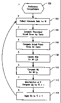
Figure 1 is a flowchart of an exemplary embodiment of the inventive
traffic control system and method. At Step 100 preliminary computations are
performed. At Step 102, data is collected from vehicles during control time
period
Ti. At Step 104, theoretical travel times for turns are computed. At Step 106,
actual travel times for turns are computed. At Step 108, weights W,, for all
values
of indexes i, j and k are updated. At Step 110, weights W for all values of
indexes i and j are computed. At Step 112, maximization of objective function
F
and computation of all corresponding values of is performed. At Step 114, the
green light timings G. obtained at Step 112 are applied to the next control
period
T;+, and the process is reentered at Step 102.
Figures 2A and 2B provide a detailed flowchart of Step 102 shown
in Figure 1. At Step 1021, location data is received and collected by the cell
phone
operator. At Step 1022, the file containing the location data is transferred
to the
traffic control system. At Step 1023, a Positioning Algorithm for putting cell
phones on road sections is applied to the location data. At Step 1024, the
resulting
data is subjected to a filtering or cleaning process. At Step 1025, cell phone
lists
are created. At Step 1026, a special algorithm is applied to each cell phone
record
CA 02392667 2002-07-05
-22-
to determine if a particular cell phone is in a traveling vehicle. If the cell
phone is
determined not to be located within a traveling vehicle at Step 1026 the
record is
rejected at Step 1027 and the process ends. On the other hand, if the cell
phone is
determined to be located within a traveling vehicle at Step 1026 the record is
stored in a memory system at Step 1028. At Step 1029, the vehicular clusters
representing moving vehicles are created. At Step 1030, the vehicles are put
onto
road sections by the Positioning Algorithm. At Step 1031, the vehicle travel
paths
along the road sections are constructed by interpolation methods. At Step
1032,
the data relating to the vehicle positions, travel routes, etc., needed for
adjusting
io phase timing and other traffic control computations are prepared and stored
in the
database.
Future Embodiments And Additional Applications
As described above with respect to the exemplary embodiment, the
present invention provides a system and method for calculating a large number
of
traffic characteristics and parameters not readily available under other
systems. In
particular, it allows computation or estimation of the following parameters
and
quantities: actual travel times of all road sections within a given
geographical
region; actual travel times of all road turns and go-throughs at all
signalized
intersections within a given geographical region; short-term predictions of
those
quantities; and current vehicle loads on all road sections within a given
geographical region.
Based on the above quantities, many important statistical historical
data items may be computed and stored for future use, including the use by
third
parties. Among such data are: vehicle loads at particular roads categorized by
days, hours, etc., vehicle densities at particular roads categorized by days,
hours,
etc., vehicle densities in the vicinities of signalized intersections, average
speeds
along important arteries categorized by days, hours, etc.
Also, numerous additional types of information may be computed
based on the above. These real time or historical data can be readily
transmitted to
other client application programs such as guided navigation systems, traffic
related
and congestion studies, emergency services 911, etc.
CA 02392667 2002-07-05
-23-
Although the invention has been described with reference to
exemplary embodiments, it is not limited thereto. Rather, the appended claims
should be construed to include other variants and embodiments of the invention
which may be made by those skilled in the art without departing from the true
s spirit and scope of the present invention.