Note: Descriptions are shown in the official language in which they were submitted.
CA 02393839 2002-07-16
ELECTROMAGNETIC BRP,F<E AND DRIVE FORCE DISTRIBUTING
APPARATUS FOR VEHICLE USING THE ELECTROMAGNETIC BRAXE
BACKGROUND OF THE INVENTION
Field of the Invention
The present invention relates to an electromagnetic
brake and a drive force distributing apparatus for a
vehicle using the electromagnetic brake.
Description of the Related Art
A differential is located in a power train of a
vehicle to maintain torque distribution between right and
left wheels of the vehicle such that torque is equally
divided between the right and left wheels and to rotate
the outside wheel faster than the inside wheel during
cornering, thereby reliably obtain smooth cornering.
While the primary role of the differential is to obtain
smooth cornering as mentioned above, there is a case that
one of the right and left wheels may be caught to slip in
a muddy place during rough-road running.
In this case, the resistance from the road to the
wheel caught to slip in the muddy place is small, so that
torque is almost transmitted to this slipping wheel and
hardly transmitted to the other wheel. As a result, there
is a problem that the slipping wheel cannot escape from
1
CA 02393839 2002-07-16
the muddy place for lack of the drive force for driving
the wheels. This is a problem in a defect inherent in a
general differential. Known is a special type of
differential having a differential motion limiting
mechanism capable of compensating for the above defect
inherent in a general differential. This type of
differential is referred to as a limited slip
differential (LSD).
A planetary gear type differential is generally
known in the art, for example, such a planetary gear type
differential gear assembly having a limited slip
differential mechanism composed of an electromagnetic
clutch and a multiplate clutch is disclosed in Japanese
Patent Laid-open No. Hei 6-33997. In this differential
gear assembly, an attraction force between a solenoid and
an armature forming the electromagnetic clutch is applied
to the multiplate clutch to press it and selectively
control an engaging force generated in the multiplate
clutch. A connecting member consisting of a plurality of
bars is located between a pressure plate of the
multiplate clutch and the armature. That is, one end of
each bar of the connecting member is fixed to the
pressure plate of the multiplate clutch, and the other
end abuts against an inner circumferential portion of the
2
CA 02393839 2002-07-16
armature when the solenoid is operated.
In the conventional differential gear assembly
mentioned above, the plural bars fixed to the pressure
plate extend in a direction substantially perpendicular
to the pressure plate. Accordingly, in the case that any
of these bars are inclined to the pressure plate, there
is a problem that a pressing force of the armature
attracted by the solenoid to press the pressure plate of
the multiplate clutch may not be uniformly transmitted to
the pressure plate. Further, in the conventional
differential gear assembly described in the above
publication, the electromagnetic clutch controls the
engaging force of the multiplate clutch, so that the
plural bars as pressure members are located so as to
correspond to the inner circumferential portion of the
armature. However, in a multiplate brake structure having
a plurality of brake plates and a plurality of brake
discs, these brake plates and brake discs are generally
located so as to correspond to an outer circumferential
portion of the armature from the viewpoint of the
structure. Accordingly, it is difficult that the
conventional structure described in the above publication
such that the multiplate clutch is operatively connected
to the armature at its inner circumferential portion is
3
CA 02393839 2002-07-16
~
applied to the multiplate brake structure without any
changes.
SUMMARY OF THE INVENTION
It is therefore an object of the present invention
to provide an electromagnetic brake which can achieve
accurate positioning between an armature and a core
member in the radial direction and can accurately control
an engaging force generated in a multiplate brake
mechanism.
It is another object of the present invention to
provide a drive force distributing apparatus for a
vehicle including the above electromagnetic brake which
can arbitrarily distribute a drive force between right
and left drive wheels of the vehicle.
In accordance with an aspect of the present
invention, there is provided an electromagnetic brake
interposed between a fixed housing and a rotating member
at least partially accommodated in said fixed housing.
The electromagnetic brake includes a multiplate brake
mechanism having a plurality of brake plates mounted on
said fixed housing and a plurality of brake discs mounted
on said rotating member so as to be arranged in alternate
relationship with said brake plates; a ringlike core
4
CA 02393839 2002-07-16
member fixed in said fixed housing, said core member
having an annular groove and a first outer diameter; an
annular exciting coil accommodated in said annular groove
of said core member; and a ringlike armature member
arranged in opposed relationship with said annular groove
of said core member, said armature member having a second
outer diameter larger than said first outer diameter. The
electromagnetic brake further includes a cylindrical
pressure member provided so as to surround the outer
circumferential surface of said core member and be
movable in a direction of pressing said multiplate brake
mechanism as being guided by said core member, said
pressure member having a first end fixed to an outer
circumferential portion of said armature member and a
second end engaged with said multiplate brake mechanism.
With this configuration, accurate positioning
between the armature member and the core member in the
radial direction can be achieved by the cylindrical
pressure member. Further, since the cylindrical pressure
member is fixed to the armature member, inclination of
the armature member with respect to the axial direction
can be prevented, and a gap defined between the armature
member and the core member can be accurately uniformed in
the radial direction, thereby allowing accurate control
CA 02393839 2002-07-16
of an engaging force generated in the multiplate brake
mechanism. Accordingly, a braking function can be
achieved without direct metallic contact, and an
attraction force between the core member and the armature
member can be efficiently transmitted to the multiplate
brake mechanism. Further, the rigidity of the components
of the electromagnetic brake in relation to the
transmission of the attraction force is considered to
minimize the elastic deformation of these components,
thereby reducing the hysteresis and stably generating the
attraction force.
Preferably, said core member has a plurality of
fastening portions adapted to be fastened to said fixed
housing, said fastening portions projecting radially
outward from the outer circumference surface of said core
member, and said pressure member has a plurality of
cutouts for allowing insertion of said fastening portions
of said core member. With this configuration, accurate
positioning of the core member in the radial and axial
directions with respect to the fixed housing can be
achieved by the fastening portions. Furthermore, by
forming the cutouts in the cylindrical pressure member,
the pressure member fixed to the armature member can be
fastened to the fixed housing in the condition where the
6
CA 02393839 2002-07-16
pressure member is fitted with the core by inserting the
fastening portions of the core member into the cutouts of
the pressure member. Thus, the assembly of the
electromagnetic brake can be easily performed.
Preferably, said core member has an inner
circumferential portion and an outer circumferential
portion divided from each other by said annular groove,
the sectional area of said inner circumferential portion
being substantially equal to that of said outer
circumferential portion. With this configuration, the
attraction force can be uniformed in the radial direction
of the core member. More preferably, the inner
circumferential surface of said pressure member is formed
with a plurality of projections spaced apart from each
other in the circumferential direction, and said pressure
member is movable in said pressing direction so that said
projections of said pressure member is in sliding contact
with the outer circumferential surface of said core
member. With this configuration, the cylindrical pressure
member can be moved axially straight as being guided by
the core member when the armature member is attracted to
the core member. Accordingly, a pressing force uniform in
the circumferential direction can be applied to the
multiplate brake mechanism.
7
CA 02393839 2002-07-16
Further, the projections for ensuring the accuracy
of alignment of the pressure member are formed on a part
of the inner circumferential surface of the pressure
member rather than the whole thereof, thereby allowing
simplification of the structure and a reduction in
friction during axial movement of the pressure member.
Further, since the pressure member is provided so as to
surround the outer circumferential surface of the core
member, the second end of the pressure member can press
the brake plates and the brake discs of the multiplate
brake mechanism at a substantially central position in
the effective radius. Accordingly, a uniform pressing
force can be applied to the brake plates and the brake
discs of the multiplate brake mechanism.
In accordance with another aspect of the present
invention, there is provided a drive force distributing
apparatus for a vehicle having a pair of drive wheels
which includes a fixed housing; a first axle connected to
one of said drive wheels; a second axle connected to the
other drive wheel; an input shaft rotatably mounted in
said fixed housing and connected to a drive source; a
first planetary gear assembly having a first ring gear
operatively connected to said input shaft, a first
planetary carrier fixed to said first axle, a first sun
8
CA 02393839 2002-07-16
gear rotatably mounted on said first axle, and a first
planet gear carried by said first planetary carrier so as
to mesh with both said first ring gear and said first sun
gear; a second planetary gear assembly having a second
ring gear operatively connected to said input shaft, a
second planetary carrier fixed to said second axle, a
second sun gear rotatably mounted on said second axle,
and a second planet gear carried by said second planetary
carrier so as to mesh with both said second ring gear and
said second sun gear; a first multiplate brake mechanism
interposed between said fixed housing and said first sun
gear; a first electromagnetic brake for controllably
operating said first multiplate brake mechanism; a second
multiplate brake mechanism interposed between said fixed
housing and said second sun gear; and a second
electromagnetic brake for controllably operating said
second multiplate brake mechanism; a drive force from
said input shaft being distributed between said first
axle and said second axle by operating said first
electromagnetic brake and said second electromagnetic
brake.
In accordance with a further aspect of the present
invention, there is provided a drive force distributing
apparatus for a four-wheel drive vehicle having a pair of
9
CA 02393839 2002-07-16
first drive wheels and a pair of second drive wheels,
which includes a fixed housing; a first axle connected to
one of said first drive wheels; a second axle connected
to the other first drive wheel; an input shaft rotatably
mounted in said fixed housing and connected to a drive
source; a first planetary gear assembly having a first
ring gear operatively connected to said input shaft, a
first planetary carrier fixed to said first axle, a first
sun gear rotatably mounted on said first axle, and a
first planet gear carried by said first planetary carrier
so as to mesh with both said first ring gear and said
first sun gear; a second planetary gear assembly having a
second ring gear operatively connected to said input
shaft, a second planetary carrier fixed to said second
axle, a second sun gear rotatably mounted on said second
axle, and a second planet gear carried by said second
planetary carrier so as to mesh with both said second
ring gear and said second sun gear; a first multiplate
brake mechanism interposed between said fixed housing and
said first sun gear; a first electromagnetic brake for
controllably operating said first multiplate brake
mechanism; a second multiplate brake mechanism interposed
between said fixed housing and said second sun gear; and
a second electromagnetic brake for controllably operating
CA 02393839 2002-07-16
said second multiplate brake mechanism; a drive force
from said input shaft being distributed among said first
axle, said second axle, and said second drive wheels by
operating said first electromagnetic brake and said
second electromagnetic brake.
Preferably, said first electromagnetic brake
includes a first ringlike core member fixed in said fixed
housing, said first core member having a first annular
groove and a first outer diameter; a first annular
exciting coil accommodated in said first annular groove
of said first core member; a first ringlike armature
member arranged in opposed relationship with said first
annular groove of said first core member, said first
armature member having a second outer diameter larger
than said first outer diameter; a first annular pressure
plate axially and movably mounted on any one of said
fixed housing and said first axle at one end portion of
said first multiplate brake mechanism adjacent to said
first core member; and a first cylindrical pressure
member provided so as to surround the outer
circumferential surface of said first core member and be
movable in a direction of pressing said first multiplate
brake mechanism as being guided by said first core member,
said first pressure member having a first end fixed to an
11
CA 02393839 2002-07-16
outer circumferential portion of said first armature
member and a second end engaged with said first annular
pressure plate.
Preferably, said second electromagnetic brake
includes a second ringlike core member fixed in said
fixed housing, said second core member having a second
annular groove and a third outer diameter; a second
annular exciting coil accommodated in said second annular
groove of said second core member; a second ringlike
armature member arranged in opposed relationship with
said second annular groove of said second core member,
said second armature member having a fourth outer
diameter larger than said third outer diameter; a second
annular pressure plate axially and movably mounted on any
one of said fixed housing and said second axle at one end
portion of said second multiplate brake mechanism
adjacent to said second core member; and a second
cylindrical pressure member provided so as to surround
the outer circumferential surface of said second core
member and be movable in a direction of pressing said
second multiplate brake mechanism as being guided by said
second core member, said second pressure member having a
third end fixed to an outer circumferential portion of
said second armature member and a fourth end engaged with
12
CA 02393839 2002-07-16
said second annular pressure plate.
The above and other objects, features and
advantages of the present invention and the manner of
realizing them will become more apparent, and the
invention itself will best be understood from a study of
the following description and appended claims with
reference to the attached drawings showing some preferred
embodiments of the invention.
BRIEF DESCRIPTION OF THE DRAWINGS
FIG. 1 is a schematic plan view showing the
configuration of a FF (front-engine front-drive) vehicle
on which the drive force distributing apparatus according
to the present invention is mounted;
FIG. 2 is a schematic plan view showing the
configuration of a four-wheel drive vehicle on which the
drive force distributing apparatus according to the
present invention is mounted;
FIG. 3 is a sectional view of the drive force
distributing apparatus shown in FIG. 2;
FIG. 4 is an elevational view of a side housing;
FIG. 5 is a right side view of the left side
housing shown in FIG. 4;
FIG. 6A is an elevational view of an annular
13
CA 02393839 2002-07-16
pressure plate;
FIG. 6B is a cross section taken along the line 6B-
6B in FIG. 6A;
FIG. 7A is an elevational view of a ringlike core
member;
FIG. 7B is a cross section taken along the line 7B-
7B in FIG. 7A;
FIG. 8 is a sectional view of a ringlike armature
member;
FIG. 9A is an elevational view of a cylindrical
pressure member;
FIG. 9B is a cross section taken along the line 9B-
9B in FIG. 9A; and
FIG. 9C is an enlarged view of an encircled portion
125 shown in FIG. 9A.
DESCRIPTION OF THE PREFERRED EMBODIMENTS
A preferred embodiment of the present invention
will now be described in detail with reference to the
drawings. FIG. 1 is a schematic plan view showing the
configuration of a front-engine front-drive (FF) vehicle
to which a drive force distributing apparatus 6 having
the electromagnetic brake of the present invention is
applied. A drive force from an engine 2 is transmitted
14
CA 02393839 2002-07-16
through a transmission 4 to the drive force distributing
apparatus 6. The drive force transmitted is distributed
between a left front axle 8 and a right front axle 10 by
the drive force distributing apparatus 6. The drive force
thus distributed drives a left front wheel 12 mounted on
the left front axle 8 and a right front wheel 14 mounted
on the right front axle 10.
FIG. 2 is a schematic plan view showing the
configuration of a four-wheel drive vehicle to which a
drive force distributing apparatus 20 having the
electromagnetic brake of the present invention is applied.
A drive force from an engine 2 drives left and right
front wheels 12 and 14 through a transmission 4 and left
and right front axles 8 and 10. The drive force is also
transmitted through a propeller shaft 18 to the drive
force distributing apparatus 20 having substantially the
same configuration as that of the drive force
distributing apparatus 6 shown in FIG. 1. The drive force
transmitted to the drive force distributing apparatus 20
is distributed between a left rear axle 22 and a right
rear axle 24 at a given ratio. The drive force thus
distributed drives a left rear wheel 26 mounted on the
left rear axle 22 and a right rear wheel 28 mounted on
the right rear axle 24. As will be hereinafter described
CA 02393839 2002-07-16
in detail, the drive force distributing apparatus 20
incorporates a pair of electromagnetic brakes. By
controlling braking forces of the electromagnetic brakes,
the drive force from the propeller shaft 18 can be
arbitrarily distributed between the rear wheels 26 and 28.
Further, in the case of idling the rear wheels 26 and 28,
the drive force from the engine 2 can be entirely
supplied to the front wheels 12 and 14. In this case,
this four-wheel drive vehicle operates as an FF vehicle.
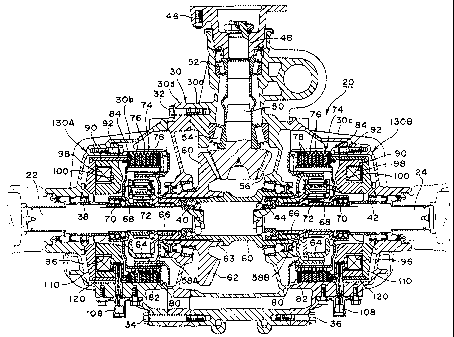
Referring to FIG. 3, there is shown a sectional
view of the drive force distributing apparatus 20.
Reference numeral 30 denotes a fixed housing. The fixed
housing 30 is composed of a central housing 30a, a left
side housing 30b, a right side housing 30c, and an
intermediate housing 30d. The left side housing 30b and
the intermediate housing 30d are fastened to the central
housing 30a by screws 32 and 34. The right side housing
30c is fastened to the central housing 30a by screws 36.
FIG. 4 is an elevational view of the left side housing
30b, and FIG. 5 is a right side view of FIG. 4.
The left rear axle 22 is rotatably supported in the
housing 30 by a pair of bearings 38 and 40. Similarly,
the right rear axle 24 is rotatably supported in the
housing 30 by a pair of bearings 42 and 44. The left rear
16
CA 02393839 2002-07-16
axle 22 is connected to the left rear wheel 26, and the
right rear axle 24 is connected to the right rear wheel
28. Reference numeral 46 denotes a companion flange,
which is fastened to the propeller shaft 18 shown in FIG.
2 by screws (not shown) . An input shaft 50 is rotatably
supported in the housing 30 by a pair of needle bearings
52 and 54. The input shaft 50 is connected at its front
end to the companion flange 46 by splines 48. The input
shaft 50 is formed at its rear end with a bevel gear 56.
A planetary gear assembly 58A is interposed between
the input shaft 50 and the left rear axle 22, and a
planetary gear assembly 58B is interposed between the
input shaft 50 and the right rear axle 24. The planetary
gear assembly 58A has substantially same structure as
that of the planetary gear assembly 58B, so like parts
are denoted by the same reference numerals and only the
planetary gear assembly 58A will now be primarily
described.
Reference numeral 60 denotes an input ring gear of
the planetary gear assembly 58A. The input ring gear 60
is formed at its right end with a bevel gear 62. The
bevel gear 62 of the input ring gear 60 meshes with the
bevel gear 56 of the input shaft 50. The planetary gear
assembly 58B has a ring gear 60' connected to the ring
17
CA 02393839 2002-07-16
gear 60 of the planetary gear assembly 58A by splines 63.
Accordingly, the ring gear 60' of the planetary gear
assembly 58B is rotationally driven by the input shaft 50
through the ring gear 60 of the planetary gear assembly
58A.
The planetary gear assembly 58A further includes a
planetary carrier 64, a sun gear 68, and a plurality of
planet gears 72 (only one of which being shown). The
planetary carrier 64 is fixed to the left rear axle 22 by
splines 66. The sun gear 68 is rotatably mounted on the
left rear axle 22 by a bearing 70. Each planet gear 72 is
carried by the planetary carrier 64 and meshes with both
the sun gear 68 and the ring gear 60. Reference numeral
74 denotes a wet type multiplate brake mechanism. The wet
type multiplate brake mechanism 74 includes a plurality
of brake plates 76 mounted on the housing 30 and a
plurality of brake discs 78 mounted on the sun gear 68.
The brake plates 76 and the brake discs 78 are
alternately arranged.
Each brake plate 76 is mounted on the housing 30 so
as to be axially movable and unrotatable, and each brake
disc 78 is mounted on the sun gear 68 so as to be axially
movable and unrotatable. A snap ring 80 is mounted on the
housing 30 to axially position one end (the right end) of
18
CA 02393839 2002-07-16
the multiplate brake mechanism 74. Fine adjustment of
this positioning is made by controlling the thickness of
a shim 82 located axially adjacent to the snap ring 80.
An annular pressure plate 84 is provided at the
other end (the left end) of the multiplate brake
mechanism 74. As shown in FIG. 6A, the annular pressure
plate 84 has a plurality of projections 86 spaced apart
from each other in the circumferential direction. These
projections 86 are inserted in axial grooves formed on
the inner wall of the housing 30, so that the annular
pressure plate 84 is mounted on the housing 30 so as to
be axially movable and unrotatable. As best shown in FIG.
6B, the annular pressure plate 84 is formed at its outer
circumferential portion with an annular groove 88 for
insertion of a cylindrical pressure member to be
hereinafter described. The annular pressure plate 84 may
be mounted on the sun gear 68.
Reference numeral 90 denotes a ringlike core member,
which has a first outer diameter and an annular groove 96
having a rectangular cross section. As shown in FIG. 7A,
the ringlike core member 90 has a central hole 91 and a
pair of fastening portions 94. Each fastening portion 94
is formed with a hole 95 for insertion of a screw 92 (see
FIG. 3) . As best shown in FIG. 7B, an exciting coil 98 is
19
CA 02393839 2002-07-16
accommodated in the annular groove 96. The core member 90
is divided into an inner circumferential portion 90a and
an outer circumferential portion 90b by the annular
groove 96. The sectional area of the inner
circumferential portion 90a is substantially equal to
that of the outer circumferential portion 90b.
As shown in FIG. 7A, the core member 90 has four
projections 102, a recess 104 for insertion of an
exciting coil terminal 108 (see FIG. 3), and a recess 106
for insertion of a search coil terminal (not shown). As
shown in FIG. 3, a search coil 100 is mounted in the
annular groove 96 adjacent to the exciting coil 98. The
search coil 100 is provided to detect the intensity of
magnetic flux in passing a current through the exciting
coil 98 and control a coil current supplied to the
exciting coil 98 according to the detected intensity of
magnetic flux.
As shown in FIG. 5, the left side housing 30b has a
central hole 39 and a pair of mounting portions 114. Each
mounting portion 114 is formed with a tapped hole 115.
The left side housing 30b further has an annular abutting
portion 116. The core member 90 is fixed to the left side
housing 30b by making the projections 102 of the core
member 90 abut against the annular abutting portion 116
CA 02393839 2002-07-16
of the left side housing 30b, making the fastening
portions 94 of the core member 90 abut against the
mounting portions 114 of the left side housing 30b, and
inserting the screws 92 through the holes 95 of the
fastening portions 94 to threadedly engage the screws 92
into the tapped holes 115 of the mounting portions 114.
A ringlike armature member 110 formed of a magnetic
material is located so as to be opposed to the annular
groove 96 of the core member 90. As shown in FIG. 8, the
armature member 110 has a second outer diameter larger
than the first outer diameter of the core member 90, a
central hole 111, and an annular mounting groove 112
formed at an outer circumferential portion. The armature
member 110 is tapered from its inner circumference toward
its outer circumference as viewed in cross section, so as
to uniform a magnetic path in passing a current through
the exciting coil 98 and to reduce the weight.
A cylindrical pressure member 120 has a first end
(left end) press-fitted with the annular mounting groove
112 of the armature member 110, and a second end (right
end) inserted in the annular groove 88 of the annular
pressure plate 84. In inserting the second end of the
cylindrical pressure member 120 into the annular groove
88 of the annular pressure plate 84, the outer
21
CA 02393839 2002-07-16
circumference of the cylindrical pressure member 120 is
positioned with respect to the annular groove 88. That is,
the second end of the cylindrical pressure member 120 is
inserted into the annular groove 88 of the annular
pressure plate 84 in the condition where the inner
circumference of the cylindrical pressure member 120 is
loosely fitted with the inner circumference of the
annular groove 88 and the outer circumference of the
cylindrical pressure member 120 is closely fitted with
the outer circumference of the annular groove 88.
As shown in FIGS. 9A and 9B, the cylindrical
pressure member 120 has a pair of cutouts 122 for
insertion of the pair of fastening portions 94 of the
core member 90 and four cutouts 124 for insertion of the
four projections 102 of the core member 90. The inner
circumferential surface of the cylindrical pressure
member 120 is formed with six projections 126 spaced
apart from each other in the circumferential direction.
Accordingly, the cylindrical pressure member 120 is
movable in its pressing direction (axial direction) in
the condition where the projections 126 are in sliding
contact with the outer circumferential surface of the
core member 90.
An electromagnetic brake 130A including the
22
CA 02393839 2002-07-16
multiplate brake mechanism 74 is assembled by first
press-fitting the first end (left end) of the cylindrical
pressure member 120 into the annular mounting groove 112
of the armature member 110, next covering the ringlike
core member 90 with the cylindrical pressure member 120
fixed to the armature member 110, next inserting the
second end (right end) of the cylindrical pressure member
120 into the annular groove 88 of the annular pressure
plate 84, and finally fastening the ringlike core member
90 at the pair of fastening portions 94 to the housing 30.
As mentioned above, the sectional area of the inner
circumferential portion 90a of the core member 90 is
substantially equal to that of the outer circumferential
portion 90b of the core member 90. To this end, the width
of the inner circumferential portion 90a is set larger
than that of the outer circumferential portion 90b as
viewed in the cross section perpendicular to the axial
direction. Furthermore, the ringlike armature member 110
is tapered from the inner circumference toward the outer
circumference, so as to uniform a magnetic path in
passing a current through the exciting coil 98. With this
configuration, the armature member 110 can be attracted
by a uniform force over the radius thereof in passing a
current through the exciting coil 98. That is, by
23
CA 02393839 2002-07-16
uniforming the magnetic path, the armature member 110 can
be prevented from being inclined with respect to the
axial direction, and an engaging force of the multiplate
brake mechanism 74 in the electromagnetic brake 130A can
therefore be accurately controlled.
When a current is passed through the exciting coil
98, a predetermined gap is defined between the core
member 90 and the armature member 110, thereby preventing
metallic contact between the core member 90 and the
armature member 110. The axial positioning of the
armature member 110 in the condition where the armature
member 110 is attracted to the core member 90 by passing
a current through the exciting coil 98 is determined by
the mounting portions 114 of the left side housing 30b
for fastening the core member 90 to the left side housing
30b and by the position of the snap ring 80 provided at
the right end of the multiplate brake mechanism 74 and
fixed to the left side housing 30b.
The fine adjustment of this axial positioning is
made by controlling the thickness of the shim 82 located
adjacent to the snap ring 80 to thereby control the
accuracy of the gap between the core member 90 and the
armature member 110. While the left planetary gear
assembly 58A and the left electromagnetic brake 130A have
24
------ ------
CA 02393839 2002-07-16
been described, the right planetary gear assembly 58B and
the right electromagnetic brake 130B are substantially
the same in structure as the left planetary gear assembly
58A and the left electromagnetic brake 130A, respectively,
so the description of the right planetary gear assembly
58B and the right electromagnetic brake 130B will be
omitted herein.
According to the electromagnetic brake 130A in this
preferred embodiment, the cylindrical pressure member 120
is located around the outer circumferential surface of
the ringlike core member 90, so that the right end of the
pressure member 120 can press the plural brake plates 76
and the plural brake discs 78 forming the multiplate
brake mechanism 74 at their substantially central
portions in respect of the effective radius of each
element. Accordingly, a uniform pressing force to the
multiplate brake mechanism 74 can be obtained with no
radial deviation. Further, since the pressing force of
the cylindrical pressure member 120 to the multiplate
brake mechanism 74 is applied axially straight as being
guided by the core member 90, a reduction in control
accuracy of braking engagement due to deflection of the
cylindrical pressure member 120 can be suppressed.
A brake plate with a facing known in the art can be
CA 02393839 2002-07-16
used without any changes as each brake plate 76 of the
multiplate brake mechanism 74, thereby preventing seizure
and judder occurring between metallic plates forming the
multiplate brake mechanism 76 during the operation of the
electromagnetic brake 130A. Since an air gap is defined
between the exciting coil 98 and the armature member 110,
no residual magnetism is generated in a magnetic path in
attracting the armature member 110, thereby improving the
stability of control of an attraction force to the
armature member 110 and eliminating the need for any
parts for canceling an attraction force due to residual
magnetism. Furthermore, it is possible to improve the
falling response in turning off an electrical signal to
the electromagnetic brake 130A and the rising response in
turning on an electrical signal to the electromagnetic
brake 130A. Furthermore, since the electromagnetic brake
130A is simple in structure, the hysteresis can be
reduced.
The operation of this preferred embodiment will now
be described. When both the electromagnetic brakes 130A
and 130B are in an off state with no currents being
passed through the exciting coils 98 of the
electromagnetic brakes 130A and 130B, both the multiplate
brake mechanism 74 are in a disengaged state, so that the
26
CA 02393839 2002-07-16
sun gears 68 of the planetary gear assemblies 58A and 58B
idly rotate about the left and right rear axles 22 and 24,
respectively. Accordingly, the drive force (torque) from
the input shaft 50 is not transmitted to the rear axles
22 and 24. In this case, the rear wheels 26 and 28 idly
rotate and the drive force is entirely transmitted to the
front wheels 12 and 14, so that the four-wheel drive
vehicle shown in FIG. 3 operates in a two-wheel drive
mode (FF vehicle).
When a predetermined amount of current is passed
through the exciting coils 98 of the electromagnetic
brakes 130A and 130B to completely engage both the
multiplate brake mechanisms 74 through the cylindrical
pressure members 120 of the electromagnetic brakes 130A
and 130B, the sun gears 68 of the planetary gear
assemblies 58A and 58B are fixed to the left and right
rear axles 22 and 24, respectively. Accordingly, the
drive force from the input shaft 50 is equally divided
between the rear axles 22 and 24 and transmitted thereto.
As a result, the four-wheel drive vehicle shown in FIG. 2
operates in a four-wheel drive mode to run straight. In
the case of a front-engine rear-drive (FR) vehicle, the
entirety of the drive force is equally divided between
the rear wheels, and this vehicle runs straight.
27
CA 02393839 2002-07-16
In cornering or escaping from a muddy place, the
amperages of the currents passing through the exciting
coils 98 of the electromagnetic brakes 130A and 30B are
controlled to thereby arbitrarily distribute the drive
force from the input shaft 50 between the rear axles 22
and 24, so that optimum cornering control and/or easy
escape from the muddy place can be realized.
While the drive force distributing apparatus 20
provided in relation to the rear axles 22 and 24 has been
described above with reference to FIGS. 2 to 9C, the
drive force distributing apparatus 6 provided in relation
to the front axles 8 and 10 as shown in FIG. 1 also has
similar operations and effects. Further, while the drive
force distributing apparatus 20 is provided in relation
to the rear axles 22 and 24 of the four-wheel drive
vehicle in this preferred embodiment, the apparatus 20
may be provided in relation to the rear axles of an FR
vehicle. Further, while the electromagnetic brake of the
present invention is applied to the drive force
distributing apparatus 20 in this preferred embodiment,
the present invention is not limited to this preferred
embodiment, but may be applied to any mechanisms or
apparatuses having an electromagnetic brake interposed
between a fixed housing and a rotating member.
28
CA 02393839 2002-07-16
While the preferred embodiments of the present
invention have been described using the specific terms,
such description is for illustrative purposes only, and
it is to be understood that changes and variations may be
made without departing from the spirit or scope of the
following claims.
29