Note: Descriptions are shown in the official language in which they were submitted.
CA 02393866 2002-07-17
1
INTEGRATED BRACKET RATCHET SYSTEM
Field of the invention:
The present invention relates to a ratchet system. More particularly, the
present
invention relates to an integrated bracket ratchet system, said ratchet system
enabling to ease the installation and calibration of counterbalancing
mechanisms
of mini-warehouse doors, commercial rolling steel doors and the like, but
being
able to be used also with any other type of counterbalancing installation
where a
torque must be applied and maintained onto a shaft.
Background of the invention:
It is known in the art that most garage doors currently used are
counterbalanced
by different suitable means. Some doors are counterbalanced by means of a
counterweight and other doors are counterbalanced by means of an energy-
storing device, such as a spring under traction or torsion for example. These
counterbalancing systems are typically used to ease the force required by a
user
or a motorized door system to raise and lower the door. in order to put a
spring
under tension, an installer typically must wind the spring and maintain a
given
torque or tension in the spring by different methods and apparatuses.
Actually,
some systems employ a U-bolt or a special bracket which are tightened and
maintained in place when the spring is under tension. Some other systems use a
gear with arm which act as a ratchet.
It is also known in the art that the shaft around which the door is wrapped
usually
rests on a bearing, generally seated in a plug (or "anchor") which maintains
and
holds the spring. Usually, this bearing must be installed on site and this is
often a
problem for the installer because the spring is under tension. To ease
installation,
the spring may be installed at manufacture but in such cases, the plug (or
anchor)
must be installed under tension and kept as such during transportation.
CA 02393866 2002-07-17
2
It is also known in the art that very often, the counterbalancing mechanisms
of the
aforementioned type of installations will often use unidirectional or "one-
way"
bearings. Similarly to regular bearings, unidirectional bearings comprise an
inner
ring which is slidably rotatable within an outer ring, the outer ring being
concentrically mounted about the inner ring, the inner and outer rings being
slidably movable with respect to another by means of bearings positioned
between both rings. Unidirectional bearings are generally designed so as to
have
an inner portion of the outer ring provided with appropriately shaped grooves
so
that when the inner ring is rotated along one direction, there is a relative
movement between the inner and outer rings, whereas when the inner ring is
rotated along the opposite direction, then the bearings of the bearing are
blocked
by the corresponding grooves of the outer ring, thereby blocking relative
movement between the inner ring and the outer ring. It is also known in the
art
that these unidirectional bearings are quite elaborate and costly to
manufacture,
and also are fairly difficult to install, replace, maintain, adjust and/or
repair on
counterbalancing mechanisms which are under tension. Indeed, this results in
additional assembling steps and components required, which is disadvantageous.
Hence, in light of the aforementioned, there is a need for an improved ratchet
system which, by virtue of its design and components, would be able to
overcome
some of the aforementioned problems.
Summary of the invention:
The object of the present invention is to provide an improved ratchet system,
also
known as a "winding system", which satisfies some of the above-mentioned
needs and which is thus an improvement over the ratchet systems known in the
prior art.
CA 02393866 2002-07-17
3
In accordance with the present invention, the above object is achieved, as
will be
easily understood, with a ratchet system such as the one briefly described
herein
and such as the one exemplified in the accompanying drawings.
According to another aspect of the invention, there is also provided the
counterbalancing mechanism provided with the above-mentioned ratchet system.
According to yet another aspect of the invention, there is also provided the
garage door provided with the above-mentioned counterbalancing mechanism.
The objects, advantages and other features of the present invention will
become
more apparent upon reading of the following non-restrictive description of a
preferred embodiment thereof, given for the purpose of exemplification only
with
reference to the accompanying drawings.
Brief description of the drawins~s:
Figure 1 is an exploded view of some of the components of the ratchet system
according to the preferred embodiment of the invention, the ratchet system
being
shown with a shaft of a counterbalancing mechanism.
Figure 2 is a perspective view of the ratchet system shown in Figure 1, the
ratchet system being shown now in an assembled configuration and cooperating
with a shaft of a counterbalancing mechanism in a locked position.
Figure 3 is a partial front plan view of what is shown in Figure 2.
Figure 4 is a perspective view of the ratchet system shown in Figure 1, the
ratchet system being shown now in an assembled configuration and cooperating
with a shaft of a counterbalancing mechanism in an unlocked position.
Figure 5 is a partial front pran view of what is shown in Figure 4.
CA 02393866 2002-07-17
Detailed descriation of a preferred embodiment of the invention:
In the following description, the same numerical references refer to similar
elements. The embodiments shown in the figures are preferred.
Moreover, although the present invention was primarily designed for use with
winding systems of mini-warehouse doors and commercial rolling steel doors, it
may be used with other types of doors and objects and in other fields, as
apparent to a person skilled in the art. For this reason, expressions such as
"mini", "warehouse", "rolling", etc. used herein should not be taken as to
limit the
scope of the present invention and includes all other kinds of doors or items
with
which the present invention could be used and may be useful.
Moreover, in the context of the present invention, the expressions "winding
system", "ratchet system", and any other equivalent expression known in the
art
will be used interchangeably. Furthermore, the same applies for any other
mutually equivalent expressions, such as "rollers" and "pins", as well as
"blocking" and "ratchet" for example, as also apparent to a person skilled in
the
art.
In addition, although the preferred embodiment of the present invention as
illustrated in the accompanying drawings comprises various components and
although the preferred embodiment of the ratchet system 1 as shown consists of
certain geometrical configurations as explained and illustrated herein, not
all of
these components and geometries are essential to the invention and thus should
not be taken in their restrictive sense, i.e. should not be taken as to limit
the
scope of the present invention. It is to be understood, as also apparent to a
person skilled in the art, that other suitable components and cooperations
thereinbetween, as well as other suitable geometrical configurations may be
used
for the ratchet system 1 and corresponding parts according to the present
CA 02393866 2002-07-17
invention, as briefly explained herein, without departing from the scope of
the
invention.
Broadly described, the present invention relates to a ratchet system 1 for use
with
5 a counterbalancing mechanism of a garage door, as well as to the
counterbalancing mechanism and the garage door associated thereto.
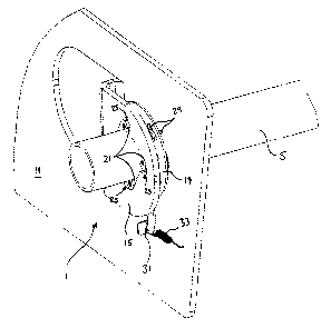
As shown in the accompanying drawings, the ratchet system 1 preferably
comprises support means 3 for supporting a shaft 5 of the counterbalancing
mechanism of the garage door, the shaft 5 being rotatable about the support
means 3. The ratchet system 1 preferably also comprises blocking means 7
operable between locked and unlocked positions. In the locked position, the
blocking means 7 are operatively connected to the shaft 5 and allow it to
rotate
along one direction, while blocking its rotation along the opposite direction.
In the
unlocked position, the blocking means 7 are operatively disconnected from the
shaft 5 and allow it to rotate freely in both directions. Preferably also, the
ratchet
system 1 comprises actuating means 9 for operating the blocking means 7
between the locked and unlocked positions.
Preferably, the support means 3 comprise a bracket 11 having a main body
provided with a first orifice 13 and a flange 15 provided with a second
similar
orifice 17, the first and second orifices 13, 17 being positioned preferably
opposite to one another, as better shown in Figure 1. The bracket 11 is
preferably
mounted to a wall by suitable fasteners, such as bolts and the like, as
apparent to
a person skilled in the art.
Preferably also, the blocking means 7 comprise a guide plate 19 and at least
one
roller 21. According to the particular embodiment of the invention shown in
the
accompanying drawings, the ratchet system 1 preferably comprises a guide plate
19 and four pairs of rollers 21, each pair of rollers 21 preferably consisting
of two
rollers 21 connected to one another by means of a pin 23. Each roller 21 is
preferably devised to cooperate with a corresponding notch 25 of either the
first
CA 02393866 2002-07-17
6
or the second orifice 13, 17, as better shown in Figure 1. The rollers 21 are
preferably maintained in place by the guide plate 19 by introducing the pins
23 of
the pairs of rollers 21 into corresponding holes 27 provided on the guide
plate 19.
Preferably also, the shaft 5 of the counterbalancing mechanism which is
connected to the door by means of a drum is introduced into the corresponding
orifices 13, 17 of the bracket 11 and into the corresponding orifice 30 of the
guide
plate 19. Preferably, the guide plate 19 comprises projections 29 for
maintaining
the plate 19 in place (i.e. aligned) between the flange 15 and the bracket 11,
as
apparent to a person skilled in the art.
Preferably also, the actuating means 9 comprise a handle 31 provided on the
guide plate 19 for actuating the guide plate 19 and corresponding rollers 21
between the locked and unlocked positions, as better shown in Figures 2-3 and
4-5 respectively. Preferably also, a spring 33 having opposite ends connected
to
the guide plate handle 31 and to a point on the bracket 11 respectively is
used for
biasing the guide plate 19 into the locked position.
In its normal use, as better shown in Figure 2, the shaft 5 which is attached
to the
door by means of a drum, on which a rolling steel door is pre-installed for
example, is placed into the orifices 13, 17 of the bracket 11 and the orifice
30 of
the guide plate 19. The bracket 11 is then bolted to the wall. The system 1
can
then be operational. The garage door installer will then turn the shaft 5 with
a pipe
wrench or an appropriate tool and the small rollers 21 will then turn on
themselves freely in their corresponding notches 25. When the installer stops
turning the shaft 5, this shaft 5 is now under tension due to the torque
created by
the torsional spring (not shown) of the counterbalancing mechanism of the
garage door (not shown). As can be easily understood, under this torque, the
shaft 5 wants to turn back to its original position but is then blocked in
position by
the combined effect produced by the rollers 21 and the particular shape of the
orifices 13, 17, i.e. by the friction between the shaft 5 and rollers 21 and
by the
friction between the rollers 21 and the bracket notches 25, in every shaft
position
under tension along this direction. Indeed, the ratchet system 1 according to
the
CA 02393866 2002-07-17
7
present invention, when in the locked position, allows the shaft 5 to turn in
one
direction but blocks it in the other direction, as can be easily understood by
a
person skilled in the art.
The tension thus created by the torsional spring will be maintained with the
ratchet system 1. Furthermore, as also apparent to a person skilled in the
art, a
user of the ratchet system 1 or a garage door installer may also further turn
the
shaft along the first direction to further increase the torque. This
additional torque
created will also be maintained with the ratchet system 1 in the manner
explained
hereinabove. In contrast, the guide plate 19 is designed to allow to disengage
the
rollers 21, as shown in Figure 3, and thus reduce the torque on the shaft 5
accordingly. In its normal use, the guide plate 19 is preferably maintained in
place
(i.e. preferably, the locked position) by the spring 33. Under this position,
the
guide plate 19 forces rollers 21 in one direction. As long as the shaft 5
turns in the
allowable direction, the rollers 21 will turn on themselves, whereas as soon
as the
shaft 5 is released, the tension on the spring forces the rollers 21 against
the
notches 25 of the orifices 13, 17 which in turn blocks the shaft's rotation.
To
decrease the torque on the shaft 5, installer simply has to pull the handle 31
of
the guide plate 19 and disengage the rollers 21, the shaft 5 is then free to
be
unwind with a special tool such a pipe wrench for example. Figures 4 and 5
show
this movement, in which handle 31 is pulled and rollers 21 are forced against
bigger cavity section of the notches 25 where their special shape move rollers
21
away from the shaft 5. This movement of the guide plate 19 lets the shaft 5
free
to turn in both directions.
Several modifications can be made to the above-mentioned ratchet system 1,
without departing from the scope of the present invention. Indeed, the guide
plate
19 and the handle 31 thereof may be placed and designed in a way that gravity
will act to replace the effect of the spring 33. The orifices) 13, 17 may be
integrated in another plate or a single bracket 11 and their shapes may be
devised to block the shaft 5 in both directions. Furthermore, the system 1 may
be
CA 02393866 2002-07-17
connected or joined with ordinary bearings, thus eliminating the need for twQ
guide plates.
As may now be appreciated, the present invention is a substantial improvement
over the prior art in that by virtue of its design and components, the ratchet
system 1 according to the present invention acts as a unidirectional bearing,
without the use of an inner ring. Indeed, as may now be appreciated, the
ratchet
system 1 according to the present invention uses the shaft 5 of the
counterbalancing mechanism as the inner ring. Furthermore, the present
invention is also advantageous in that, by virtue of its design and
components,
fewer components are required for achieving the same result as with a
unidirectional bearing and thus less material is used, thus resulting in
substantial
savings. Moreover, the present invention is also advantageous in that the
ratchet
system 1 may be activated or disactivated by simply operating its handle 31.
In
addition, the present invention is also a substantial improvement over the
prior art
in that, by virtue of its design and components, it may act as an adjustment
device in order to trigger or untrigger the rotation of the shaft 5 with
respect to the
bracket 11 so as to be able to adjust the tension which is loaded onto the
torsional spring. Hence, in view of the above, it may now be appreciated that
the
present invention represents an important advantage over previous devices
known in the prior art, in terms of performance and in terms of costs.
Of course, numerous modifications could be made to the above-described
embodiments without departing from the scope of the invention as apparent to a
person skilled in the art.