Note: Descriptions are shown in the official language in which they were submitted.
CA 02394009 2003-O1-08
IGNITION sp~Rxc pLUG
BACKGROUND 4F THE INVENTION
Field of The Invention
The present invention relates to an improved
ignition spark plug and more particularly to a spark plug
for use in an internal combustion engine which includes a
circular plate-type center electrode which faces an outer
electrode in opposing relationship for providing a spark,
whereby the combustion ignited by the spark plug of a
larger size is completed faster than normal combustion
ignited by a smaller diameter or area of spark.
DESCRIPTION OF REI~1TED ART
Various types of ignition spark plugs are known in
the art. Generally, as shown in FIG, l, a conventional
ignition spark plug includes a main body portion having a
threaded cylinder engaging end 117 with an L-shaped metal
pin or overhanging electrode 111 and a tapering portion
116 extending from the main body portion and a contact or
center electrode 112 disposed at its inner end and spaced
inwardly from the overhanging electrode 111.
However, such a conventional ignition spark plug
suffers from a number of problems. F'or example, since
combustion of the conventional ignition spark is ignited
by a small diameter or area of spark, the combustion is
not fully completed and sufficiently fast, and
accordingly the conventional ignition spark plug cannot
increase engine power in a flame discharging spark.
Also, since such a conventional ignition spark plug
cannot expect complete combustion, the conventional
ignition spark plug cannot improve the starting ability
1
CA 02394009 2005-04-13
of the engine and cannot prevent exhaust gas from fuming
out.
SU1~IARY OF THE INVENTION
Embodiments of the present invention may provide an
improved ignition spark plug which eliminates the above
problems encountered with conventional ignition spark
plugs.
Embodiments of the present invention is may provide
an ignition spark plug which includes an outer electrode
and a circular plate-type center electrode extending from
the center electrode within a center bore for facing an
outer electrode in an opposing relationship for providing
a spark, whereby the combustion ignited by a spark of
larger size is completed faster when compared with that
of a conventional ignition spark plug.
Embodiments of the present invention may to provide
an ignition spark plug which is simple in structure,
inexpensive to manufacture, durable in use, and refined
in appearance.
Further scope of applicability of the present
invention will become apparent from the detailed
description given hereinafter. It should be understood,
however, that the detailed description and specific
examples, while indicating preferred embodiments of the
invention are given by way of illustration only, since
various changes and modifications within the spirit and
scope of the invention will become apparent to those
skilled in the art from this detailed description.
f
Briefly described, the present invention is directed
to an ignition spark plug which includes an outer
electrode and a circular plate-type center electrode
extending a short distance from a center electrode within
a center bore, wherein the circular plate-type center
2
CA 02394009 2005-04-13
electrode has at least one groove and a plurality of
teeth disposed at the periphery of the circular center
electrode for improving the combustion of an engine and
preventing exhaust gas from fuming out.
According to an aspect of the present invention,
there is provided an ignition spark plug which comprises
an insulator containing a center bore, a center electrode
extending through the center bore in the insulator; a
circular plate-type center electrode attached to and
extending from one end of said center electrode, said
circular plate-type center electrode including: a
plurality of grooves provided at the periphery of the
circular plate-type center electrode defining a tooth
wheel for expanding the size of the spark in an ignition
chamber; and a ring electrode disposed at an end of a
threaded metal shell extending from a metal housing and
spaced apart from said circular plate-type center
electrode for forming a spark gap or an arc, whereby the
improved ignition spark plug provides an excellent
starting ability of the engine, completes the combustion
of the fuel in the ignition chamber, and prevents the
exhaust gas from fuming out.
BRIEF DESCRIPTION OF THE DRAWINGS
The present invention will become more fully
understood from the detailed description given
hereinbelow and the accompanying drawings which are given
by way of illustration only, and thus are not limitative
of the present invention, and wherein:
FIG. 1 is a perspective view of a conventional
electrode of an ignition spark plug;
FIG. 2 is a partially sectioned side view of one
possible embodiment of an ignition spark plug according
to the present invention;
3
CA 02394009 2005-04-13
FIG. 3 is a perspective view of a circular plate-
type center electrode of the ignition spark plug of
FIG. 2;
FIG. 4 is a top plan view of a circular plate-type
center electrode of the ignition park plug of FIG. 2;
FIG. 5 is a top plan view of a second embodiment of
the circular plate-type center electrode of the ignition
spark plug according to the present invention;
FIG. 6 is a sectional side view of the circular
plate-type center electrode of FIG. 5;
FIG. 7 is a top plan view of a third embodiment of
the circular plate-type center electrode of the ignition
spark plug according to the present invention; and
FIG. 8 is a top plan view of a fourth embodiment of
the circular plate-type center electrode of the ignition
spark plug according to the present invention.
3a
CA 02394009 2005-04-13
DETAILED DESCRIPTION OF THE PREFERRED EMBODIMENTS
Referring now in detail to the drawings for the
' purpose of illustrating preferred embodiments of the
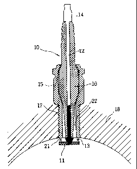
present invention, the ignition spark plug 10 for use in
an internal combustion engine as shown in FIGS. 2, 3 and
4 includes a center electrode 14 extending through a
center bore 12 in an insulator 16 mounted in a central
passage 22 through a threaded metal shell 17, and a
circular plate-type electrode 11 crossly attached to the
center electrode 14 within the center bore 12. The
threaded metal shell 17 extends from a metal housing 15
and has a ring electrode or outer electrode 21 disposed
at an end portion thereof.
As shown in FIG. 2, the ring electrode 21, which
extends from the threaded metal shell 17 is spaced from
the circular plate-type center electrode 11 for forming a
spark gap or an arc 13. Thus, the surface of the
circular plate-type center electrode 11 becomes the
spark-discharging portion and the surface of the ring
electrode 21 becomes the spark-landing portion. The
surfaces of the spark-discharging and spark-landing
portions are disposed in opposing relation with respect
to each other.
Referring to FIGS. 3 and 4, the circular plate-type
center electrode 11 has an aperture for firmly receiving
one end of the center electrode 14 (see FIG. 2) within
the center bore 12 and a plurality of grooves 19 which
define teeth 24 disposed at the periphery of the circular
plate to produce a toothed wheel. The discharging
surface of the circulate plate-type center electrode 11
is surrounded by the landing surface of the ring
electrode 21. Therefore, fuel on the opposite side of
the ring electrode 21 is ignited substantially
simultaneously with the ignition of
4
CA 02394009 2003-O1-08
fuel by the spark between the ring electrode 21 and the
center electrode 11.
The plurality of teeth 24 define a plurality of
spark-discharging ports in the form of a closed and
shaped geometric figure for accelerating a spark between
the center electrode 11 and ring electrode 21. When the
geometric figures are in the form of teeth 24, the spark-
discharging portion and the spark-landing portion are
annular, so that combustion in an ignition chamber 18 is
completed for improving the starting ability of an engine
and preventing exhaust gas Pram fuming out.
Referring in detail to FIGS. 5 and 6, there are
illustrated a second embodiment of the circular plate-
type center electrode 11 which includes a plurality of
openings 20 and a plurality of grooves 19 and teeth 2.4
for expanding the spark-discharging port so as to
accelerate the spark in the ignition chamber 18.
As shown in FIG. 7, there is illustrated a third
embodiment of the circular plate-type center electrode
11 " which includes a plurality of V-shaped grooves 1.9'
and a plurality of teeth 24 for expanding the spark-
discharging port so as to accelerate the spark in the
ignition chamber 18. In this case, the plurality of
openings 20 can be disposed ors the circular plate-type
center electrode 11 " .
Referring in detail to FIG. 8, there is illustrated
a fourth embodiment of the circular plate-type center
electrode 11 " ' which comprises a plurality of grooves
19" having a U-shaped outer portion which terminates
into a V-shaped inner portion, said slots being defined
by a plurality of teeth for expanding the spark-
discharging port which accelerates the spark in the
ignition chamber 18. In this case, the plurality of
CA 02394009 2003-O1-08
openings 20 are disposed on the circular plate-type
center electrode 11 " '.
In the illustrated structure, the insulator 16 is
sealed within the metal housing 15 in a conventional
manner. The center electrode 14 has an upper end portion
which is adapted to receive a suitable plug wire (not
shown) in any conventional manner.
As shown in FIGS. 2 and 3, the ignition spark plug
for use in an internal combustion engine according to
the present invention operates as follows. As described
in detail hereinafter, the ring electrode or outer
electrode 21 closely faces the circular plate-type center
electrode 11. The center electrode is attached to the
center electrode 14 disposed within the center bore J.2
and the circular, plate-type center electrode 11 is
provided with the plurality of shaped grooves, for
example, U-shaped, V-shaped or combined U-shaped-V-shaped
grooves. Fuel disposed on the opposite side of the ring
electrode 21 can be effectively ignited simultaneously
with the ignition of fuel by the spark presented between
the circular plate center electrode 11 and the ring
electrode 21.
Accordingly, the ignition spark plug according to
the present invention provides the forming of a spark
with a substantially increased surface area, whereby the
commencing of combustion is more effective than
combustion ignited by conventional ignition spark plugs
as shown in FIG. 1. Therefore, the combustion is
completed faster than when using conventional ignition
spark plugs.
Also, the ignition spark plug according to the
present invention provides forming the circular plate-
type center electrode 11 having a plurality of grooves 19,
19' and 19" and teeth 24, which cooperate with ring
6
CA 02394009 2003-O1-08
electrode 21 which extends from the threaded metal shell
17 to scatter the ignited fuel within the ignition
chamber 18, so that the ignition of the fuel is effected
between both of the electrodes 11 and 16.
The ignition spark plug according too the present
invention achieves an excellent starting ability for an
engine by increasing the size of the spark due to
substantial reduction of the burning or combustion time
of the fuel, while requiring no increase in the
electrical power employed to create the spark since the
initial combustion is very smooth in operation, the
timing of respective power strokes, and the actual power
effected by combustion.
The 'invention being thus described, it will be
obvious that the same may be varied in many ways. Such
variations are not to be regarded as a departure from the
spirit and scope of the invention, and all such
modifications as would be obvious to one skilled in the
art are intended to be included in the scope of the
following claims.
7