Note: Descriptions are shown in the official language in which they were submitted.
CA 02394189 2002-06-12
WO 01/44841 PCT/US00/32604
INFRARED BROADBAND DICHROIC GLASS POLARIZER
TECHNICAL FIELD
This invention relates to infrared broadband contrast ratio dichroic glass
polarizers.
BACKGROUND ART
Fabrication of the dichroic glass polarizer is known to the art. One of the
key
processes is heating the elongated metal-halide particles precipitated glass
in a reducing
atmosphere. The reduction rate varies as the square root of the pressure.
Also, the
reduction proceeds with a dependence on the square root of time.
One of the important features of a polarizing body is the bandwidth over which
'
the body is effective. This property takes into consideration not only the
degree of
contrast ratio, but the portion of the spectrum within which the contrast is
sufficiently
high to be useful. A contrast ratio of 40dB has been taken as a point of
reference for
comparison purposes. The lower the reference contrast ratio, the broader the
corresponding bandwidth. I have chosen 40dB contrast ratio because it
represents a
common high performance value specified for polarizer applications.
The peak contrast ratio wavelength for dichroic glass polarizers is determined
by the aspect ratio of the elongated particle. The aspect ratio increases with
the degree
of stress applied to stretch the glass, and thereby the crystals. The
wavelength at which
peak contrast ratio occurs increases with the aspect ratio. The precipitated
halide
particles developed by heat treatment in air atmosphere have a certain size
distribution
in glass matrix. The aspect ratio of subsequently elongated particles,
therefore, has a
CA 02394189 2002-06-12
WO 01/44841 PCT/US00/32604
2
certain distribution. Thus, the chemically reduced metallic particles have a
certain
distribution of the aspect ratios. The application wavelength, which is
bandwidth, is
determined by the combination of the distribution of the peak contrast ratio
wavelength
by one metallic particle and aspect ratio distribution of metallic particles.
Thus, the
bandwidth is determined by the summation of the aspect ratios of the metallic
particle
shapes. The shape of a contrast ratio versus wavelength curve for a polarizing
glass is
therefore the superposition of the peaks for all the particles. The so-called
Center
Wavelength (CW) is the application wavelength range in which peak contrast
ratio
wavelength is optimized with stretching stress and size distribution of silver
halide
particles. For example, the elongation stress and particles size for a
polarizer effective
at 1,500 nm are quite different from one effective at 600 nm. In order to
broaden the
bandwidth, distribution of aspect ratio needs to be broadened. Most
applications in the
near infra-red (NIR) require an applicable wavelength range of 1,300-1,500 nm.
However, other application requires contrast ratio peaks outside this range.
For
example, peaks as low as 980 nm are used for pump laser application in
amplification.
Heretofore, it has been necessary to produce polarizing glass articles on an
individual basis. Thus, it was necessary to design a separate set of
processing
conditions tailored to provide the peak contrast ratio for each application
wavelength.
Then care had to be taken to control the process quite rigidly.
The maximum bandwidth available heretofore with a commercially practical
figure was no more than 200 nm. Broader bandwidth from visible to NIR
wavelengths
region for dichroic glass polarizers are found in U.S. Patent No. 4,908,054.
In the
patent, a contrast ratio greater than 40dB, is obtained from 610 nm to a 1,060
nm,
indicating the bandwidth to be approximately 450 nm. This patent teaches that
pressurized hydrogen atmosphere is effective for broadening the waveband.
Japanese
Patent Office, Kokai Patent Application No. HEI 5 [1993]-208444 describes a
contrast
ratio greater than SOdB with the insertion loss less than O.ldB is obtained at
1,310 and
1,550 nm and describing wider bandwidth than 200 nm in NIR wavelength region.
Glass polarizer with broadband contrast ratio is found in a provisional patent
application, Serial No. 60/027,254, filed September 30, 1996, where a heat
treatment
process for generating silver halide particles is changed in order to impart
wider size
distribution of the halide particles. This wider distribution of the halide
particles results
CA 02394189 2002-06-12
WO 01/44841 PCT/US00/32604
3
in wider distribution of elongated halide particle, after the stretching step.
The wider
distribution of the elongated halide particle results in wider distribution of
the metallic
particles, after the reduction process. Even though this patent does not
describe
quantitative results on broadened waveband, contrast ratio greater than 40dB
was
obtained from about 1,080 nm to about 1,520 nm, indicting bandwidth to be
approximately 440 nm. Further, wider bandwidth is found in the provisional
patent
application, Serial No. (P00210), filed December 4, 1996, where bandwidth, at
a
contrast ratio greater than SOdB, is enlarged to 700-900 nm by the reduction
under
extremely high hydrogen pressure, 100 atmospheres, at a temperature below
400°C.
Broadest bandwidth in NIR region in this patent application is 900 nm
bandwidth,
where the contrast ratio greater than SOdB is obtained from 600 nm to 1,500
nm. This
best result is obtained with two steps reduction process for a CW of about
1,480 nm
product, in which the first process is heat treatment in a hydrogen with one
atmosphere
at 420°C for 4 hours and the second process is with 100 atmospheres at
350°C.
1 S Employment of the extremely high hydrogen pressure would not be a
practical process.
The purpose of my invention is to broaden the application bandwidth of
dichroic glass
polarizer with easy practical process.
DISCLOSURE OF INVENTION
The present invention provides polarized glass articles that have a broadened
high contrast ratio in their applicable wavelength range, including
wavelengths ranging
from 880 nm to 1,690 nm. Practice of the present invention contemplates
employing all
of the steps in the conventional manner, except for the final reduction step.
The present
invention is concerned with the final step in which reduction of the metal
halide to
metal takes place. In a broad sense, it is proposed to carry out the reduction
step at
temperature above at least 405°C for longer duration or at higher
pressure to make a
deeper reduced layer. The process of producing the polarizing glass article
includes the
final step of heating the glass article at a temperature ranging from 400 to
450°C in a
reducing atmosphere by products of time multiplied by pressure greater than
12, where
the units for time and pressure are hour and atmosphere, respectively. More
preferably,
CA 02394189 2002-06-12
WO 01/44841 PCT/US00/32604
4
the temperature ranges from 405 to 4~0°C and the products of time
multiplied by
pressure is greater than 24.
In the present invention, broadening the range is accomplished by expanding
the
band from an original bandwidth to only a shorter wavelength region. Thus, the
employed glass article should be stretched at high stress. In other words, the
CW of the
employed sample should be longer than 1,550 nm. It is desirable that the CW
(or
application wavelength) of the potential products using the present invention
be longer,
since the broadening only took place for shorter wavelength region.
The polarizing glass article comprising a base glass and precipitated silver
particles wherein the polarizing glass article exhibits a contrast ratio of at
least 40 dB
over a wavelength range of 880 nm to 1,690 nm, and, thus a bandwidth of 810
nm. This
means that the contrast ratio is consistent over the entire bandwidth at the
range of
wavelength specified.
The polarizing glass article comprising a base glass and precipitated silver
particles wherein the polarizing glass article exhibits a contrast ratio of at
least 50 dB
over a wavelength range of 980 nm to 1,640 nm, and, thus a bandwidth of 660
nm. This
means that the contrast ratio is consistent over the entire bandwidth at the
range of
wavelength specified.
The significance of the present inventive dichroic glass polarizer for
telecommunication applications is that it replaces commercially available
linear
polarizers, such as birefringent crystal polarizers, other glass polarizers,
and/or
Polarizing Beam Sputters (PBS).
The process of producing the polarizing glass article includes the final step
of
heating the glass article at a temperature ranging from 400 to 450°C in
a reducing
atmosphere for a period of time ranging from 12 to 30 hours. Preferably, the
temperature ranges from 405 to 450°C and the time ranges from 12 to 24
hours. More
preferably, the temperature ranges from 405 to 420°C and the time
ranges from 16 to 24
hours. The bandwidth from 880 to 1.690 nm, where contrast ratio is greater
than 40dB,
is obtained at atmospheric hydrogen pressure for 24 hours at 420°C. We
however can
manipulate both time and pressure. In other words, we can use the reduction
process at
4 atmospheres and 6 hours instead of 1 atmosphere for 24 hours.
CA 02394189 2002-06-12
WO 01/44841 PCT/LJS00/32604
BRIEF DESCRIPTION OF THE DRAWINGS
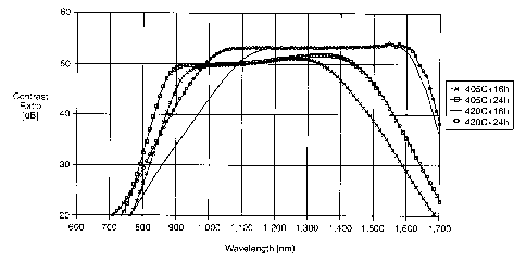
Fig. 1 plots contrast ratio versus wavelength for a commercial dichroic glass
5 article.
Fig. 2 plots contrast ratio versus wavelength for the dichroic glass article
of this
invention.
Fig. 3 plots transmittance versus wavelength for a commercial dichroic glass
article.
Fig. 4 plots transmittance versus wavelength for the dichroic glass article of
this
invention.
BEST MODE OF CARRYING OUT INVENTION
Japanese Patent Application No. 208444 describes a contrast ratio > SOdB at
the
both 1,310 and 1,550 nm wavelengths (bandwidth 240 nm). The present invention
demonstrates that a contrast ratio greater than SOdB was obtained from 980 nm
to 1,640
nm (660 nm bandwidth). Thus, the applicable wavelength range is much wider.
Also,
contrast ratio greater than 40dB was obtained from 880 nm to 1,690 nm,
indicating the
bandwidth to be 810 rmn. As a result, the broadband contrast ratio dichroic
glass
polarizers is in near infrared (NIR) wavelength region. This broadening
application
wavelength is made only with the change in reduction process.
As mentioned earlier, other attempts to broaden bandwidth are known. Those
patents adopt and improve on the known method of producing a polarizing glass
body.
These processes changed early in entire process. Optimization such as
elongation and
hydrogen reduction still would be needed. One process changed the hydrogen
reduction
process. However, this process is not practical because of the employment of
extremely
high hydrogen pressure, up to 100 atmospheres. Facilities for high hydrogen
pressure
are dangerous and generally not available. My process only changes the
hydrogen
reduction process. However. the process does not require high hydrogen
pressure and
is capable of broadening with currently available facilities.
CA 02394189 2002-06-12
WO 01/44841 PCT/US00/32604
6
Copper or copper-cadmium containing photochromic glasses are well known in
the art, having been first described by Armistead et al. in U.S. Patent No.
3,208,860 and
thereafter finding commercial use principally in the manufacture of
photochromic
ophthalmic lenses. Such lenses darken upon exposure to actinic radiation, e.g.
ultraviolet light, and fade in the absence thereof.
Second generation silver halide-containing photochromic glasses exhibiting
improved darkening and fading characteristics have also been recently
introduced. One
family of such glasses has been described by G.B. Hares et al., U.S. Patent
No.
4,190,451.
Photochromic glasses which are preferred for use in the production of surface-
colored photochromic glass articles in accordance with the invention are those
set forth
in the aforementioned Hares et al. Such glasses consist essentially, in weight
percent,
of about 0-2.5% Li20, 0-9% Na20, 0-17% K20, 0-6% Cs20, 8-20%
Li20+Na20+K20+Cs20, 14-23% B203, 5-25% A1203, 0-25% P205, 20-65% Si02,
0.004-0.02% CuO, 0.15-0.3% Ag, 0.1-0.25% Cl, and 0.1-0.2% Br, wherein the
molar
ratio of alkali metal oxides: BOO; ranges between about 0.55-0.85 and the
weight ratio
Ag(Cl+Br) ranges between about 0.65-0.95. As also noted in the Hares et al.
disclosure, such glasses may additionally contain, as optional constituents,
up to about
10% total of other selected oxides or elements for known purposes, including
up to
about 6% Zr02, up to about 3% Ti02, up to about 0.5% PbO, up to about 7% BaO,
up
to about 4% CaO, up to about 3 MgO, up to about 6% Nb205, up to about 4%
La~03,
and up to about 2% F.
Of course, other photochromic glasses have been found suitable for use in the
invention in varying degrees. Such glasses include copper or copper-cadmium
containing glasses set forth in the aforementioned Armistead et al.
Reducing gases which may be used to induce surface coloration in
photochromic glasses according to the invention include any of the reducing
materials
employed for the same or similar purposes in the prior art. Specific examples
are
hydrogen (HZ), forming gas (e.g. 95% NZ+5% H2 by volume), carbon monoxide and
cracked ammonia.
Dichroism of the prior art glass polarizer is due to anisotropy in plasma
resonant
absorption by free electron of the precipitated prolate ellipsoid silver
particles. Fig. 1
CA 02394189 2002-06-12
WO 01/44841 PCT/US00/32604
7
above shows the contrast ratios of the currently available products. In order
to broaden
the application wavelength range, I needed to have large distributions of
aspect ratio
and particle size. It may be possible to enlarge the distribution by changing
the
nucleation heating condition or chemical composition of base glass. My
process,
herein, requires only changes in the current hydrogen firing process in terms
of
temperature, duration and pressure. This is significantly simpler, hence a
more cost
effective and efficient process.
The following examples illustrate this invention.
Example
I conducted four sets of experiments using 0.2 mm thickness standard glass
with
1,550 nm in CW. Conditions were 405 and 420°C and 16 and 24 hours. Two
samples
were used in each condition. The hydrogen was undiluted hydrogen with about
195
sccm flow rate. After the reduction treatment, contrast ratio and
transmittance was
measured with a specially designed spectrophotometer. The measured condition
was
from 600nm to 1,700nm in l Onm sampling step. Fig. 2 shows the contrast ratio
of the
inventive samples.
As can be seen from the figures, the applicable bandwidth of the sample
reduced
at 405°C is located in shorter wavelength region, where there is small
contrast ratio at
the original CW, 1,550 nm. This is because of the partial reduction of silver
particle.
On the other hand, the bandwidth of the sample reduced at 420°C, in
which silver
particle should be completely reduced, still has high contrast ratio at
original CW. In
addition, the applicable wavelength range is extended to only shorter
wavelength
region. Also, longer reduction duration is effective for the broadening. This
phenomenon suggests a slight change in aspect ratio distribution in thickness
direction.
In other words, the aspect ratio of the silver particle interior portion is
smaller than that
at the outer surface portion. Hence, it obtains a large distribution of aspect
ratio
without the partial reduction of silver particle.
The important discovery in the present invention is to reduce the silver
halide
particle layer deeper and deeper at the temperature, where silver halide is
completely
reduced. The reduced layer at the outer surface contributes to a high contrast
ratio at
original CW, in this case 1,50 nm; whereas, the reduced layer in the deeper
portion
CA 02394189 2002-06-12
WO 01/44841 PCT/US00/32604
8
contributes to a high contrast ratio at a shorter wavelength region than the
CW. There
is possibility that the aspect ratio distribution at the outer surface is
equivalent to that at
the interior. Since reduced particles number is larger for deeper reduction,
however, the
number of the reduced smaller aspect ratio particles will be larger, resulting
in possibly
a higher contrast ratio at shorter wavelength (broadening to shorter
wavelength).
Figs. 3 and 4 show transmittance of standard glass products and the inventive
samples used above. Variation in transmittance was less than 0.6% for all
cases. Fig. 4
indicates that transmittance was compatible to that of the standard in Fig. 3.
The results
indicate that no significant difference in transmittance between standard
products and
the inventive samples. Therefore, the inventive process does not degrade
transmittance.
The method broadens the resonant absorption waveband with appropriate
control in reduction condition which are temperature, duration and pressure.
The raw
data for Figs. 2 and 4 appears in Table 1.
CA 02394189 2002-06-12
WO 01/44841 PCT/US00/32604
9
Table
1
Measurement
Results of
the Broadened
Samples
Hydrog en Firing Contrast
Ratio
1.31 ~.m 1.
5_
5
~m
Tem C Time (Hrs.) CR(dBl C
405 16 50.8 33.7
405 16 50.8 34.3
405 24 51.9 41.0
420 16 51.6 41.5
420 16 53.2 53.5
420 16 53.6 54.0
420 24 53.1 53.5
420 24 53.6 54.9
Hydrogen Firing ~, (wavelen
tg-h),
CR >
40 dB
Tem C Time (Hrs.) Start End
405 16 870 1480
405 16 870 1480
405 24 840 1550
420 16 840 1560
420 16 960 1700
420 16 980 1700
420 24 870 1660
420 24 900 1700
As a result, the reduction proceeds with a dependence on the square root of
time
and pressure. Therefore. shorter reduction cycle is applicable, when higher
pressure is
employed. For example. the employed reduction process of 24 hours at
atmospheric
pressure corresponds to 8 hours at 3 atmospheres.
Although the now preferred embodiments of the invention have been set forth,
it
will be apparent to those skilled in the art that various changes and
modifications may
CA 02394189 2002-06-12
WO 01/44841 PCT/US00/32604
be made thereto without departing from the spirit and scope of the invention
as set forth
in the following claims.