Note: Descriptions are shown in the official language in which they were submitted.
, 0
CA 02394411 2008-10-23
METHOD OF PROCESSING A SAMPLE CONTAININg
AT LEAST ONE BIOLOGICAL ELEMENT
10 BACKGROUND
The following relates generally to a structure and a
method for determining an item of interest in a sample. More
specifically, the following relates to determining an item bf
interest that may be or include all or portions of a specific
region of DNA, RNA, fragments, complements, peptides,
polypeptides, enzymes, prions, proteins, messenger RNA,
transfer RNA, mitochondria' RNA or DNA, antibodies, antigens,
allergens, parts of biological entities such as cells, virons
or the like, surface proteins, functional equivalents of the
above, etc.
To provide information about a patient's health, a number
of tests can be performed on a patient sample, such as the
patient's bodily fluids. These bodily fluids may include
1
WO 01/55708 CA 02394411 2002-06-11
PCT/US01/02895
serum, whole blood, urine, swabs, plasma, cerebra-spinal
fluid, lymph fluids, tiosue solids, etc. The tests performed
on the patient's bodily fluids can determine an item of
interest, such as those stated above, in the bodily fluids.
Based on the determination of the item of interest in the
patient's bodily fluids, information about the patient's
health status can be obtained.
SUMMARY
Embodiments described herein provide methods of
processing a sample containing at least one biological
element. One method comprises introducing a first conductor
and a second conductor into the sample. A voltage is applied
between the first conductor and the second conductor. The
voltage is adjusted to reduce an ability of the at least one
biological element to be amplified or detected in a PCR
reaction process.
In another method, at least one biological element in a
sample is removably attached to a binding member. A first
conductor and a second conductor are introduced into the
sample. A voltage is applied between the first conductor and
the second conductor. The voltage is adjusted such that the
at least one biological element is removed from the binding
member.
In an additional method, a first conductor and a second
conductor are introduced into the sample containing at least
one biological element. A voltage is applied between the
first conductor and the second conductor. The voltage is
adjusted to unzip the at least one biological element.
2
W001/55708 CA 02394411 2002-06-11
PCT/US01/02895
In a further method, a first conductor and a second
conductor are located adjacent a sample containing at least
one biological element. A voltage is applied between the
first conductor and the second conductor. The voltage is
adjusted to reduce an ability of the at least one biological
element to be amplified or detected in a PCR reaction process.
In an additional method, at least one biological element
in a sample is removably attached to a binding member. A
first conductor and a second conductor are located adjacent
the sample. A voltage is applied between the first conductor
and the second conductor. The voltage is adjusted such that
the at least one biological element is removed from the
binding member.
In yet a further method, a first conductor and a second
conductor are located adjacent a sample containing at least
one biological element. A voltage is applied between the
first conductor and the second conductor. The voltage is
adjusted to unzip the at least one biological element.
BRIEF DESCRIPTION OF DRAWINGS
Fig. 1 is a perspective view of a structure described
herein;
Fig. 2 is a perspective view of the structure of Fig. 1;
Fig. 3A is a generic top view of another structure
described herein;
Fig. 33 is a perspective view of the structure shown in
Fig. 3A;
Fig. 4 is a perspective view of a sample queue for use
with the structure of Figs. 3A and 33;
3
W001/55708 CA 02394411 2002-06-11
PCT/US01/02895
Figs. 5A through 5F are perspective views of elements for
use with the structure shown in Figs. 3A and 33;
Fig. 6 is a perspective view of a container and a carrier
for use with the structure of Figs. 3A and 3B;
Fig. 7 is a perspective view of a pipette tip loader for
use with the structure shown in Figs. 3A and 3B;
Fig. 8 is a perspective view of another embodiment of a
pipette tip loader for use with the structure shown in Figs.
3A and 3B;
Fig. 9 is a perspective view of a container loader for
use with the structure of Figs. 3A and 33;
Fig. 10 is a perspective view of a container transporter
for use with structure shown in Figs. 3A and 3B;
Fig. 11 is a magnified view of a portion of Fig. 10;
Figs. 12A through 12P are perspective views of various
embodiments of the container shown in Fig. 1;
Fig. 13 illustrates engagement of the container of Fig.
12E with a mixer;
Fig. 14 shows a port provided in operative relationship
with the process path of Figs. 3A and 33;
Fig. 15 is an exploded perspective view of a pipettor for
use with the structure of Figs. 3A and 33;
Fig. 16 illustrates one operation of the pipettor of Fig.
15;
Fig. 17 illustrates another operation of the pipettor of
Fig. 15;
Fig. 18 is an isometric view of a structure substantially
similar to the structure of Figs. 3A and 3B;
Fig. 19 is an isometric view of a structure substantially
similar to the structure of Fig. 18;
4
WO 01/55708 CA 02394411 2002-06-11
PCT/US01/02895
Fig. 20 is a top view of another structure substantially
similar to the structure of Figs. 3A and 38;
Fig. 21 is a top view of an additional structure
substantially similar to the structure of Fig. 20;
Fig. 22 is a top view of a further structure
substantially similar to the structure of Fig. 21;
Fig. 23 is a top view of another structure substantially
similar to the structure of Fig. 22;
Fig. 24 is a top view of yet a further structure
substantially similar to the structure of Fig. 23;
Fig. 25 is a top view of yet a further structure similar
to the structure of Figs. 3A and 38;
Fig. 26 is a top view of yet a further structure similar
to the structure of Figs. 3A and 3B;
Figs. 27A through 27F are perspective views of a
container and seal for use with the structure of Figs. 3A and
3B;
Fig. 28 is a perspective view of an optical configuration
for use with the structures described herein;
Fig. 29 is a generic view of operation of a portion of
the structures described herein;
Fig. 30A is a sectional view of a portion of the
structures described herein;
Fig. 308 is a top view of the portion of Fig. 30A;
Fig. 31 is a sectional view of a portion of the
structures described herein;
Fig. 32A is a sectional view of a portion of the
structures described herein;
Fig. 328 is a top view of the portion of Fig. 32A;
Fig. 33 is a generic plan view of a portion of the
structures described herein; and
5
=
WO 01/55708 CA 02394411 2002-06-11
PCT/US01/02895
Fig. 34 is a schematic diagram of a circuit described
herein.
DETAILED DESCRIPTION OF ILLUSTRATED EMBODIMENTS
The embodiments described herein relate to methods and
structures for determining an item of interest in a sample.
The item of interest may be a specific region or regions of
DNA or RNA, or may be fragments, complements, peptides,
polypeptides, enzymes, prions, proteins, messenger RNA,
transfer RNA, mitochondrial RNA or DNA, antibodies, antigens,
allergens, parts of biological entities such as cells, virons
or the like, surface proteins, functional equivalents of any
of these, concentrations of any of these or any other desired
element of the sample. In an exemplary embodiment, the item
of interest may be selected from, but is not limited to
specific DNA or RNA regions, antibodies, or antigens including
but not limited to, CT, CT/GC, MT, HCV, HBV, HPV, HIV, CMV,
HLA, HTLV, and other items related, but not limited to,
infectious diseases, genetic markers, cancers, cardiovascular
items, pharmacogenetic items, etc. In some embodiments, the
item of interest may be selected from, but not limited to
antibodies to HCV, antibodies to HIV 1/HIV 2, antibodies to
hepatitis B core antigen (HBcAb), carcinoembryonic antigen
(CEA), cancer antigen 19-9 (CA19-9), Hepatitis B Surface
Antigen (HBsAg), antibodies to Hepatitis B Surface antigen
(HBsAb), alpha-fetoprotein (AFP), Total prostate specific
antigen (Total PSA), Free PSA, Thyroid stimulating Hormone
(TSH), luteinizing hormone (LH), follicle stimulating hormone
(FSH), beta human chorionic gonadotropin (B-hCG), Free
6
- ,
= CA 02394411 2008-10-23
Thyroxine (Free T4), Free triiodothyronine (Free T3), Total
T4, Total T3, Progesterone, Testosterone, Estradiol,
Prolactin, vitamin B12 (B12), Folate, Glycated Hemoglobin, and
Ferritin. In essence, almost anything can be the item of
interest.
The structures and methods described herein may be
employed in a number of different configurations. For the
sake of clarity of understanding, the structures and methods
will be discussed with respect to their employment in a
DNA/RNA sample preparation, amplification, and detection
analyzer which performs approximately 100 or more
determinations of items of interest in a sample in an hour, or
if the sample preparation is divided, approximately 300 or
more determinations of items of interest in a sample in an
hour. Alternately, the same structure may be used as an
immunoassay analyzer or as both an immunoassay analyzer and
DNA/RNA analyzer. It is to be noted that the structures and
methods can be used in other employments, such as in analyzers
which perform 600, 400,'200, 50, etc. determinations in an
hour.
A number of structures may be joined together or
integrated to meet individual needs, such as modifying the
number of tests performed in a given time period (throughput),
tailoring the items of interest to be determined, etc. For
example a number X of structures which perform Y
determinations in a given hour may be connected such that the
connected structures perform XY determinations in an hour. If
desired, the resources of the structures may be allocated in a
manner substantially similar to that disclosed in
U.S. Patent No. 6,022,746, filed on March 12, 1998. That
application is assigned to the assignee of the
7
- _
CA 02394411 2008-10-23
present case.
In other embodiments, one or more structures may be
operatively connected with another analyzer, such as an
immunoassay analyzer (e.g. disclosed in U.S. Patent No.
5,795,784 referenced below), a blood analyzer (e.g. disclosed
in U.S. Patent No. 5,891,734 referenced below), and the like.
It is to be noted that all such structures may perform
all similar determinations of items on interest in
substantially the same way. For instance, all determination
process steps for all similar items of interest may be
performed within the same time frame, such as 36 seconds,
irrespective of the number of determinations to be performed
by the given structure. These structures may include common
elements, such as reagents, disposable articles, other
elements, such as fluids and the like, delivery technologies,
determination step performance mechanisms, software, etc.
In other applications, the structure may be joined, e.g.
with a conveyor system and the like, along with supporting
hardware and software, such that the structure can be used
with different structures or analyzers, such as clinical
chemistry or hematology analyzers and the like, in the same
setting. This conveyor system may move samples among the
structures such that different determinations can be made with
respect to one sample. Also, while operation of the structure
is described herein with respect to only one structure, for
the sake of clarity, it is to be remembered that multiple
structures can operate in the same or in different fashion,
either simultaneously or at different times. Furthermore,
steps of one method of operation can be combined with steps of
8
-
CA 02394411 2008-10-23
=
another method of operation to arrive at yet more methods of
operation.
Any of the structures or methods described herein may be
combined, in any suitable fashion, with the structures or
methods or portions thereof described in currently available
literature, such as the following United States Patents. As
all of these patents are assigned to the assignee of the
present case.
The United States
Patents are: 5,468,646, 5,536,049, 5,543,524, 5,545,739,
5,565,570, 5,669,819, 5,682,662, 5,723,795, 5,795,784,
5,783,699, 5,856,194, 5,859,429, 5,891,734, and 5,915,583.
Construction of structures described herein is intended
to analyze specimens for various items of interest in a cost-
effective way. The structures allow a user to supply a sample
to the structure, to have the structure process, e.g.
incubate, prepare, lyse, elute, analyze, read, etc., the
sample and to have the structure report a result of the
process. Structure sub-components include apparatus and
methods of mixing, aspiration and dispense of materials, such
as samples and reagents, incubation, chemistry separation, and
detection, just to name a few. In general terms, structure
construction implementation for chemistry automation may be
driven by many factors such as desired patient sample addition
methods, reagent addition methods, throughput (number of
determinations per given time period), contamination reduction
methods, detection methods, degree of mixing, and incubation
temperature and duration needs.
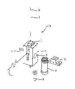
Fig. 1 discloses a structure la amenable to a relatively
decreased throughput, such as about 1 determination per every
1.5 hours, environment. The structure la comprises a first
9
=
_
CA 02394411 2008-10-23
container I. removably placed in a base 2. In some
embodiments, the base 2 may have a construction substantially
similar to constructions of the process path disclosed in
above-referenced U.S. Patent No. 5,795,784, in which case, the
structures illustrated in Figs. 1 and 2 can be disposed at
appropriate locations along the process path. Probe 3 is
=
attached to a suitable prime mover such that the probe 3 can
move in multiple directions, if desired. The probe 3 is
fluidly connected at location 3a to suitable structures which
enable the probe 3 to perform aspiration and dispense
functions. These fluidic functions could be implemented with
use of common pump (e.g. syringe, peristaltic, etc.) and valve
technology, some of which is well understood today. The probe
3 can be moved by one of many means such as a Tecan gantry
(Tecan RSP model series, Tecan Switzerland), an Abbott theta-Z
robot (part number 78479, Abbott Laboratories, Abbott Park
Illinois) or the like. Base 2 could be fabricated out of any
desirable material, such as machined and coated aluminum and
the like. In an exemplary embodiment, the base 2 is made with
6061-T6 aluminum with a MIL-A-63576 Type I finish. The first
container 1 could be fabricated out of any desirable material,
and may be molded out of a polyethlyne (DOW 30460M HDPE or
Chevron79512, for example) or polypropylene (MontelIPD701N,
for example), or polystyrene MOW 666, for example). In the
illustrated embodiment, the first container 1 is sized to
contain an amount, such as about 7 mL, of fluid, such as
sample and reagent. Figs. 12A through 12P show alternative
constructions of the first container 1.
It is to be noted that the construction of the base 2 may
be modified to accommodate or complement various constructions
of the first container 1 as the base 2 provides features to
WO 01/55708 CA 02394411 2002-06-11
PCT/US01/02895
accept first container 1 and to house a retractable magnet 4
shown in Figs. 1 and 2.
Magnet 4 can be moved with respect to the first container
1 at selected times during performance of a given
determination of an item of interest in a sample in the first
container 1. The movement of the magnet 4 can effect
performance of a step in the determination process thereby
allowing that step to be selectively automatically performed
or avoided as desired. In one embodiment, the magnet 4 may be
moved relatively proximate to the container to attract
magnetically responsive particles within the first container 1
to a side wall of first container 1 thereby separating those
particles which may be bound with a desired item of interest
in a patient sample from the remaining patient sample or other
contents of the first container 1.
Before, during or after such magnet 4 induced separation,
probe 3 may aspirate a portion of the first container 1
contents to waste/wash reservoir 10. Subsequent dispense,
separation, and aspiration steps may be employed to enhance
the item of interest determination. During periods of the
determination where magnetic separation is not desired, i.e.
the magnetic separation step is avoided, magnet 4 may be moved
relatively distally with respect to the first container 1 to
reduce effects of the magnetic field of the magnet 4 on the
first container 1 and its contents. If desired, magnetically
responsive particles to which no item of interest is attached
may be attracted to the side wall of the first container 1
while the remaining contents, possible containing an item of
interest, of the first container 1 is removed from first
container 1, such as by the probe 3.
11
W001/55708 CA 02394411 2002-06-11
PCT/US01/02895
In some embodiments, a thermal regulation device (heating
and/or cooling) 7 can be provided with the base 2. The device
7 may be manually or automatically removably connected with
the base 2, may be operated by an appropriate controller, such
as a computer having memory running appropriate routines, and
may utilize currently available thermal transfer means of
conduction, convection, and/or radiation, etc. In one
embodiment, thermally regulated (heated and/or chilled) air is
moved with respect to the first container 1 to thermally
regulate first container 1 contents in a desired manner.
At various times during performance of a given
determination of an item of interest, a sample disposed in
container 8 and reagent contained in container 9 may be added
to first container 1, such as by probe 3. If multiple samples
and/or reagents are desired, an array, such as a conveyor, a
carousel, other movable arrangement, possibly recirculating,
or the like, of multiple containers 8 and/or 9 could be
provided. Containers 8 and 9 could be fabricated out of any
suitable material, such as a polymer like polystyrene (DOW
666), high-density polyethylene (DOW 30460M HDPE or Chevron
9512) respectively, and the like.
To increase preservation of the contents of either
container 8 or 9, a cover 30 (Fig. 5C), substantially similar
to the cover disclosed in U.S. Patent No. 5,795,784 referenced
above, could be added to either container 8 or 9. The cover
may be made from any suitable material, such as Lexington
Medical 3481005 EPDM, Abbott EPDM (Ashland, Ohio) and the
like. Some constructions for containers 8 and 9 and
associated covers can be found in U.S. Patent No's. Des.
30 401,697, Des. 401,699, and Des. 397,938 respectively,
referenced above. A method for fitting a container such as
12
=
CA 02394411 2009-01-20
gt
container 8, to other containers or a carrier is described in
commonly owned U.S. Patent No. 5,915,583.
Once sample and/or reagent is added to first container 1,
probe 3 may be washed, i.e. likelihood of exposure to a
contaminant is reduced, by moving the probe 3 to waste/wash
reservoir 10 for a fluid rinse of the probe 3. In other
embodiments, probe 3 could be modified to incorporate a
disposable tip, such as the pipettor tip disclosed in U.S.
Patent No. 5,232,669 (assigned to the assignee of the present
case).
After intended use of the pipettor tip, the tip
may be ejected from a fluidic/transport interface with the
probe '3 to waste. Another example of a disposable tip 28 is
illustrated in FIG. 5F.
A bore 6 is disposed on the base 2 to accommodate a
detector, such as a photomultiplier tube, a photodiode and the
like. In the illustrated embodiment, the bore 6 is located
opposite magnet 4 in a similar fashion to the like structures
disclosed in U.S. Patent No. 5,795,784. Thus, similar
operations, such as detection of chemiluminescence or other
signal generated by a label, such as a fluorophore and the
like, are possible.
A mixer 5, illustrated in Fig. 2, is also provided on the
base 2. The mixer 5 is coupled to a driver 5a that applies
force to the mixer 5, possibly inducing an orbital motion on
the first container 1 thereby causing mixing of first
container 1 contents at desired times. The base 2 is
constructed to limit first container 1 degrees of freedom
important to the mixing process. Base 2 may include a lid to
assist in controlling degrees of freedom important to the
mixing process. Fig. 13 shows an alternate construction of
13
=.
WO 01/55708 CA 02394411 2002-06-11
PCT/US01/02895
mixer 5. An additional embodiment of a suitable mixer is
disclosed in U.S. Paten: No. 5,795,784.
If desired, the structure la shown in Fig. 1 can be
modified to perform a larger number of determinations, such as
about 100, in a given time period, i.e. a relatively increased
throughput environment. The structure la could be operatively
connected with one or more additional structures la, each of
which possessing one or more of the probe 3, magnet 4, mixer
5, bore 6 for a detector, and the thermal regulation device 7.
In this embodiment, the multiple structures la permit
selective activation of magnet 4, detector 6, heat/cooling
elements 7, mixer 5, sample and reagent aspirations and
dispenses, etc. at desired times during the determination
process, viz, the steps executed by those elements are
selectively automatically performed. With this arrangement, a
determination of an item of interest in a sample can be
conducted over more than one position or with more than one
structure la, thereby allowing at least two samples to be
processed substantially simultaneously.
To streamline operative connection of multiple structures
la, a transport system, such as a conveyor (bounded or
endless), a carousel or the like, could be used to move first
container 1 from one structure la to another. The transport
system may be substantially similar to the process path
disclosed in the above-referenced '784 patent. Depending on
location of the structure(s) la, the transport system and/or
the individual structures can be constructed to provide only
the functions desired to be performed at a given time in a
determination. For example, a relatively large number, such
as 100, structures la could be operatively connected together
14
WO 01/55708 CA 02394411 2002-06-11
PCT/US01/02895
and only a subset, such as 5, of the structures la may include
a mixer 5.
Figs. 3 and 18 show a structure lb essentially comprising
a plurality of structures la located substantially adjacently.
In this embodiment, containers 1 are loaded substantially
automatically onto a first process path 11 from a container
loader and transport 35 illustrated in Fig. 9. Alternately,
first container 1 could be loaded manually or automatically in
a fashion described in the '784 patent. Containers 1 are
moved, possibly one position every selected time interval,
such as every 36 seconds, through the first process path 11 to
various locations along the first process path 11 where
various operations, such as reagent addition, sample addition,
incubation, mixing, washing and the like, are selectively
automatically performed according to requirements of the
intended format or protocol of the determination being
performed. In an exemplary embodiment of the structure lb,
the first container 1 is moved approximately 1.2 inches along
the first process path 11 about every 36 seconds.
The first process path 11 includes at least one
temperature controller or heater to keep the first process
path 11 at a desired temperature. The first process path 11
may be kept at one temperature or any desired number of
temperatures, such as with multiple heaters. In one
embodiment, the heater maintains the first process path 11 at
about 37 degrees Celsius. In another embodiment, one portion
of the first process path 11 may be maintained at about 37
degrees Celsius while another portion of the first process
path may be maintained at about 70 degrees Celsius.
Various methods may be implemented to heat the first
process path 11 to at least one temperature while isolating
WO 01/55708 CA 02394411 2002-06-11
PCT/US01/02895
the container 1 maintained at the least one temperature from
other temperatures. For example, in one embodiment, the first
process path 11 may be used to perform a first incubation,
such as lysis for about 20 minutes at about 37 degrees
Celsius, and a second incubation, such as elution for about 20
minutes at about 50 degrees Celsius, with container 1.
Container 1, being used for both lysis and elution on the
first process path 11, can be thermally isolated from the
second temperature while the container 1 is exposed to the
first temperature, and vice versa.
If the first process path 11 were made of a suitable
material, such as aluminum and the like, and if the first
process path 11 were heated, e.g. conductively, to the first
temperature or the second temperature at an appropriate time,
a member may be introduced to thermally insulate portions of
the first process path 11 exposed to the first temperature
from portions of the first process path 11 exposed to the
second temperature. This member may be an insulating
material, a physical barrier or the like. The member may be
actively cooled or heated based on temperature conditions
measured at the first process path 11 portions specific to the
first temperature, e.g. 37 degrees Celsius, and specific to
the second temperature, e.g. 50 degrees Celsius, thereby
limiting exposure container 1 to the first or second
temperature, as appropriate.
In another embodiment, the first process path 11 is
maintained at a first temperature, for example 37 degrees
Celsius. At a portion of the first process path 11, where it
is desired to maintain a second temperature, for example 50
degrees Celsius, at least one other thermal energy source,
such as an IR source and the like, may be thermally coupled
16
WO 01/55708 CA 02394411 2002-06-11
PCT/US01/02895
with the first process path 11 to provide a desired amount of
heat to the relevant portions of the first process path 11 at
times required. Contents present in container 1 may
experience a thermal rise to the second temperature during
exposure to IR source followed by a thermal degradation to the
first temperature as the container 1 is removed from exposure
to the IR source.
In another embodiment of the structure lb illustrated in
Figs. 10 and 11, once a first container 1 is placed on the
first process path 11, belt 36 moves first container 1 via
engagement with pin 36a on the belt 36. Prime mover 38
engages belt 36 via drive gear 40 and driven gear 41. Prime
mover mount 39 aligns prime mover 38 to driven gear 41 in the
desired fashion.
Returning to Figs. 3A and 3B, samples disposed in
containers 8, such as test tubes and the like, are loaded in
container carriers 27 which are loaded onto input queue 17.
Examples of a sample container 8 and an associated container
carrier 27 are shown in Fig. 6. The container 8 and the
container carrier 27 may be substantially similar to the
container disclosed in above-referenced U.S. Patent No's.
5,915,583 and Des. 401,697.
Input queue 17 may be constructed similarly to a sample
handler like the currently available Abbott FPC Flexible
Pipetting Center or the common structures described in the
784 patent. An example of an input queue 17 is shown in Fig.
4 and comprises a conveyor system like that disclosed in the
784 patent. The embodiment illustrated in Fig. 4 is
constructed such that a structure, such as the structure lb of
Figs. 3A and 3B, may be disposed in space 17a so that the
input queue 17 and the structure lb can cooperate. In this
17
WO 01/55708 CA 02394411 2002-06-11
PCT/US01/02895
embodiment, sample inpu,: and output queues 17 and 17b,
respectively, may be disposed adjacent to each other offset by
a local queue 17c.
A bar code reader 2E is located adjacent the first
process path 11 such that the bar code reader 25 can read a
code associated with the container 8 and/or the container
carrier 27. The bar code reader 25 is used to identify a
given sample located on the input queue 17 at a position
accessible by pipettor 19.
When the bar code reader 25 identifies a sample, pipettor
19 can transfer that sample from container 8 on the input
queue to first container 1 located on the first process path
11. Other items, such as reagents and the like, may be added
to first container 1 by pipettor 19 and pipettor 12 in
accordance with a given determination format. Reagents are
stored in reagent handler 13 which may be similar to the
reagent carousel disclosed in the '784 patent. In an
exemplary embodiment, pipettors 19 and 12 may add reagents to
first container 1 at times specified in the "1 Tube DNA/RNA
20-20 Min Sample Prep Protocol, 1 Tube 1.5 hr PCR End Point
Protocol" specified below.
In addition to pipettor 19 and 12, dispense nozzles (not
shown for clarity) fluidly connected with appropriate pumping
mechanisms may add reagents from bottles 29, 31, and 32 to
first container 1 via fluid dispense nozzles. Containers 29,
31, and 32 are shown in Figs. 5E, 5A, 5B and 19. In one
embodiment, container 31 contains solid phase microparticles,
possibly magnetically responsive, which may require an
agitator to homogenize the container 31 contents, i.e.
resuspend the particles in a fluid medium. The agitator may
be incorporated into a microparticle reagent handler 18 shown
18
W001/55708 CA 02394411 2002-06-11
PCT/US01/02895
in Figs. 3A and 33. This re-suspension could be accomplished
with commonly understood mixing fins, complementary container
fins and/or fin motion among other methods. In a specific
embodiment, resuspension of the particles within container 31
is achieved with a stir bar and associated apparatus also
commonly understood in the field. Some or all containers
described herein may be placed on the structure lb shown in
Figs. 3A and 3B. The contents of the containers may be
preserved with use of reagent seal 30 shown in Fig. 5C and/or
with use of refrigeration. To provide additional flexibility
in dispensing reagents, reagent dispense nozzles operatively
associated with the first process path 11 may be integrated
with transport mechanisms to allow reagents to be dispensed at
any desired position on the first process path 11.
Sometimes, it may be desirable to mix or to agitate the
contents of first container 1. Mixing of first container 1
contents along first process path 11 may be selectively
automatically performed at an selected time by a mixer 5, such
as the mixer 5 shown in Fig. 13. In this embodiment, first
container 1 is operatively engaged via feature 44 which is, in
turn, operatively coupled to gear train 43. Gear train 43 is
configured to induce motion, e.g. orbital, circular or other,
to first container 1 when rotated by prime mover 42. In one
embodiment, mixing occurs at times specified in the "1 Tube
DNA/RNA 20-20 Min Sample Prep Protocol, 1 Tube 1.5 hr PCR End
Point Protocol" specified below.
In an embodiment where pipettors 19 and 12 are configured
for use with disposable pipettor tips 28 shown in Figs. 5F and
19, transport and loading of a tip 28 or a group of tips 28
may be accomplished with loader and transport mechanism 33
19
WO 01/55708 CA 02394411 2002-06-11
PCT/US01/02895
shown in Fig. 7, loader and transport mechanism 34 shown in
Fig. 8 or other equivalent arrangements.
After engagement of a tip 28 by either pipettor 19 or 12,
liquid level sensing (executed by any currently available
method), aspiration from selected container(s), and dispense
to first container 1 occurs. Pipettor 12 or 19 may include an
apparatus which can detect a liquid level and/or temperature.
This apparatus may include, but is not limited to, photo
optics, capacitive members, IR, sonar, or other wave form
generators. After dispense, tip 28 is washed with liquid at
wash station 23 thereby reducing exposure to a contaminant.
Subsequent additions to first container 1 may occur in similar
fashion, as desired. After all desired additions to first
container 1 have been completed, first container 1 contents
may be is aspirated or otherwise removed from first container
1 and dispensed or transferred to desired locations where
other functions, such as genetic sequencing, a pharmacogenetic
test and the like, can be performed. Then, the tip 28 may be
removed from pipettor 12 or 19 and disposed to tip 28 waste
24, thereby reducing exposure to a contaminant. By using a
single tip 28 for multiple reagent and singular sample or
prepared sample manipulations can reduce solid waste and can
provide reduced cost while maintaining desired levels of
contamination reduction. Similar steps may be performed with
the pipettors 12 or 19 even if they do not include a tip 28.
Mixing with mixer 5 or other motions imparted to first
container 1 may induce unintended distribution, e.g.
aerosoling, of fluids contained in first container 1. Fig. 14
shows feature or port 45 integrated into first process path 11
at appropriate locations. Port 45 is fluidly connected with a
fluid pressure source, such as a negative fluid pressure
CA 02394411 2008-10-23
source like a vacuum and the like, that draws air flow above
first container 1 away from adjacent containers 1 on first
process path 11 to a more desirable location. In this method,
undesirable airborne contaminants may be routed to controlled
locations.
Washing of microparticles used in some methods performed
by the structures la and lb, viz. immunodiagnostic and/or PCR
sample preparation methods, may utilize removal, evacuation or
pipetting of unbound or bound microparticles from first
container 1 and/or other constituents of the first container 1
contents, such as if some of the first container 1 contents 48
were attracted to and held by magnet 4.
To perform this washing, at least one wash zone 50 is
located at an appropriate position along first process path
11. Within a wash zone 50 resides a probe 49, shown in Fig.
16, constructed to automatically evacuate or pipette first
container 1 contents, such as unbound or bound microparticles
from first container 1. More than one probe 49, such as 4,
may comprise a single wash zone 50. Washing steps, e.g.
magnetic separation, aspiration, dispense, are further
described in the '784 patent.
Where contamination is a concern, such as with DNA/RNA
determinations, probe 49 can be formed with an outer tube 46
and inner tube 47 as shown in Fig. 15. Outer tube 46 may be
held substantially concentrically with respect to inner probe
47 via member 46a. In some embodiments, the member 46a may
function as a fluid conveying conduit. In one embodiment,
outer tube 46 is fluidly connected to a wash fluid source and
inner tube 47 is fluidly connected to a vacuum source routed
to waste. The wash fluid may be used for many purposes, such
as to chemically wash unbound particles from particles bound
21
W001/55708 CA 02394411 2002-06-11
PCT/US01/02895
to an item of interest held in first container 1, and also to
remove undesirable itemE', i.e. contamination, from inner tube
47 after inner tube 47 comes into contact with fluid, such as
fluid in the first container 1, during evacuation.
To improve methods of attracting microparticles to walls
of first container 1, the microparticles within the first
container 1 may be exposed to a magnet station comprising two
magnets disposed adjacent to the first container 1 along
opposite sides of the first container 1.
Microparticles attracted to side wall(s) of first
container 1 can be resuspended at any time, such as during
washing, via a suitable device, such as mixer 5 shown in Fig.
13. Alternately, a probe 3 or 49 can be used to effect fluid
and/or solid resuspension within the first container 1 by
appropriate movement of fluid within the first container 1.
In such an embodiment, fluid, such as wash solution, is
dispensed from a probe 3 or 49 such that a single or plurality
of fluid streams is directed at a position within the first
container 1, such as a vertical wall thereof, where relevant
fluid and/or solid material to be resuspended is expected to
reside. In this manner, the material to be resuspended in the
first container 1 may be dispersed within the first container
1 as shown in Fig. 17.
After processing of first container 1 contents is
complete according to the selected format or protocol, the
first container 1 contents is moved from first container 1 and
placed into second container 15 shown in Fig 3. Material,
such as reagent, additions to second container 15 occurs via
pipettor 12. Second container 15 is then sealed with sealer
21.
22
WO 01/55708 CA 02394411 2002-06-11
PCT/US01/02895
Where relatively quick heating and cooling rates of the
second container 15 are desired, the second container 15 can
be constructed to sustain relatively quick thermal energy
transfer rates by using a relatively large heated surface to
second container 15 contents volume ratio and/or a relatively
thin wall(s) of the second container 15.
To facilitate transfer of first container 1 contents to
second container 15 in an automation fashion, second container
can be constructed with a first chamber and a second
10 chamber with a first chamber opening being relatively larger
than a second chamber opening. Pipettor 12 can enter and can
fill the first chamber with first container 1 contents and
other reagents. Then, the first chamber opening may be sealed
with sealer 21. The relatively smaller second chamber opening
15 may restrict the contents of the first chamber from moving to
the second chamber. Alternatively, the first chamber opening
may be sealed by sealer 21 to a first level called a "soft-
seal" prior to transfer of the container to spinner 22. In
this case, after removal of the second container 15 from
spinner 22, the first chamber opening may be sealed by sealer
21 to a second level different than the first level.
Second container 15 is transported to a spinner device 22
that moves the second container 15 such that contents of the
first chamber are displaced to the second chamber by
centrifugal force. After the contents of the first chamber
have moved to the second chamber, second container 15 is
removed from spinner device 22 to a heat transfer device for
further processing. Alternately, filling of second container
15 to its second chamber can be achieved by force induced by
pressure from fluidics coupled to pipettor 12, or, pipettor 12
23
W001/55708 CA 02394411 2002-06-11
PCT/US01/02895
can enter the second chamber of second container 15 and
thereby fill the second chamber.
Although capillary tube or tubes having capillary like
construction are amenable to desirable heat transfer rates,
filling such tubes typically involves force or centrifugation
to move liquid into the tube. In another embodiment, second
container 15 comprising assembly 15c, illustrated in Figs. 27A
through 27F, may be used. In this embodiment, second
container 15 is accepts contents through opening 57. The
orifice of opening 57 of second container 15 is relatively
larger than a capillary tube to allow for automated pipetting
of contents into second container 15 without any secondary
operations, such as centrifugation. Prior to further DNA
amplification, second container 15 may be sealed to reduce
contamination. Seal 15b engages second container 15 to
provide contamination reduction and evaporation control. An
outer wall 58 of seal 15b is relatively smaller than an inner
wall 59 of second container 15 such that, when engaged with
second container 15, contents in second container 15 can
displace around outer wall 58. This displacement of contents
increases heat transfer to liquid area ratio thereby providing
for relatively rapid heat transfer. In some embodiments,
outer wall 58 can include fins (not shown) such that the fins
engage second container 15 inner wall 59 to position seal 15b
substantially concentrically with respect to second container
15 thereby providing for substantially uniform displacement of
contents around the outer wall 58 of seal 15b and for
substantially uniform heat transfer to the contents.
Second container 15 and seal 15b are matable to form
assembly 15c shown in Figs. 27C and 27F. This assembly 15c
24
W001/55708 CA 02394411 2002-06-11
PCT/US01/02895
can be transferred to a second process path or thermal
cycling/detection module 16 for further processing.
In one embodiment, the steps of transporting the second
container 15 to the spinner device 22 occur after pipettor 12
adds up to three reagents and sample to second container 15.
A robot then moves second container 15 to a second process
path or heat transfer/detection apparatus 16. The apparatus
16 may bring the second container 15 to a temperature the same
as or different from a temperature(s) to which the first
process path brings the first container 1.
Figs. 3A and 3B illustrate one construction of the heat
transfer/detection apparatus 16 comprising 112 heat
transfer/detection modules 16a such that throughput of samples
prepared on first process path 11 is compatible with PCR
processing times of approximately one hour to yield a
structure throughput of approximately 100 tests per hour.
Heat transfer/detection apparatus 16 can be used for
isothermal reactions, thermal cycling, integrated heat
transfer and detection, among other processes. In some
embodiments, heat transfer functions and the detection
functions can be performed by separate structures, e.g. the
apparatus 16 can comprise a hat transfer structure and a
detection structure, which may be located adjacently,
separately or in any appropriate fashion. After detection in
apparatus 16, second container 15 is automatically removed and
discarded to waste by the robot or transferred to another
detector for further determinations.
In the embodiment shown in Figs. 3A and 3B, isolated
sample preparation can be performed on first process path 11
and amplification and detection can be performed on the
adjacent apparatus 16. Here, these two processes are
WO 01/55708 CA 02394411 2002-06-11
PCT/US01/02895
substantially separated such that contamination concerns
specific to DNA/RNA chenistries may be reduced.
The first process path 11 for automated preparation of
sample may be operatively connected to the apparatus 16 for
amplification and detection by further apparatus such as the
robot.
In some embodiments, the second process path 16 is a
continuation of the first process path 11 thereby forming a
single process path. In such an embodiment, any of the
containers described herein may be used along the entire
process path thereby eliminating the need to transfer from
container 1 to container 15. In other words, sample can be
transferred from the sample container 8 to a single process
container that is used to perform all the steps described
herein.
There are a number of other possible modifications to the
structures 1a and 1b. In one modification, first process path
11 in Figs. 3A and 3B can include a process step performance
lane, such as first process path 11, where a process step is
selectively automatically performed, and a process step
avoidance lane where the process step is selectively
automatically avoided, possibly located to avoid a wash zone
50. First container 1 containing the reaction mixture may be
selectively automatically positioned in a selected one of the
process step performance lane or the process step avoidance
lane based on selected format or protocol similar to the
manner described in the '784 patent.
In other modifications, second container 15 could be a
capillary tube, a tube possessing capillary tube
characteristics, a reaction vessel described in U.S. Patent
No. Des. 401,700, a reaction tube, such as that supplied by
26
W001/55708 CA 02394411 2002-06-11
PCT/US01/02895
Cepheid of Sunnyvale, California, a tube similar to first
container 1, and the like. Heat transfer/detection apparatus
16 could utilize Peltier, microwave, resistive, forced air
and/or liquid heating/cooling technologies. Modules 16a could
also utilize Peltier, IR, microwave, resistive, forced air
and/or liquid heating/cooling technologies, and may be
substantially similar to the thermal cycler and/or detector
components of the Smart CyclerTM system supplied by Cepheid
(Sunnyvale, California), the Tetrad" or PTC-100" systems
supplied by MJ Research, INC (Waltham, Massachusetts), the
SprintTM system supplied by Hybaid (Franklin, Massachusetts),
the MultigeneTM system supplied by Labnet International
(Woodbridge, New Jersey), the RoboCylerTM 40 or 96 systems
supplied by Stratagene USA (La Jolla, California), the 480,
9600, or 9700 systems supplied by Perkin-Elmer (Foster City,
California), and the like.
Further modifications of the structures la and lb are
possible. The following examples of such modifications
utilize common reference characters for similar structures.
In another structure lc shown in Fig. 20, heat
transfer/detection apparatus 16 can be integrated into first
process path 11 as shown in Fig. 20. Here, first container 1
remains on first process path 11 while passing through thermal
zones amenable to the desired format.
In an additional structure ld shown in Fig. 21, the first
container 1 is transferred to second container 15 and,
subsequently, second container 15 passes through thermal zones
amenable to desired format. Thus, a portion of a theLmal
reaction can be implemented in second container 15 processing
line 15a prior to transfer of the second container 15 to heat
transfer/detection apparatus 16.
27
W001/55708 CA 02394411 2002-06-11
PCT/US01/02895
In another structure le illustrated in Fig. 22, the
second process path or heat transfer/detection apparatus 16
can include a plurality of individually controlled second
process sub-paths or heat transfer/detection paths 16b. Each
of the heat transfer/detection paths 16b may be dedicated to a
particular item of interest in a manner substantially similar
to the construction of the Abbott Prism instrument.
In an additional structure if depicted in Fig. 23, first
container 1 contents processing can be preformed and the
processed first container 1 contents transferred into a
reaction vessel or tray 52, such as a multiple well (e.g. 96
wells) tray filled with desired reagents. The structure 1f
may also include a bypass region 56 on the first process path
11, as described in the -784 patent. The tray may be sealed
and moved to an output queue 54 for transfer, either manual or
automatic, to further apparatus such as heat
transfer/detection apparatus 16. In this modification,
further methods may be employed to improve customer lab
workflow by sorting samples by desired assay in a sample
handling queue 17 prior to further processing. This allows
for consolidation of heating and cooling devices, such as the
number of modules 16a within the heat transfer/detection
apparatus 16, needed to process chemistry requiring different
heating and cooling protocols for each assay.
The structures described herein and their use may be
optimized, for example, the structures may be adjusted such
that number of determinations in a given time period are
increased, by allocating items such as determinations to be
performed, samples, reagents, containers, etc., across
elements of the structure(s).
28
WO 01/55708 CA 02394411 2002-06-11
PCT/US01/02895
For example, an operator loads samples on the sample
handler 17 of the structure in any order. To reduce cost per
determination or to improve structure reliability, among other
things, the number of items present in a structure may be
reduced. Some determinations, for example DNA/RNA
amplification and detection, require heating and cooling
protocols that may vary from determination to determination.
This may complicate cost and/or item reduction. To achieve
these reductions, items may be allocated across elements of
the structure(s).
In the embodiments discussed herein, a determination
method may consist of a number, such as three, of processes.
In one employment, a determination comprises a first process,
a second process and a third process. The first process may
be common to all determinations, such as DNA/RNA sample
preparation, sample incubation, immunodiagnostic sample
preparation and determination and the like. The second
process, for example, amplification and the like, may be
specific to a given determination. The third process, for
example, detection, may be either common to all determinations
or specific to a given determination.
To allocate items across elements of the structure(s),
samples are identified and then grouped by commonality in
second and third processes. For example, one DNA/RNA assay
may be processed according to one protocol, such as Protocol A
described below, in one module 16a, 16b, 16c or 16d while
another DNA/RNA assay may be processed according to another
protocol, such as Protocol B described below, in another
module 16a, 16b, 16c or 16d. By supplying samples, selected
by common second and third processes, from sample handler 17
to process path 11, allocation of modules 16a, 16b, 16c or 16d
29
WO 01/55708 CA 02394411 2002-06-11
PCT/US01/02895
to specific determinatim(s) may be achieved while reducing
the number of modules 13a, 16b, 16c or 16d and containers 52
needed, while increasing throughput.
Sample sorting may comprise identifying sample
information by reading a bar code on container 8 held by the
sample handler 17 with a barcode reader. The containers 8 may
then be sorted (mechanically) with other containers 8 within a
given carrier 27 and then carriers 27 may then be sorted with
other carriers 27 in the sample handler 17 by determinations
having common second and third processes. After sorting,
samples from containers 8 are transferred to container 1 by
pipettor 19. Alternately, sample sorting may be achieved by
pipettor 19 selectively transferring sample from container 8
to container 1 on process path 11 based on predetermined,
sorted order.
Once the sample is in the container 1 on the process path
11, the first process comprising the determination method is
performed. After the first process is finished, depending on
the particular structure used, the second and/or third
processes may occur in either the process path 11, in one or
more modules 16a, 16b, 16c or 16d, or in separate apparatus.
By sorting or grouping samples according to common second
and/or third process, an optimal number of modules 16a, 16b,
16c or 16d can be allocated to determining a given item of
interest, viz, the greatest number of determinations of a
given item of interest can be discerned, associated samples
can be suitably sorted, and elements or items of or in the
structure(s), such as containers, reagents and the like, can
be appropriately duplicated over two or more modules 16a, 16b,
16c or 16d on a given structure(s). Similarly, two or more
WO 01/55708 CA 02394411 2002-06-11
PCT/US01/02895
modules 16a, 16b, 16c or 16d can be duplicated based on
specific determination protocols.
Figure 22 shows another structure le where modules 16b
can be duplicated according to sample sorting outcomes.
Figures 23 and 24 show other structures if and lg where
modules 16 can be located exterior to the structure(s). Here,
sorted samples can be duplicated across multiple modules 16
exterior to the structure(s) if and lg.
Figure 20 shows another structure lc where module 16 is
integrated into process path 11. Sample sorting here allows
for process path 11 to be programmed for one determination for
a first period of time and then be programmed for another
determination for a second period of time.
In applications involving sorting samples by
determination in sample handling queue 17 prior to further
processing, it may be desirable to form relatively small
groupings. The grouping size can determine the size of tray
52 and its corresponding heat transfer/detection apparatus 16.
In a structure 1i depicted in Fig. 26, samples may be sorted
by determination into relatively small groupings including
about twelve samples. The tray 52 and thermal
cycling/detection module 16c within thermal cycling/detection
module 16 are both configured to accommodate groupings of
twelve with module 16c providing individual control of each
grouping of twelve. The structure li may reduce the number of
thermal cycling/detection modules 16c required to maintain
desired throughput.
Additional enhancements, such as with software
controlling the structure, can be provided to manage test
distribution lists, to generate reagent load maps, to make
reagent loading suggestions, and to manage data.
31
W001/55708 CA 02394411 2002-06-11
PCT/US01/02895
In an further structure lg shown in Fig. 24, first
container 1 contents preparation can be preformed and the
prepared first container 1 contents can be transferred into
another container or tray. The container is moved to an
output queue for manual or automatic transfer to further
apparatus that performs reagent addition, heat transfer, and
detection.
In an additional structure lh depicted in Fig. 25,
samples do not need to be sorted in sample input queue 17, and
the number of thermal cycling/detection modules 16d required
is reduced. In this structure 1h, second container 15 is
transferred to thermal cycling module 16d, each module 16d
being individually controlled and each having a detector.
Module 16d may thermally transfer second container 15 through
a plurality, such as about two or three, thermal zones within
a carousel over a number of positions. One position on the
carousel contains a detector. Module 16d is designed to
accept additional containers 15 sequentially while other
containers 15 are being processed within module 16d.
Alternately, module 16d can be fully loaded with containers 15
and all containers can be processed substantially
simultaneously.
Other embodiments of the module 16d are illustrated in
Figs. 30A, 30B, 31, 32A and 32B. Common reference numbers are
used to indicate similar structures in Figs. 30A, 30B, 31, 32A
and 32B. These other embodiments of the module 16d can be
used for thermal amplification and detection of PCR products,
for example.
A tray 70 has at least one compartment or well 71 where
thermal amplification can occur. While the embodiments of
Figs. 30B and 32B includes 8 wells 71, the number of wells 71
32
W001/55708 CA 02394411 2002-06-11
PCT/US01/02895
can be modified as desired. The well 71 can be numbered and
may be bar coded to facilitate identification. In this
manner, well 71 position, contents, etc. can be checked by
machine, such as with optics. In some embodiments, the tray
70 may be a disposable item easily removed from the associated
structure.
A well 71 may be bounded on at least one side by a
divider 72 to reduce exposure of contents of a well 71 to a
contaminant. To further reduce exposure to a contaminant, the
well 71 may be removably covered or sealed.
The tray 70 is operatively connected with a motor 76
(Fig. 31), such as a stepping motor, a servo motor or the like
controlled by a microprocessor and the like, by a drive shaft
73 thereby providing for desired, controlled rotation of the
tray 70.
Container 8 contents can be transferred from the first
process path 11 to the well 71 for amplification and
detection. To provide desired thermal exposure of the tray 70
and the well 71, at least one heater 74 is thermally
associated with the tray 70. If multiple or different thermal
exposures are desired, then an appropriate number of heaters
74 can be included. As shown in Figs. 30B and 32B, four (4)
heaters 74 are disposed in thermal association with the tray
70 thereby providing four different temperatures or different
thermal exposures. The heater 74 may utilize electric,
microwave, Peltier effect, forced air or similar technology.
The heater 74 may operate such that the well 71 is at a
desired temperature prior to or after addition of contents to
the well 71. In some embodiments, the heater 74 may be
separated from the tray 70 such that the tray 70 is
33
W001/55708 CA 02394411 2002-06-11
PCT/US01/02895
operatively connected with the heater 74 either prior to or
after addition of conterts to the well 71 on the tray 70.
As the tray 70 rotates, the well 71 and its contents are
exposed or brought to the temperature provided by the adjacent
heater 74. As thermal variations may be cyclical, i.e.
repetitive of a given pattern, rotation of the tray 70 can
bring the well 71 and its contents to desired temperature(s)
in desired sequence for a desired time period. Thus, the well
71 and its contents can experience consecutive, well-defined
temperature zones as the tray 70 rotates. Each heater 74 may
correspond to temperatures specific to a given reaction, such
as melt, annealing, extension, etc., defined by the particular
determination being performed.
A time period during which a given well 71 is located
adjacent a given heater 74 is determined by the rotational
speed of the tray 70. In some utilizations, a number of
rotations or step-wise movements of the tray 70 may be
proportional to a number of cycles performed by a currently
available thermal cycler. Rotational speed of the tray 70 may
be controlled such that the well 71 is positioned adjacent a
heater 74 for a specified length of time. For example, a
first heater 74 may bring the well 71 to a temperature capable
of dissociating, or melting, double stranded DNA strands. A
second heater 74, adjacent the first heater 74, may bring the
well 71 to a temperature that induces association of
complementary strands, such as a target and a primer, or a
target and a probe. The second heater 74 or another heater
74 may be used to allow enzymatic polymerase elongation of the
primer, and the well 71 is positioned adjacent that heater 74
for a time sufficient for the reaction to finish. By
adjusting tray 70 rotational speed, thermal "area," i.e. the
34
W001/55708 CA 02394411 2002-06-11
PCT/US01/02895
area in which the heater 74 can bring the well 71 and its
contents to a temperature associated with the heater 74, of
the heater 74 and temperature values associated with the
heater 74, optimal thermal cycling parameters for a certain
assay may be accomplished.
Once the desired thermal exposure of the well 71 is
complete, the item of interest present in the well 71 can be
detected by detector 75. If the well 71 were sealed, then the
seal may be removed or, alternatively, the seal may be made of
a material that allows optical transmission so that detector
75 can monitor the well 71 and detect the item of interest, if
present. The detector 75 may also read a bar code associated
with the tray 70 or the well 71.
The detector 75 may be used in a dynamic (real time)
mode, such as to detect, in real time, PCR products by reading
the well 71 as it moves with respect to the detector 75. In
some embodiments, the detector 75 may read the well 71 every n
times the well 71 encounters the detector 75. The number n
may be determined to allow for comparing status of the well 71
with a predetermined threshold at a predetermined time(s).
The detector 75 can be used for static, end point reads.
The detector 75 may be stationary with respect to the
tray 70 or may move with respect to the tray 70. If multiple
trays 70 are present, then multiple detectors 75, such as one
detector 75 for each tray 70, may be used. Fiber optics may
be used to channel light from a well 71 to the detector 75.
The detector 75 may use a light source to illuminate
contents of a well 71 at a single or multiple wavelengths,
thereby accommodating multiplex detector 75 data reduction of
multiple wavelength emission intensity at discrete
wavelengths, for example. In some embodiments, the detector
W001/55708 CA 02394411 2002-06-11
PCT/US01/02895
75 may provide single or parallel detection of single or
multiple wavelengths, such as fluorescence emissions from the
well 71.
Another module 16h is shown in Fig. 33. This module 1Gh
includes a fluid conveying conduit 77 disposed within a block
78. The conduit 77 may be formed as a coil 79 in the block
78. The block 78 is constructed with suitable thermal energy
conductive elements to form at least a first thermal zone 80A
having a first temperature and a second thermal zone BOB
having a second temperature different from the first
temperature. With this construction, some portions of the
coil 79 are in a thermal zone 80A or 80B different than other
portions of the coil 79 while some portions of the coil 79 are
in the same thermal zone 80A or BOB.
Container 1, 8 or 15 contents or fluid can be transferred
from the first process path 11 to an inlet 81 of the conduit
77. The fluid forced to flow from the inlet 81 through the
coil 79 by suitable means, such as a pump, capillary action,
etc. As the fluid flows through the coil 79, the fluid
encounters or is brought to different temperatures as it moves
between thermal zones 80A and 80B.
The temperatures associated with the thermal zones 80A
and 80B can be chosen to match temperatures of specific PCR
amplifications. In this embodiment, a number of turns, or
loops, comprising the coil 79 is equivalent to the number of
cycles performed by a currently available thermal cycler. The
fluid flow in the coil 79 is controlled such that the fluid
resides in each thermal zone 80A or BOB a specified length of
time. For example, one thermal zone 80B may bring the fluid
to a temperature capable of dissociating, or melting, double
stranded DNA strands. The other thermal zone 80A may bring
36
CA 02394411 2008-10-23
=
the fluid top a temperature inducing association of
complementary strands, such as a target and a primer, or a
target and a probe. This same thermal zone 80A may be used
to allow enzymatic polymerase elongation of the primer. Of
course, the fluid flow is adjusted to expose the fluid to a
thermal zone 80A or BOB for a time period sufficient for the
reaction to finish. A detector 75 is disposed adjacent the
coil 79 to monitor status of the fluid within the coil 79 in a
manner substantially similar to that described above.
Fluid corresponding to various samples may be introduced
to the conduit 77 separated by suitable other fluid, such as
air, a buffer and the like.
Any heat transfer/detection module can be used in
apparatus 16. For example, apparatus 16 can use methods
described in U.S. Patent 5,576,218, assigned to the assignee
of the present case.
The module 16a shown in Figs. 3A and 313 can provide
thermal cycling of reaction contents in second container 15
with use of heated or chilled fluids as shown in Figure 29.
Fluid is stored reservoir 65 and heated or chilled by thermal
controller 66. Fluid is routed to module 16a through port 16e
at desired times by metering fan or pump 67. Heat transfer
occurs between the contents in second container 15 and the
heated or chilled fluid. The metered amount of fluid
transferred to module 16a determines the time contents in
second container 15 will remain at a given temperature.
Evacuation of fluid from module 16a occurs through port 16f
with use of valve 68 and/or additional pumps or gravity to
container 65 or to waste. Given that thermal mass of second
container 15, second container 15 contents and metered fluid
37
WO 01/55708 CA 02394411 2002-06-11
PCT/US01/02895
contained in container 65 are known, the temperature of a
metered fluid interaction with second container 15 may be
calculated and predicted thereby reducing a need for
temperature control at the interface of the fluid with the
second container 15.
Different temperatures of contents in second container 15
can be achieved, e.g., by adding additional reservoir pumps
and ports, such as port 16g shown in Fig. 29. To enhance
performance of rapid heat transfer, second container 15 can be
constructed as a pouch out of a thin polymeric film. Also,
thermal element 69 may be positioned adjacent to and in
contact with module 16a and controlled at a desired
temperature.
Orientation of detector optics to second container 15 or
15d, for example, may be accomplished in many ways, one such
way being shown in Fig. 28. Second container 15d may include
at least one first face 60 on a first axis plane, designated
and at least one second face 61 on a second axis plane
'XY'. An optical source 62 may be located adjacent to the
first face 60 and an optical detector 63 may be located
adjacent to a second face 61 opposite the first face 60 such
that excitation of a label associated with an item of interest
is induced by optical source 62 and emission of a signal, such
as light, from the label is detected by detector or detector
pair 63. The relative position of a first axis plane is
different from the second axis plane to provide an increased
signal collection area. The detector or detector pair 63 may
be a single photodiode, quadrant photodiode, diode array,
photomultiplier tube, or any combination of these detection
devices. Combining optics with heating elements can be done
with use of transparent heating elements 64 mounted in
38
CA 02394411 2008-10-23
= transparent material, such as glass, the heaters being located
adjacent to at least one of the second faces of the second
container 15d, and possibly lying on the second plane. In
some embodiments, the optical source 62 may lie on a plane
substantially orthogonal to the detector or detector pair 63.
In this optical configuration, second container 15d could be a
reaction tube supplied by Cepheid of Sunnyvale, CA, or be any
reaction container configuration including but not limited to
a substantially hemispherical, spherical, cubic, or
tetrahedron shape.
It is to be noted that additional first container 1
contents preparation, immunodiagnostic, and/or determination
processing modules may be connected together with a common
robotic and/or system processor, such as a computer and the
like. It should also be noted that the heat
transfer/detection apparatus 16 could accept first container 1
contents or other sample, processed or not, from another
process path not operatively coupled to the structures la
through 11.
The described elements comprising the structures 1a
through li may be selectively automatically and/or manually
operated at desired times to accomplish a desired
determination of an item of interest. The functions of the
elements can be performed in any desired order any desired
number of times to achieve desired results. The methods of
operation and items, such as reagents and the like, used may
be substantially similar to those described in U.S. Patent No.
5,234,809.
The following example of a DNA/RNA sample extraction
protocol and polymerase chain reaction (PCR) protocol
39
.v=
WO 01/55708 CA 02394411 2002-06-11
PCT/US01/02895
illustrates such an application. The time periods,
temperatures, volumes and elements (containers, solutions,
reagents, etc.) used can be adjusted as desired. The position
numbers correspond to the structure lb of Figs. 3A and 3B.
However, the position numbers may also indicate the number of
stepwise movements along a process path in the same manner as
used to described the various assay formats in the '784
patent.
1 Tube DNA/RNA 20-20 in Sample Preparation Protocol and
1 Tube 1.5 hr PCR End Point Protocol
Sample Prep
0 Seconds -
At Position 0: Instrument loads first container 1 onto
first process path 11
1-36 Seconds -
At Position 1: Pipettor 19 engages a disposable pipette
tip 28, aspirates magnetically responsive
microparticles (about 0.1 ml) from
container 31 in reagent storage area 18,
and dispenses those microparticles into
first container 1 at Position 1. The
disposable pipette tip 28 is washed with
fluid in wash cup 23. Pipettor 19
aspirates another reagent (about 0.05 ml),
such as an internal control and the like,
from a container located in reagent
handling area 13, dispenses that reagent
into first container 1, and disposable
pipette tip 28 is washed with fluid in
CA 02394411 2002-06-11
PCT/US01/02895
WO 01/55708
wash cup 23 a second time. Sample (about
1 ml) disposed in container 8 is aspirated
by pipettor 19 and dispensed into first
container 1. Disposable pipette tip 28 is
removed from pipettor 19 and deposited in
tip waste 24. Alternately, the pipettor
wash performed after microparticle
dispense can be eliminated. In this case,
microparticles and internal control are
aspirated and dispensed into first
container 1 substantially simultaneously
or sequentially. Alternatively, a subset
of or all liquid washes can be eliminated,
in which case, microparticles, internal
controls and sample may be aspirated and
simultaneously and/or sequentially
dispensed into first container 1.
37-72 Seconds -
At Position 2: A dispense nozzle coupled to first process
path 11 is fluidically connected to a
reagent container, such as reagent bottle
32 as shown in Figs. 5B and 19, containing
a lyse solution. About 6 mL of lyse
solution is dispensed, either at room
temperature or at about 37 degrees
Celsius, to the first container 1.
73-108 Seconds -
41
CA 02394411 2002-06-11
W001/55708
PCT/US01/02895
At Position 3: Contents of first container 1 are mixed
with mixer 5. First container I contents
are incubated at about 37 degrees Celsius.
109-1260 Seconds -
At Positions 4 through 35:
Continue incubation for about 19.8 minutes
at about 37 degrees Celsius. First
container 1 contents are mixed at about
648 seconds and at about 1224 seconds.
Periodic mixing of first container 1
contents enhances reaction.
1261-1296 Seconds -
At Position 36: Item of interest bound to microparticles
are captured on side wall of first
container 1 with magnet 4.
1297-1332 Seconds -
At Position 37: Elements comprising the wash zone 50
perform wash functions, described herein,
comprising magnetic separation and
aspiration and dispense of fluids with
probe 49. Specifically, microparticles
are separated from the remainder of first
container 1 contents by magnet 4 and probe
49 removes the unseparated first container
1 contents. A wash solution (buffer) is
dispensed from the probe 49 into the first
container 1. Probe 49 is washed.
Alternately, wash functions performed
42
WO 01/55708 CA 02394411 2002-06-11
PCT/US01/02895
separately at, e.g. positions 36 and 37
can be combined at one position on first
process path 11.
1333-1368 Seconds -
At Position 38: Probe 49 performs wash and dispense
functions. Mixer 5 provides resuspension
of microparticles into fluid, specifically
wash solution #1 in this example, in the
first container 1. Alternately,
resuspension of microparticles can be
accomplished with appropriate fluid
dispense into first container 1 as
described above with respect to Fig. 17.
Alternatively, functions performed at
positions 36, 37, and/or 38 can be
combined at one position on first process
path 11.
1369-1404 Seconds -
At Position 39: Item of interest bound to microparticles
are captured on side wall of first
container 1 with magnet 4. Elements
comprising the wash zone 50 perform wash
functions, described herein, comprising
magnetic separation and aspiration and
dispense of fluids with probe 49.
Specifically, microparticles are separated
from the remainder of first container 1
contents by magnet 4 and probe 49 removes
the unseparated first container 1
43
WO 01/55708 CA 02394411 2002-06-11
PCT/US01/02895
contents. Probe 49 is washed.
Alternately, wash functions performed
separately at, e.g. positions 36 and 37
can be combined at one position on first
process path 11.
1405-1440 Seconds -
At Position 40: Probe 49 performs wash and dispense
functions. Mixer 5 provides resuspension
of microparticles into fluid in the first
container 1. Alternately, resuspension of
microparticles can be accomplished with
appropriate fluid dispense into first
container 1 as described above with
respect to Fig. 17. Functions performed
at positions 36, 37, and/or 38 can be
combined at one position on first process
path 11.
1441-1476 Seconds -
At Position 41: Item of interest bound to microparticles
are captured on side wall of first
containet 1 with magnet 4. Elements
comprising the wash zone 50 perform wash
functions, described herein, comprising
magnetic separation and aspiration and
dispense of fluids with probe 49.
Specifically, microparticles are separated
from the remainder of first container 1
contents by magnet 4 and probe 49 removes
the unseparated first container 1
44
WO 01/55708 CA 02394411 2002-06-11
PCT/US01/02895
contents. A wash solution (buffer) is
dispensed from the probe 49 into the first
container 1. Probe 49 is washed.
Alternately, wash functions performed
separately at, e.g. positions 36 and 37
can be combined at one position on first
process path 11.
1477-1512 Seconds -
At Position 42: Probe 49 performs wash and dispense
functions. Mixer provides resuspension of
microparticles into fluid, specifically
wash solution #2 in this example, in the
first container 1. Alternately,
resuspension of microparticles can be
accomplished with appropriate fluid
dispense into first container 1 as
described above with respect to Fig. 17.
Functions performed at positions 36, 37,
and/or 38 can be combined at one position
on first process path 11.
1513-1548 Seconds -
At Position 43: Item of interest bound to microparticles
are captured on side wall of first
container 1 with magnet 4. Elements
comprising the wash zone 50 perform wash
functions, described herein, comprising
magnetic separation and aspiration and
dispense of fluids with probe 49.
W001/55708 CA 02394411 2002-06-11
PCT/US01/02895
Specifically, microparticles are separated
fron the remainder of first container 1
contents by magnet 4 and probe 49 removes
the unseparated first container 1
contents. A wash solution (buffer) is
dispensed from the probe 49 into the first
container 1. Probe 49 is washed.
Alternately, wash functions performed
separately at, e.g. positions 36 and 37
can be combined at one position on first
process path 11.
1549-1584 Seconds -
At Position 44: Probe 49 performs wash and dispense
functions. Mixer 5 provides resuspension
of microparticles into fluid, specifically
wash solution #2 in this example, in the
first container 1. Alternately,
resuspension of microparticles can be
accomplished with appropriate fluid
dispense into first container 1 as
described above with respect to Fig. 17.
1584-1620 Seconds -
At Position 45: Item of interest bound to microparticles
are captured on side wall of first
container 1 with magnet 4. Elements
comprising the wash zone 50 perform wash
functions, described herein, comprising
magnetic separation and aspiration and
dispense of fluids with probe 49.
46
W001/55708 CA 02394411 2002-06-11
PCT/US01/02895
Specifically, microparticles are separated
from the remainder of first container 1
contents by magnet 4 and probe 49 removes
the unseparated first container 1
contents. Probe 49 is washed.
Alternately, wash functions performed
separately at, e.g. positions 36 and 37
can be combined at one position on first
process path 11.
1621-1656 Seconds -
At Position 46: A pump, operatively associated with the
first process path 11, connected fluidly
with a dispense nozzle, and fluidly
coupled with the first process path 11,
and a reagent container, such as container
29 shown in Figs. 5E and 19, induces
dispense of a fluid, such as an elution
reagent, to first container 1. In one
embodiment, about 80 /./IJ of elution reagent
is dispensed at ambient temperature or,
alternately, at about 70 degrees Celsius.
1657-2844 Seconds -
At Positions 47 - 76: First container 1 contents are
incubated, for a period of about 19.8
minutes, in this example at about 37
degrees Celsius, or at a temperature
substantially within the range of
about 50 to about 70 degrees Celsius.
Periodic mixing enhances reactions
47
W001/55708 CA 02394411 2002-06-11
PCT/US01/02895
among elements of the first container
1 contents. Elution reagent releases
the item of interest from the
microparticles.
Assay
2845-2880 Seconds -
At Position 77: At position 76, pipettor 12 engages a
disposable pipettor tip 28, aspirates a
first reagent from a container in reagent
storage area 13, and dispenses that
reagent into second container 15 on
container processor line 15a. The
disposable pipette tip 28 is washed with
fluid in wash cup 24. Pipettor 12
aspirates a second reagent from a
container in reagent handling area 13,
dispenses the second reagent into second
container 15, and disposable pipette tip
28 is washed with in wash cup 24. A third
reagent is aspirated into pipette tip 28
from a container in reagent handling area
13, and the first container 1 contents
containing the item of interest, about 50
gL, is aspirated from first container 1 in
position 77 of first process path 11 to
the pipette tip 28. The third reagent and
the aspirated first container 1 contents
are dispensed from the pipette tip 28 into
second container 15 and pipettor 12 ejects
disposable pipette tip 28 to tip waste 24.
48
WO 01/55708 CA 02394411 2002-06-11
PCT/US01/02895
Alternately, the third reagent can be
dispensed into first container 1 on first
process path 11 at position 76 by pipettor
12 or by another dispense nozzle on the
first process path 11. In another
embodiment, the first reagent and second
reagent aspirations can be completed,
without washing the pipettor 12 between
aspirations, and the reagents can be
dispensed into second container 15
substantially simultaneously. The volumes
of each of the three reagents may be
substantially within the range of about 10
to about 50 L. If it were desired to
detect more than one item of interest in a
given sample, portions of the contents of
first container 1 can be transferred to a
corresponding number of containers 15.
These multiple transfers of first
container 1 contents may occur from
position 77 or, alternately, may occur
from position 77 and subsequent
position(s). If a relatively large
number, such as about 15, of items of
interest are to be determined from one
sample, then multiple aspirations and
dispenses can occur from container 8
and/or first container 1 by pipettors 19
and/or 12.
49
WO 01/55708 CA 02394411 2002-06-11
PCT/US01/02895
2881-2916 Seconds - Second container 15 is transported on the
conoainer processor line 15a to the sealer
21 where the second container 15 is
sealed. The sealed second container 15 is
transported to the spinner 22 where the
contents in the upper portion of second
container 15 are moved to the lower
portion of second container 15.
2917-2952 Seconds - A robot engages second container 15, and
places the second container 15 in a heat
transfer/detection module 16a where the
second container 15 is exposed to a
thermal cycle and the item of interest in
the second container 15 is detected.
2953-8352 Seconds - Assay Specific Thermal Cycling Protocols:
Second container 15 undergoes a thermal
cycling protocol as specified. The
following are a few examples of such a
protocol.
Protocol A
1. about 59 degrees Celsius for about 30
minutes. One cycle
2. about 95 degrees Celsius for about 30
seconds, about 54 degrees Celsius for
about 30 seconds, about 72 degrees Celsius
for about 30 seconds. 4 cycles
3. about 90 degrees Celsius for about 30
seconds, about 59 degrees Celsius for
W001/55708 CA 02394411 2002-06-11
PCT/US01/02895
about 30 seconds, about 72 degrees Celsius
for about 30 seconds. 46 cycles
4. about 94 degrees Celsius for about 5
minutes, about 45 degrees Celsius for
about 15 minutes, about 25 degrees Celsius
for about 10 min. 1 cycle
Protocol B
1. about 94 degrees Celsius for about 10
minutes. One cycle.
2. about 94 degrees Celsius for about 1
minute, about 58 degrees Celsius for about
1 minute. 45 cycles.
3. about 58 degrees Celsius for about 10
minutes, about 94 degrees Celsius for
about 5 minutes, about 55 degrees Celsius
for about 15 minutes, about 25 degrees
Celsius and maintain.
Protocol C
1. about 95 degrees Celsius for about 9.5
minutes. One cycle.
2. about 95 degrees Celsius for about 30
seconds, about 59 degrees Celsius for
about 1 minute. 41 cycles.
3. about 95 degrees Celsius for about 3
minutes, about 25 degrees Celsius for
about 10 minutes. One cycle
8353-8388 Seconds - After completion of the particular
thermal cycling protocol selected, the
51
CA 02394411 2002-06-11
W001/55708
PCT/US01/02895
item of interest in the second container
15 is detected and the second container 15
is disposed. A result of the above steps
is reported.
In any of the embodiments described herein, lysis may
include use of induced electrical pulse(s) or sonication
whereby such pulsing causes DNA/RNA to be exposed in undamaged
form prior to binding. Electrical pulse(s) may also be used
to reduce likelihood of contamination, such as contamination
of sample to sample, reagent to reagent, sample to reagent,
and/or reagent to sample.
In addition to the above-disclosed DNA/RNA method or
protocol, the method performed by the structures la through 1g
may be an immunodiagnostic method. For example, U.S. Patent
No. 5,795,784 lists various methods or formats that may be
executed with the above-disclosed structures la through lg,
possibly with appropriate modification. Furthermore, DNA/RNA
extraction could be amplified and detected with the structures
la through 1g, or alternately transported to another structure
la or a different structure, such as those disclosed in the
784 patent and the like, for further processing. It is
understood that first container 1 could be sealed by suitable
means, if desired.
In another embodiment, the contents of first container 1,
after processing discussed above, can be transferred from
Position 76 on the first process path 11 to an optical flow
cell on the structure. The optical flow cell is substantially
similar to that described in the following U.S. Patents:
5,589,394, 5,601,234, 5,631,165, 5,631,730, 5,656,499,
5,812,419, and 5,891,734. Those patents are assigned to the
52
" 0,
CA 02394411 2008-10-23
= assignee of the present case.
The item of interest
in the sample can be detected with the optical flow cell.
In a modification of this embodiment, sample directly
from first container 1, 8, 15, or another sample carrying
vessel can be transferred to a sample receiving cups on the
structure. The sample can be mixed and suitably incubated
with a reagent containing a label. The reagent may be
formulated such that the label encounters or passes through
cell and/or nuclear membranes in the sample thereby permitting
the label to bind or otherwise to become associated with the
item of interest in the sample irrespective of where the item
of interest is located within the sample. If the label
encounters no item of interest in the sample, such as if no
item of interest is present in the sample or if all items of
interest in the sample are already associated with a label,
then the label or excess label can be removed by suitable
methods, such as separation, washing, etc. The sample,
possibly containing an item of interest associated with a
label, is passed to the optical flow cell on the structure and
the label is detected by optics associated with the flow cell
thereby indicating presence of the item of interest.
An exemplary construction of an electrical circuit 82
which may be used with the structures described herein is
shown schematically in Fig. 34. A first induced electrical
pulse or voltage, provided at a determined magnitude and
frequency by the circuit 82, can be used to reduce a
likelihood of contamination of elements of the structures.
Additionally, a second induced electrical pulse or voltage can
be used to lyse cells, or provide other desirable effects,
such as releasing an item of interest from a binding member.
53
WO 01/55708 CA 02394411 2002-06-11
PCT/US01/02895
As shown in the emhodiment illustrated in Fig. 34, an
electrical power source 84 of about 120 VAC RMS at a frequency
substantially within the range of about 50 to about 60 Hertz
is connected to a primary-side winding of a fused, isolation
transformer 85 which provides electrical isolation from power
source 84 via mutual magnetic coupling. A secondary-side
winding of transformer 85 translates the primary-side power
source 84 in a 1:1 ratio.
The secondary-side 120VAC RMS is subsequently converted
to a DC voltage via connection to a full-wave bridge rectifier
and filter capacitor 86. The output of the rectifier and
filter capacitor 86 is transferred through an adjustable high
voltage regulator circuit 87 to produce a highly filtered and
regulated positive 1.25 VDC to 100 VDC output. The output of
the regulator 87 is then connected to a non-inductive current
limiting resistor 88 of sufficient resistance and wattage to
reduce current flow to a predetermined current level.
The output of resistor 88 is then connected to one
Normally Open terminal of a circuit 89 comprising a Double
Pole/Double Throw (DPDT) relay and transistor-based coil
control. The other Normally Open terminal of circuit 89 is
connected to a negative side of regulator circuit 87 via
connection to a collector of a high voltage semiconductor
rapid switching device which, in one embodiment, may be an
insulated gate bipolar transistor or IGBT 90. IGBT 90
provides for rapid pulsing of the high voltage output with
pulse widths narrower than can be obtained through electro-
mechanical means.
An emitter of IGBT 90 is connected to a negative side of
the regulator circuit 87. A controlling insulated gate of the
IGBT 90 is connected to a signal control element 91 which may
54
WO 01/55708 CA 02394411 2002-06-11
PCT/US01/02895
be a microcontroller. A transistorized coil control input is
also connected to the I= 90 for controlling energizing of
the relay coil. The two Normally Closed terminals of circuit
89 are unconnected to anything. The two common poles of
circuit 89 are then connected to another DPDT relay with a
transistorized coil control 92. In this manner, circuit 89
establishes a high voltage electrical connection to control
92.
A first pole of circuit 89 is connected to a Normally
Open and a Normally Closed terminal of control 92. A second
pole of circuit 89 is connected to the other remaining
Normally Open and Normally Closed terminals of control 92.
The transistorized coil control 92 input is connected to
control element 91. Two output poles of control 92 are
subsequently connected, via high voltage insulating wires 94A
and 94B to two conductors or electrodes 93A and 93B,
respectively. In this manner, control 92 can reverse
electrode 93A and 93B polarity as needed to control generation
of aqueous electrical species present in fluid 95 into which
the electrodes 93A and 93B are inserted or adjacent to which
the electrodes 93A and 93B are disposed or located.
Electrodes 93A and 93B may be composed of any suitable
material, such as chemically inert alloys, platinum and the
like. The electrodes 93A and 93B may have any appropriate
geometry such that asymmetrical voltage gradients in the fluid
95 are reduced. It is to be noted that at least one of the
electrodes 93A and 93B may be a pipettor associated with one
of the structures described herein. Also, a container, such
as container 1 or 15, may be made from an electrically
conductive material such that when that container 1 or 15 is
located proximately at least one of the electrodes 93A and
WO 01/55708 CA 02394411 2002-06-11
PCT/US01/02895
93B, that container 1 or 15 may become a conductive portion of
the circuit 82.
It is to be noted that physical contact among the
electrodes 93A and 93B and the fluid 95 is not necessary in
all embodiments or utilizations of the circuit 82. Physical
contact of the electrodes 93A and 93B with the fluid 95, such
as a buffer, sample or the like, permits current to flow in
the fluid 95 as a result of a voltaic potential between the
two electrodes 93A and 93B. The current flowing in the fluid
95 produces a voltage drop in the fluid 95. This voltage drop
produces the desired effects. If a relatively increased
voltage, such as greater than or equal to about 1 KV, were
present between the electrodes 93A and 93B, then it may not be
necessary to have physical contact among the electrodes 93A
and 93B and the fluid 95.
With the above apparatus in place, parameters may be
optimized to provide desired molecular behavior, which may
include lysis, elution and/or fragmentation of DNA/RNA, in the
fluid 95. As an example, the parameters may include a voltage
(V1) substantially within the range of about 2 to about 100
volts DC, a voltage pulse period (Tp) substantially within the
range of about 0.5 to about 1000 milliseconds, a High Voltage
Pulse Minimum Duty Cycle (Tmin) of about 596, a High Voltage
Pulse Maximum Duty Cycle (Tmax) of about 9596, and a Pulse
Train Duration (Td) substantially within the range of about 1
to about 300 seconds.
Use of the circuit 82 illustrated in Fig. 34 with the
parameters specified above may provide for reduction of liquid
and solid waste as well as improved reduction of the
likelihood of contamination. In one example, the electrodes
93A and 93B are disposed in contact with or sufficiently
56
CA 02394411 2002-06-11
WO 01/55708
PCT/US01/02895
adjacent to the fluid 95. A voltaic signal, such as a
variable width pulsed DC voltage signal and the like, is
applied between the electrodes 93A and 933 with sufficient
voltage application time to elicit desired performance. It is
believed that that signal may elute or lyse a nucleic acid.
Alternatively, that signal may attenuate, change or otherwise
effect biological and/or bio-molecular elements, such as a
nucleic acid and the like, in the fluid 95 such that those
elements have a reduced ability to be amplified or detected in
a PCR reaction.
In another embodiment, the signal applied to the
electrodes 93A and 93B may be sufficient to lyse cells in a
sample.
In a further embodiment, the signal applied to the
electrodes 93A and 93B may be sufficient to remove at least
one nucleic acid from a binding member present in a container
containing the sample. For example, the binding member may be
specific to at least one nucleic acid and may be provided on a
particle mixed with the sample or on the container itself.
The at least one nucleic acid may bind with the binding
member. Upon application of the signal to the electrodes 93A
and 933, the at least one nucleic acid is removed from the
binding member.
In another embodiment, the signal applied to the
electrodes 93A and 93B may be sufficient to cause
disassociation, denaturing or unzipping of the at least one
nucleic acid.
If one of the electrodes 93A or 93B were a pipettor 12 or
19, then a likelihood of contamination of that pipettor 12 or
19 may be reduced independent of washing of that pipettor 12
or 19. For example, one of the electrodes 93A or 933 could be
57
WO 01/55708 CA 02394411 2002-06-11
PCT/US01/02895
operatively connected with a washer 23 that may include a
buffer fluid reservoir for washing a pipettor 12 and/or 19.
That electrode 93A or 93B can provide an electrical current to
the reservoir. The electrical current is carried through the
buffer solution in the reservoir to the conductive pipettor 12
and/or 19, i.e. the pipettor 12 or 19 acts as the other
electrode 93A or 93B, thereby reducing the likelihood of
contamination of the pipettor 12 and/or 19.
Alternatively, one electrode 93A or 93B could be mounted
to a transport mechanism which moves the pipettor 12 or 19 and
may be activated when moved to a washing reservoir or
conductive plate to reduce the likelihood of contamination of
the associated pipettor 12 and/or 19.
In some embodiments, the electrodes 93A and 93B may avoid
sample contact by being selectively electrically coupled to a
conductive container, such as container 1 or 15, and an
electrical current may be applied to the electrodes 93A and
93B to induce an electrical state in the sample in the
container 1 or 15 for lysis or elution or reduction of sample
or synthesized sample signal.
Further, after a PCR or other appropriate reaction has
taken place and the item of interest has been detected such
that the detection of the item of interest is complete, the
contents of the associated container may be exposed to the
electrodes 93A and 93B such that the item of interest in the
container has reduced activity or reduced detectability.
58