Language selection

Search

Patent 2394498 Summary

Third-party information liability

Some of the information on this Web page has been provided by external sources. The Government of Canada is not responsible for the accuracy, reliability or currency of the information supplied by external sources. Users wishing to rely upon this information should consult directly with the source of the information. Content provided by external sources is not subject to official languages, privacy and accessibility requirements.

Claims and Abstract availability

Any discrepancies in the text and image of the Claims and Abstract are due to differing posting times. Text of the Claims and Abstract are posted:

  • At the time the application is open to public inspection;
  • At the time of issue of the patent (grant).
(12) Patent Application: (11) CA 2394498
(54) English Title: VALVE ASSEMBLY WITH INTEGRAL SEAT
(54) French Title: ROBINET A SIEGE INTEGRE
Status: Deemed Abandoned and Beyond the Period of Reinstatement - Pending Response to Notice of Disregarded Communication
Bibliographic Data
(51) International Patent Classification (IPC):
  • F16K 25/00 (2006.01)
  • F16K 01/36 (2006.01)
  • F16K 01/46 (2006.01)
(72) Inventors :
  • GLASGOW, JEFFREY B. (United States of America)
  • ZERAVICA, WILLIAM (United States of America)
(73) Owners :
  • WESTINGHOUSE AIR BRAKE TECHNOLOGIES CORPORATION
(71) Applicants :
  • WESTINGHOUSE AIR BRAKE TECHNOLOGIES CORPORATION (United States of America)
(74) Agent: MACRAE & CO.
(74) Associate agent:
(45) Issued:
(22) Filed Date: 2002-07-23
(41) Open to Public Inspection: 2003-07-14
Examination requested: 2002-07-23
Availability of licence: N/A
Dedicated to the Public: N/A
(25) Language of filing: English

Patent Cooperation Treaty (PCT): No

(30) Application Priority Data:
Application No. Country/Territory Date
10/050,011 (United States of America) 2002-01-14

Abstracts

English Abstract


A valve seat apparatus comprised of a plastic
material of sufficient mechanical rigidity for stable
attachment to a stem assembly and acts as a carrier to
transmit an actuating force within a valve body while
possessing the resiliency required to provide a sealing
surface and combines such sealing surface and carrier
portion into a contiguous unit wherein interaction
between the aforementioned valve seat apparatus and the
corresponding sealing member within the valve body
control the flow of fluid and fluid pressure.


Claims

Note: Claims are shown in the official language in which they were submitted.

We claim:
1. A valve seat apparatus that provides both a
sealing surface and carrier portion engageable with a
stem assembly within a valve body, wherein interaction
between said valve seat apparatus and a corresponding
sealing member within said valve body control flow of
fluid and fluid pressure, said valve seat apparatus
comprising a preselected plastic material that possesses
at least sufficient mechanical rigidity for stable
attachment to said stem assembly and to act as a carrier
to transmit an actuating force and provide a resilient
sealing surface to mate with said corresponding sealing
member.
2. A valve seat apparatus, as recited in claim 1,
wherein said carrier portion and sealing surface are
formed as one contiguous component.
3. A valve seat apparatus, as recited in claim 1,
wherein said preselected plastic material is at least one
of molded and machined for attachment to said stem
assembly.
10

4. A valve seat apparatus, as recited in claim 1,
wherein said resilient sealing surface is formed by at
least one of molding, machining and polishing said
preselected plastic material.
5. A valve seat apparatus, as recited in claim 1,
wherein said preselected plastic material provides at
least sufficient lubricity to allow free movement of said
valve seat apparatus within said valve body.
6. A valve seat apparatus, as recited in claim 1,
wherein said preselected plastic material is selected
from the group consisting of petroleum based elastomers,
synthetic elastomers, natural elastomers, and various
combinations thereof.
7. A valve seat apparatus, as recited in claim 6,
wherein said preselected plastic material further
includes a filler.
11

8. A valve seat apparatus, as recited in claim 6,
wherein said preselected plastic material is a synthetic
elastomer.
9. A valve seat apparatus, as recited in claim 8,
wherein said synthetic elastomer is one of
polytetraflouroethelene and acetyl.
10. A valve seat apparatus, as recited in claim 9,
wherein said polytetraflouroethelene is combined with a
glass filler.
11. A valve seat apparatus, as recited in claim 10,
wherein said filler content is between about 20 and about
30 percent.
12. A valve seat apparatus, as recited in claim 1,
wherein said preselected plastic material is chemical
resistant.
12

13. A valve seat apparatus, as recited in claim 1,
wherein said preselected plastic material is abrasion
resistant.
14. In combination with a valve having a valve
body, a diaphragm and stem with an attached carrier
having a sealing surface disposed thereon wherein the
improvement comprises a valve seat apparatus that
provides both a sealing surface and a carrier portion
engageable with a stem assembly within said valve body,
wherein interaction between said valve seat apparatus and
a corresponding sealing member within said valve body
control flow of fluid and fluid pressure, said valve seat
apparatus having a preselected plastic material that
possesses at least sufficient mechanical rigidity for
stable attachment to said stem assembly and to act as a
carrier to transmit an actuating force and provide a
resilient sealing surface to mate with said corresponding
sealing member.
13

15. A valve seat apparatus, as recited in claim 14,
wherein said carrier portion and sealing surface are
formed as one contiguous component.
16. A valve seat apparatus, as recited in claim 14,
wherein said preselected plastic material is at least one
of molded and machined for attachment to said stem
assembly.
17. A valve seat apparatus, as recited in claim 14,
wherein said resilient sealing surface is formed by at
least one of molding, machining and polishing said
preselected plastic material.
18. A valve seat apparatus, as recited in claim 14,
wherein said preselected plastic material provides at
least sufficient lubricity to allow free movement of said
valve seat apparatus within said valve body.
19. A valve seat apparatus, as recited in claim 14,
wherein said preselected plastic material is selected
from the group consisting of petroleum based elastomers,
14

synthetic elastomers, natural elastomers, and various
combinations thereof.
20. A valve seat apparatus, as recited in claim 19,
wherein said preselected plastic material further
includes a filler.
15

Description

Note: Descriptions are shown in the official language in which they were submitted.


CA 02394498 2002-07-23
VALVE ASSEMBLY WITH INTEGRAL SEAT
FIELD OF THE INVENTION
The 'present invention generally relates to a fluid
or pressuxe controlling valve and, more particularly,
this invention relates to a valve seat apparatus within a
fluid or pressure controlling valve.
BACKGROUND OF THE INVENTION
As is well known throughout industry, including the
railroad industry, valves are used in controlling flow
and pressure of fluids provided by pumps and compressors.
Fluid flows and pressures are conducted through such
control valves via pipes, hoses and conduits connected to
these valves.
A significant portion of these valves control
pressure and flow of fluids by an interaction between the
sealing surface of a moveable valve apparatus and a
corresponding valve seat, each of which come together or
separate to control the flow of a fluid from an inlet
portion of a valve to an outlet portion of a valve.
Some of these interacting valve members involve a
rigid carrier of metallic, or similarly suitable
material, that provides a surface to attach an elastomer
1

CA 02394498 2002-07-23
sealing member. The sealing member of rubber, or a
similar elastomer, generally is bonded to the metallic
carrier to provide a substantially flexible cushion that
would conform to the surface of the corresponding sealing
seat and create an effective seal.
The carrier, to which the sealing member is
attached, is carried by rod or stem connected to a
diaphragm or a solenoid to which the sealing member is
forced against the corresponding sealing seat to create
an effective seal against the flow or pressure of the
fluid to be controlled. Consequently, the same carrier
and sealing member retracts away from the corresponding
sealing seat to effectively open the seal and permit the
flow of the fluid being controlled. This compression and
decompression of the sealing member, as well as repeated
separations from the corresponding sealing seat
contributes to accelerated delamination of the sealing
member from the carrier. This separation of the sealing
member from tl~e carrier eventually may render the valve
useless for controlling fluid flow or pressure.
It is generally required that fine machining and
polishing of the surface of the metallic carrier be
2

CA 02394498 2002-07-23
performed to improve attachment of the sealing member.
Such machining and polishing of the carrier and the
attachment of the sealing member to the carrier may
substantially increase~production cost of the component.
In addition, a bonding agent compatible with both the
carrier and the elastomer sealing member is
indispensable. Errors in production or assembly of the
sealing apparatus could contribute to loss of operation
and failure.
- SUMMARY OF THE INVENTION
As opposed to the prior art valve seat apparatus
that is a combination of two separate components, the
present, invention provides a valve seat apparatus that
provides both a sealing surface and carrier portion
engageable with a stem assembly within a valve body.
Interaction between the valve seat apparatus and a
corresponding sealing member within the valve body
control the flow of fluid and fluid pressure. The valve
seat apparatus is comprised of a preselected plastic
material that possesses at least sufficient mechanical
rigidity for stable attachment to a stem assembly and
transmission of an actuating force as well as provide a
3

CA 02394498 2002-07-23
sealing surface with enough resilience to mate with the
corresponding sealing member and establish an effective
seal.
According to a second aspect, the present invention
provides, in combination with a valve having a valve
body, a diaphragm and stem attached with a sealing
surface disposed thereon, the improvement comprising a
valve seat apparatus that combines a sealing surface and
a carrier portion. Interaction between the valve seat
apparatus-and a corresponding sealing member within the
valve body control the flow of fluid and fluid pressure.
The valve seat apparatus includes a preselected plastic
material of sufficient mechanical rigidity to transmit an
actuating force and allow stable attachment to a stem
assembly yet is sufficiently resilient to facilitate a
seal with the corresponding sealing member within the
valve body.
OBJECTS OF THE INVENTION
It is, -therefore, a primary objective of this
invention to provide a valve seat apparatus in which a
carrier and sealing surface are constructed of one
4

CA 02394498 2002-07-23
contiguous material for use in a valve that controls
fluid orwfluid pressure.
Another objective of the present invention is to
provide a~.valve seat apparatus which utilizes a material
that. possesses enough of an elastic and conforming nature
that it can provide a sealing surface yet sustain
sufficient mechanical rigidity to transmit an actuating
force and permit stable connection to required
components.
20 Yet -another objective of this invention is to
provide a valve seat apparatus that is relatively simple
to form and manufacture.
A .further objective of this invention is to provide
a valve seat apparatus that is comparatively inexpensive
to produce.
An even further objective of this invention is to
provide a valve seat apparatus which will enable
production of a fluid-controlling valve that is
potentially more reliable.
A yet further objective of this invention is to
provide a valve seat apparatus which eliminates the need
5

CA 02394498 2002-07-23
to bond a separate elastomer sealing member to a rigid
carrier to create such valve seat apparatus.
In addition to the objectives and advantages listed
above, various other objectives and advantages of the
present invention will become more readily apparent to
persons skilled in the relevant art from a reading of the
detailed description section of this document. The other
objectives and advantages will become particularly
apparent when the detailed description is considered
along with the attached drawings and the appended claims.
THE DRAWINGS
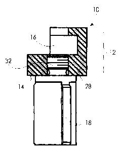
Figure 1 is partial cross-sectional view of a
Relayair control valve that is part of a 26L locomotive
braking system which includes the prior art valve seat
and sealing member.
Figure 2 is an enlarged partial cross-sectional view
of prior art illustrated in Figure 1.
Figure 3 is a partial cross-sectional view of a
presently preferred embodiment of the present invention
as it would be used in a 26-L relay valve.
DETAILED DESCRIPTION OF THE INVENTION
6

CA 02394498 2002-07-23
Before describing the present invention in detail,
for the sake of clarity and understanding, the reader is
advised 'that identical components having identical
functions ~~in each of the accompanying drawings have been
marked with the same reference numerals throughout each
of the several figures illustrated herein.
Figure 1 shows the valve seat apparatus, generally
designated 30, of the prior art attached to stem 24,
which is engaged by diaphragm 28. Attached to valve seat
apparatus-30 is valve seat guide 18. In Figure 2, valve
seat guide 18 is shown in detail as threadably attached
to carrier 22. Carrier 22 is formed from a metallic or
similarly suitable material and a sealing member,
generally designated 20, formed from rubber or a suitable
elastomer, is joined to carrier 22.
Reference is now made, more particularly, to
Figure 3. Illustrated thereon is a valve seat assembly,
generally designated 10. Valve seat assembly 10 includes
valve seat apparatus. 12, formed from one contiguous
material, preferably polytetrafluoroethylene (PTFE) with
a 25°s glass filler. Valve seat apparatus 12 includes
sealing surface 14 and recessed area 16. Recessed
7

CA 02394498 2002-07-23
area '16 is machined or formed into valve seat
apparatus 12 to provide a means of connection to '
actuating stem 24 engageable with a diaphragm or moveable
by a solenoid in a valve. Recessed area 16 is generally
shaped to fit to a formed area at the end of the
actuating stem 24, such as is found on a Relayair valve
on a 26-L braking system. Threads 32 are formed into
carrier portion 28 to allow for attachment of guide 18.
The lower surface of carrier portion 28, shown as sealing
surface 14, is not a separate component but is suitably
machined, polished or otherwise finished into the lower
face of the carrier portion 28 so as to suitably mate
with the corresponding sealing seat of a valve.
Consequently, other than the threadably attached
guide 18, the valve seat apparatus 10 is formed as one
contiguous component. The preselected plastic material
of which the valve seat apparatus 10 is composed may be
made from either a petroleum based elastomer, a synthetic
elastomer, a 'natural elastomer or various combinations
thereof. The material selected may be combined with a
filler to enhance or manifest desired physical
properties. Also, the material selected generally must
8

CA 02394498 2002-07-23
possess sufficient lubricity to allow relatively free
movement -of the valve seat apparatus 10 within the valve
body.
The present invention has been set forth in detail
according to the Patent Act, and those persons of
ordinary skill in the technical art to which this
invention pertains will recognize various alternative
ways of practicing the invention without departing from
the spirit and scope of the appended claims. Those of
ordinary ~ kill in the relevant art will also recognize
that the foregoing description is merely illustrative and
is not intended to limit any of the following claims to
any particular narrow interpretation.
9

Representative Drawing
A single figure which represents the drawing illustrating the invention.
Administrative Status

2024-08-01:As part of the Next Generation Patents (NGP) transition, the Canadian Patents Database (CPD) now contains a more detailed Event History, which replicates the Event Log of our new back-office solution.

Please note that "Inactive:" events refers to events no longer in use in our new back-office solution.

For a clearer understanding of the status of the application/patent presented on this page, the site Disclaimer , as well as the definitions for Patent , Event History , Maintenance Fee  and Payment History  should be consulted.

Event History

Description Date
Inactive: IPC from MCD 2006-03-12
Application Not Reinstated by Deadline 2005-12-15
Inactive: Dead - No reply to s.30(2) Rules requisition 2005-12-15
Deemed Abandoned - Failure to Respond to Maintenance Fee Notice 2005-07-25
Inactive: Abandoned - No reply to s.30(2) Rules requisition 2004-12-15
Inactive: S.30(2) Rules - Examiner requisition 2004-06-15
Application Published (Open to Public Inspection) 2003-07-14
Inactive: Cover page published 2003-07-13
Inactive: First IPC assigned 2002-09-30
Amendment Received - Voluntary Amendment 2002-09-16
Application Received - Regular National 2002-09-03
Letter Sent 2002-09-03
Inactive: Filing certificate - RFE (English) 2002-09-03
Request for Examination Requirements Determined Compliant 2002-07-23
All Requirements for Examination Determined Compliant 2002-07-23

Abandonment History

Abandonment Date Reason Reinstatement Date
2005-07-25

Maintenance Fee

The last payment was received on 2004-07-05

Note : If the full payment has not been received on or before the date indicated, a further fee may be required which may be one of the following

  • the reinstatement fee;
  • the late payment fee; or
  • additional fee to reverse deemed expiry.

Patent fees are adjusted on the 1st of January every year. The amounts above are the current amounts if received by December 31 of the current year.
Please refer to the CIPO Patent Fees web page to see all current fee amounts.

Fee History

Fee Type Anniversary Year Due Date Paid Date
Request for examination - standard 2002-07-23
Registration of a document 2002-07-23
Application fee - standard 2002-07-23
MF (application, 2nd anniv.) - standard 02 2004-07-23 2004-07-05
Owners on Record

Note: Records showing the ownership history in alphabetical order.

Current Owners on Record
WESTINGHOUSE AIR BRAKE TECHNOLOGIES CORPORATION
Past Owners on Record
JEFFREY B. GLASGOW
WILLIAM ZERAVICA
Past Owners that do not appear in the "Owners on Record" listing will appear in other documentation within the application.
Documents

To view selected files, please enter reCAPTCHA code :


To view images, click a link in the Document Description column (Temporarily unavailable). To download the documents, select one or more checkboxes in the first column and then click the "Download Selected in PDF format (Zip Archive)" or the "Download Selected as Single PDF" button.

List of published and non-published patent-specific documents on the CPD .

If you have any difficulty accessing content, you can call the Client Service Centre at 1-866-997-1936 or send them an e-mail at CIPO Client Service Centre.

({010=All Documents, 020=As Filed, 030=As Open to Public Inspection, 040=At Issuance, 050=Examination, 060=Incoming Correspondence, 070=Miscellaneous, 080=Outgoing Correspondence, 090=Payment})


Document
Description 
Date
(yyyy-mm-dd) 
Number of pages   Size of Image (KB) 
Abstract 2003-07-13 1 17
Representative drawing 2002-10-20 1 7
Description 2002-07-22 1 17
Description 2002-07-22 9 268
Claims 2002-07-22 6 127
Drawings 2002-07-22 2 29
Drawings 2002-09-15 2 35
Acknowledgement of Request for Examination 2002-09-02 1 177
Courtesy - Certificate of registration (related document(s)) 2002-09-02 1 112
Filing Certificate (English) 2002-09-02 1 163
Reminder of maintenance fee due 2004-03-23 1 109
Courtesy - Abandonment Letter (R30(2)) 2005-02-22 1 166
Courtesy - Abandonment Letter (Maintenance Fee) 2005-09-18 1 173