Note: Descriptions are shown in the official language in which they were submitted.
CA 02394998 2002-06-06
WO 01/56674 PCT/USO1/02125
1
TOY MOTORCYCLE CONFIGURABLE AS A HOVERCYCLE
SPECIFICATION
Field of the Invention
This invention relates generally to toys and toy
figures and particularly to those which are capable of
being configured in alternate configurations and
appearances.
Backqround of the Invention
Toys which are configurable between alternate
appearances and configurations are well known in the
art. Such toys are characterized by a first
configuration such as a toy vehicle or the like.
Typically, such toys are formed of a plurality of
articulated elements movable in various combinations
and directions to assume a first configuration and
appearance. Such toys are further characterized by
the ability to move the plurality of articulated
elements to form a second configuration usually
exhibiting a different appearance such as a robot or
the like. One of the important characteristics of
such configurable toys is the use of elements which
are capable of moving to assume an alternate shape of
the toy. In most such configurable toys, the elements
are formed of molded plastic and usually exhibit a
highly stylized appearance. For maximum play value
and amusement, the configurations are generally chosen
to exhibit a substantially different type of toy. For
CA 02394998 2002-06-06
WO 01/56674 PCT/USO1/02125
2
example, US Patent 4,571,203 issued to Murakami sets
forth a FORM-CONVERTIBLE TOY ROBOT which includes a
plurality of body parts such as head, arms, shoulders,
thighs and legs to form a robot which are variously
articulated to reconfigure the toy into a toy
motorcycle.
US Patent 4,529,391 issued to Hoshino et al. sets
forth a TOY HAVING TWO MODES OF LOCOMOTION in which a
rotatable fly wheel motor is positioned within a toy
motorcycle. The toy motorcycle is formed of a
plurality of movable elements which may be moved to
alternate configurations and thereby form a fanciful
creature. The second mode of appearance is also
characterized by an alternative mode of propulsion
using the appendages.
US Patents Des.281,087 and Des.281,001 both
issued to Ohno and both entitled RECONFIGURABLE TOY
VEHICLE set forth similar designs for a toy vehicle
which is alternately configurable as a robot.
US Patent Des.281,088 issued to Murakami sets
forth a TOY ROBOT CONVERTIBLE INTO AUTOBIKE which is
substantially identical to the above referenced US
Patent 4,571,203.
US Patent Des.285,466 issued to Ohno sets forth a
RECONFIGURABLE TOY VEHICLE having a first appearance
and configuration simulating a military toy vehicle
commonly known as a "jeep" and an alternate
configuration resembling a fanciful robot.
CA 02394998 2002-06-06
WO 01/56674 PCT/USO1/02125
3
US Patent Des.286,800 issued to Maruyama sets
forth a RECONFIGURABLE TOY HAWK having a spherical toy
formed of a plurality of articulated members which
reconfigure to a fanciful depiction of a hawk-like
creature.
US Patent Des.296,801 issued to Matsumoto and
entitled RECONFIGURABLE TOY AUTO BIKE and US Patent
Des.301,359 issued to Shinohara entitled
RECONFIGURABLE TOY BIKE sets forth toy motorcycles
which are reconfigurable into fanciful robot-like
creatures. US Patent Des.303,412 issued to Matsuda
sets forth a RECONFIGURABLE TOY JEEP/HELICOPTER having
a first configuration resembling a helicopter like
vehicle and a second configuration resembling a
military vehicle known as a jeep.
US Patent 4,580,993 issued to Ohno sets forth a
RECONFIGURABLE TOY ASSEMBLY having alternate
configurations resembling a robot and a pick-up truck
like toy vehicle.
US Patent 4,516,948 issued to Obara sets forth a
RECONFIGURABLE TOY ASSEMBLY capable of forming a
tractor-trailer toy vehicle and a robot.
US Patent 4,578,046 issued to Ohno sets forth a
REVERSIBLE TRANSFORMABLE TOY BLOCK ASSEMBLY sets forth
a toy vehicle formed of multiply articulated
components which are reconfigurable to form a robot.
Several design patents show various different
appearance designs for toy motorcycles. For example,
US Patent Des.276,251 issued to Wykimura and US Patent
CA 02394998 2002-06-06
WO 01/56674 PCT/USO1/02125
4
Des.340,757 issued to Chen each entitled TOY
MOTORCYCLE shown different appearances for toy
motorcycles.
Additional toy motorcycle designs are shown in US
Patent Des.281,795 issued to Shimomura and US Patent
Des.280,750 issued to Toshimasa and US Patent
Des.281,796 issued to Shimomura and US patent
Des.280,751 issued to Toshimasa all of which are
entitled TOY MOTORCYCLE.
US Patents Des.276,059 and Des.276,060 both
issued to Smollar et al. and both entitled TOY
MOTORCYCLE show similar appearance toy motorcycles.
While the foregoing described prior art device
have to some extent improved the art and in some
instances enjoyed commercial success, there remains
nonetheless a continuing need in art for evermore
amusing, entertaining and improved toy motorcycles
configurable in alternate toy shapes and
configurations.
Summary of the Invention
Accordingly, it is a general object of the
present invention to provide an improved toy
motorcycle. It is a more particular object of the
present invention to provide an improved toy
motorcycle which is configurable into an alternate
toy. It is a still more particular object of the
present invention to provide an improved toy
motorcycle which is alternately configurable as a
hovercycle.
CA 02394998 2002-06-06
WO 01/56674 PCT/USO1/02125
In accordance with the present invention there is
provided a toy motorcycle configurable between a
motorcycle configuration and a hovercycle
5 configuration, the toy motorcycle comprising: a body
having a chassis box therein; a pair of chassis shafts
pivotally supported by the chassis box each shaft
having a front end and a rear end; a pair of front
fork halves each supported by the front ends of the
chassis shafts; a pair of front wheel halves each
supported by the front fork halves; a pair of rear
fork halves each supported by the rear ends of the
chassis shafts; a pair of rear wheel halves each
supported by the rear fork halves; and means for
pivoting the chassis shafts between a first position,
in which the front and rear fork halves and the front
and rear wheel halves are in contact defining the
motorcycle configuration, and a second position in
which the front and rear fork halves and the front and
rear wheel halves extend outwardly defining the
hovercycle configuration.
Brief Description of the Drawings
The features of the present invention, which are
believed to be novel, are set forth with particularity
in the appended claims. The invention, together with
further objects and advantages thereof, may best be
understood by reference to the following description
taken in conjunction with the accompanying drawings,
in the several figures of which like reference
numerals identify like elements and in which:
CA 02394998 2002-06-06
WO 01/56674 PCT/USO1/02125
6
Figure 1 sets forth a side elevation view of the
present invention toy motorcycle in its motorcycle
configuration;
Figure 2 sets forth a bottom plan view of the
present invention toy motorcycle configured in its
alternate hovercycle configuration;
Figure 3 sets forth a partial side elevation view
of the internal support mechanism of the present
invention toy motorcycle;
Figure 4 sets forth a partial section view of the
present invention motorcycle taken along section line
4-4 in Figure 3;
Figure 5 sets forth a partial section view of the
present invention toy motor cycle taken along section
lines 5-5 in Figure 3;
Figure 6 sets forth a partial section view of the
present invention toy motorcycle taken along section
lines 5-5 in Figure 3 showing the present invention
toy motorcycle in its hovercycle configuration.
Description of the Preferred Embodiment
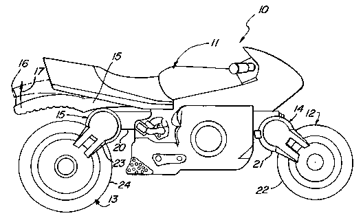
Figure 1 sets forth a side elevation view of a
toy motorcycle constructed in accordance with the
present invention and generally referenced by numeral
10. Motorcycle 10 includes a body 11 preferably
formed of a molded plastic material or the like.
Motorcycle 10 further includes a chassis shaft 20
having an elongated cylindrical shape extending
CA 02394998 2002-06-06
WO 01/56674 PCT/USO1/02125
7
through body 11. Motorcycle 10 further includes a
front fork 14 and a front wheel 12 supported by
chassis shaft 20 together with a rear wheel 13 and a
rear fork 15 also supported by shaft 20. As is better
seen in Figure 2 below, front wheel 12 is formed of
wheel halves 22 and 32 while rear wheel 13 is
similarly formed of wheel halves 24 and 34. In
addition, front fork 14 and rear fork 15 are formed of
fork halves 21 and 31 and 23 and 33 respectfully (also
seen in Figure 2). A lever 15 is pivotally supported
by body 11 in the manner set forth below in greater
detail. Lever 15 includes and outer end 16 which is
movable with respect to body 11 upwardly in the
direction indicated by arrow 17 to the dash-line
position indicated in Figure 1.
In accordance with the present invention,
motorcycle 10 when configured in its motorcycle
configuration shown in Figure 1 is capable of
conventional toy motorcycle play by the child user.
Thus, motorcycle 10 may be rolled about on front wheel
12 and rear wheel 13 as the child user plays with the
toy motorcycle. In accordance with a further
advantage of the present invention, end 16 of lever 15
may be pivoted upwardly in the direction indicated by
arrow 17 to transform motorcycle 10 to its hovercycle
configuration shown in Figure 2. As the child user
releases end 16 of lever 15, motorcycle returns to the
conventional motorcycle configuration of Figure 1.
Figure 2 sets forth a bottom view of toy
motorcycle 10 configured in is alternate configuration
in which motorcycle 10 forms a hovercycle. A
hovercycle is a fanciful device in which a plurality
CA 02394998 2002-06-06
WO 01/56674 PCT/USO1/02125
8
of downwardly directed power driven fans or propellers
produce sufficient downward force to levitate the
vehicle. While toy motorcycle 10 is not operational
in this manner, the alternate configuration of the
present invention toy motorcycle shown in Figure 2
does provide a fanciful depiction of this hovercycle.
More specifically, motor cycle 10 includes a body
11 supporting a pair of chassis shafts 20 and 30 which
are rotatably supported by body 11 in the manner
described below. Suffice it to note here; that
chassis shaft 20 extends through body 11 in a front-
to-back orientation and supports a pair of fork halves
21 and 23 at each end thereof. Fork half 21 supports
a wheel half 22 which is rotatably secured to fork
half 21 by a conventional fastener 41. Fastener 41
serves as a rotation axle in the manner best seen in
Figure 6. Wheel half 22 further defines an annular
groove 25 and an annular surface 27. Similarly, fork
half 23 rotatably supports a wheel half 24 using a
fastener axle 43. Wheel half 24 defines an annular
groove 26 and an annular surface 28.
In a similar fashion, chassis shaft 30 supports
fork halves 31 and 33 at each end thereof. Fork half
31 supports a wheel half 32 using a fastener 40 as a
rotation axle. Wheel half 32 further defines an
annular rib 35 and an annular surface 37. Fork half
33 further supports a wheel half 34 in a rotatable
attachment using fastener 42 as an axle and fastener.
Wheel half 34 further defines a rib 36 and an annular
surface 38.
CA 02394998 2002-06-06
WO 01/56674 PCT/USO1/02125
9
An elongated lever 15 having an end 16 is
supported within body 11 in the manner shown in Figure
3.
In the hovercycle configuration of motorcycle 10
shown in Figure 2, the outward pivotal movements of
chassis shafts 20 and 30 induced by movement of lever
in the manner set forth below in Figures 5 and 6
splits the respective wheel halves of front wheel 12
10 and rear wheel 13 into outwardly extending simulated
hover producing devices replicated by wheel halves 22
and 32 in front and wheel halves 24 and 34 in the rear
of motorcycle 10. Thus, in this configuration, body
11 appears to be supported by a quartet of downwardly
15 directed hover producing apparatus for fanciful play
by the child user.
To further enhance the standard motorcycle
appearance of toy motorcycle 10, wheel half 22 defines
an annular groove 25 while wheel half 32 defines an
annular rib 35. When wheel halves 22 and 32 are
joined at surfaces 27 and 37 to form front wheel 12
(seen in Figure 1) rib 35 is received within groove 25
to further enhance this joining of wheel halves to
form a standard appearing front wheel. Similarly,
wheel half 24 defines an annular groove 26 while wheel
half 34 defines an annular rib 36. Thus, wheel halves
24 and 34 join to form wheel 13 as rib 36 is received
within groove 26 allowing surfaces 28 and 38 to be in
flush contact.
Figure 3 sets forth a partially sectioned side
elevation view of motorcycle 10 configured in its
motorcycle configuration in which body 11 is shown in
CA 02394998 2002-06-06
WO 01/56674 PCT/USOi/02125
dashed outline to allow illustration of the internal
support mechanism of the toy motorcycle. Body 11
supports a chassis box 45 which in turn defines a
front journal 47 and a rear journal 46. An elongated
5 chassis shaft 20 is rotatably supported within
journals 46 and 47 and defines a pair of flanges 50
and 52 to maintain the positioning of chassis shaft
within chassis box 45. Chassis shaft 20 supports a
fork half 21 which in turn supports a wheel half 22.
10 Chassis shaft 20 also supports a fork half 23 which in
turn supports a wheel half 24.
A lever 15 having an end 16 and an end 29 is
pivotally supported upon body 11 in the manner best
seen in Figure 4 by a pivot mechanism 18. Thus, the
pivotal support of lever 15 allows end 16 to be moved
upwardly in the direction indicated by arrow 17
causing a corresponding downward movement of end 29 in
the direction indicated by arrow 19.
As is better seen in Figure 2, body 11 supports a
pair of chassis shafts 20 and 30 in a generally
parallel arrangement. Chassis shaft 20 further
defines a spring cam 51 and a lever cam 55. Chassis
box 45 further defines an upwardly extending stop 53
while chassis shaft 20 defines a stop tab 54. Stop
tab 54 and stop 53 cooperate to limit the pivotal
movement of chassis shaft 20 within chassis box 45 in
the inwardly pivoting movement to the position shown
in Figure 3.
Chassis box 45 further includes a shaft 48 which
in turn supports a spring 49. Spring 49 engages
spring cam 51 of shaft 20 producing a spring force
CA 02394998 2002-06-06
WO 01/56674 PCT/USO1/02125
11
which urges rotation of shaft 20 toward the inward
position shown in Figures 1 and 3 corresponding to the
standard motorcycle configuration of toy motorcycle
l0. A second spring cam 61 is supported by shaft 30
(seen in Figure 4). A second lever cam 65 is also
supported by chassis shaft 30 (seen in Figure 5). Of
importance to note in Figure 3, is the operation by
which the upward movement of end 16 of lever 15 in the
direction of arrow 17 forces end 29 of lever 15
downwardly in the direction of arrow 19 against lever
cams 55 and 65. With temporary reference to Figures 5
and 6, it will be noted that this movement of lever 15
and the resulting outward rotations of chassis shafts
and 30 (seen in Figure 5) forces the respective
15 wheel halves of front wheel 12 and rear wheel 13
outwardly to the alternate configuration shown in
Figures 2 and 6.
Figure 4 sets forth a partial section view of toy
20 motorcycle 10 taken along section lines 4-4 in Figure
3. As described above, body 11 supports a chassis box
45 within which a shaft 48 is supported. Shaft 48
supports a portion of spring 19. A shaft 78 is also
supported within chassis box 45 and further supports
spring 49. A chassis shaft 20 is rotatably supported
within chassis box 45 and includes a stop tab 54 and a
spring cam 51. Similarly, a chassis 30 is rotatably
supported within chassis box 45 and includes a stop
tab 64 and a spring cam 61. The upwardly extending
end portions of spring 49 exert a force against spring
cams 51 and 61 which urge rotation of chassis shafts
20 and 30 in the directions indicated by arrows 75 and
76.
CA 02394998 2002-06-06
WO 01/56674 PCT/USO1/02125
12
A rear wheel 13 is formed of a pair of wheel
halves 24 and 34 supported by chassis shafts 20 and 30
respectively in the manner shown in Figure 2. Wheel
half 24 defines a groove 26 and a surface 28.
Correspondingly, wheel half 34 defines a rib 36
received within groove 26 and a surface 38 received
upon surface 28 of wheel half 24. In this manner,
rear wheel 13 is formed of a pair of rotatable wheel
halves 24 and 34.
Body 11 further includes a pivot mechanism 18
which pivotally supports a lever 15 in the manner set
forth above in Figure 3.
Thus, in the section view of Figure 4, the
cooperation between spring 49 and spring cams 51 and
61 is operative upon chassis shafts 20 and 30 to
maintain toy motorcycle 10 in its standard
configuration as illustrated in Figure 1. It will be
apparent that a residual spring force is provided by
spring 49 tending to maintain the closure of wheel
halves 34 and 24. While not shown in Figure 4, it
will be understood that the similar attachment of
wheel halves 22 and 32 which form front wheel 12 are
also maintained in their closed position by the action
of spring 49 upon spring cams 51 and 61.
Figure 5 sets forth a partial section view of toy
motorcycle l0 taken along section lines 5-5 in Figure
3. As described above, toy motorcycle 10 includes a
chassis box 45 having supporting journals 47 and 77
formed therein. Chassis box 45 further defines a pair
of upwardly extending stops 53 and 63. A chassis
shaft 20 is rotatably supported within journal 47 of
CA 02394998 2002-06-06
WO 01/56674 PCT/USO1/02125
13
chassis box 45 and maintained in position by a flange
52. Chassis shaft 20 further includes a lever cam 55
having a curved outer surface and extending inwardly
from chassis shaft 20. A chassis shaft 30 is
rotatably supported within journal 47 and includes a
flange 62 maintaining the position of chassis shaft 30
within chassis box 45. Chassis shaft 30 further
includes an inwardly extending lever cam 65 having a
curved outer surface and a flange 62 maintaining the
position of chassis shaft 30. Chassis shafts 20 and
30 define respective stop tabs 54 and 64. Tabs 54 and
64 cooperate with stops 53 and 63 respectively to
limit the pivoting movement of chassis shafts 20 and
30 in the directions indicated by arrows 80 and 81.
Front wheel 12 is formed of a pair of wheel
halves 22 and 32 supported upon chassis shafts 20 and
30 respectively in the manner shown in Figure 2. As
described above, the pivotal position of shafts 20 and
30 is urged toward the closed configuration of Figure
1 by the action of spring 49 against spring cams 51
and 61. Returning to Figure 5, the rotational
direction urged upon chassis shafts 20 and 30
corresponds to arrows 80 and 81. Accordingly, wheel
halves 22 and 32 are maintained in closure to form
front wheel 12.
In accordance with the present invention, the
user is able to reconfigure toy motorcycle 10 by
forcing end 29 of lever 15 downwardly against lever
cams 55 and 65 in the manner seen in Figure 6. This
downward force upon lever cams 55 and 65 produces a
corresponding rotation of chassis shafts 20 and 30 in
the directions indicated by arrows 82 and 83. Thus,
CA 02394998 2002-06-06
WO 01/56674 PCT/L1S01/02125
14
as end 29 of lever 15 is forced downwardly upon lever
cams 55 and 65, motorcycle 10 is reconfigured in the
manner shown in Figure 6.
Figure 6 sets forth the section view of Figure 5
following the above described movement of lever 15
causing reconfiguration of motorcycle 10 to its
hovercycle configuration. Also shown in Figure 6, are
partial section views of wheel halves 22 and 32.
More specifically, motorcycle l0 includes a
chassis box 45 supported within body 11 (seen in
Figure 1). Chassis box 45 defines a pair of journals
47 and 77 which rotatably support chassis shafts 20
and 30. Chassis box 45 further includes a pair of
upwardly extending stops 53 and 63. Chassis shaft 20
includes a flange 52 and a lever cam 55. Chassis
shaft 20 further supports a fork half 21 which in turn
supports a wheel half 22 using a fastener axle 41.
Wheel half 22 defines an annular groove 25 and an
annular surface 27.
Chassis shaft 30 includes a flange 62 and a lever
cam 65. Chassis shaft 30 further supports a fork half
31 which in turn rotatably supports a wheel half 32
using fastener axle 40. Wheel half 32 defines an
annular rib 35 and an annular surface 37. Chassis
shafts 20 and 30 further define stop tabs 54 and 64
respectively.
A lever 15 includes an end 29 and is pivotally
supported within body 11 in the manner shown in Figure
3. In operation, as the above described movement of
lever 15 is implemented as the user forces end 16 of
CA 02394998 2002-06-06
WO 01/56674 PCT/USO1/02125
lever 15 upwardly in the direction indicated by arrow
17 in Figure 3, a corresponding downward movement of
end 29 in the direction indicated by arrow 71 occurs.
This downward movement forces lever cams 55 and 65 to
5 pivot downwardly as indicated by arrows 84 and 85. A
corresponding pivotal movement of chassis shafts 20
and 30 results causing wheel halves 22 and 32 to pivot
outwardly and upwardly in the directions indicated by
arrows 72 and 73 respectively. At this point,
10 motorcycle 10 has been reconfigured to the hover cycle
shown in Figure 2. It will be recalled that the
cooperation of spring cams 51 and 61 together with
spring 49 in the manner shown in Figure 4 urges shafts
and 30 toward the closed configuration of Figure 5.
15 Thus, it will be understood that the outward pivotal
movement of wheel halves 22 and 32 shown in Figure 6
is accomplished to the opposition to spring 49 (seen
in Figure 4). Thus, when the user releases lever 15,
the action of spring 49 and spring cams 51 and 61
20 (seen in Figure 4) returns motorcycle 10 to closed
configuration shown in Figure 1.
While particular embodiments of the invention
have been shown and described, it will be obvious to
those skilled in the art that changes and
modifications may be made without departing from the
invention in its broader aspects. Therefore, the aim
in the appended claims is to cover all such changes
and modifications as fall within the true spirit and
scope of the invention.