Note: Descriptions are shown in the official language in which they were submitted.
CA 02395031 2002-07-25
JJ-11 703CA
TITLE: Jet-Propelled Watercraft
FIELD OF THE INVENTION
The present invention relates to a jet
s propelled watercraft in which a jet nozzle for jetting
water is provided at a stern, a steering nozzle is
additionally provided for the jet nozzle, and a reverse
bucket is vertically swingably provided behind the
steering nozzle.
BACKGROUND OF THE INVENTION
Jet-propelled watercrafts have been known, for
example, from Japanese Patent No. 3121333 entitled "Water
Jet propulsion unit". The jet-propelled watercraft
disclosed in this document will be described in detail
with reference to the following figure (FIG. 14) recited
from FIG. 3 in this document. It is to be noted that
reference numerals are newly given in the following
figure for the sake of convenience.
FIG. 14 is a side view showing an essential
portion of the related art jet-propelled watercraft
disclosed in the above-described document. A jet-
propelled watercraft 100 includes a jet propulsion unit
101 at a stern. A steering nozzle 102 is provided behind
the jet propulsion unit 101 in such a manner as to be
swingable in the lateral direction around upper and lower
supporting shafts 103. A reverse bucket 104 is provided
behind the steering nozzle 102 in such a manner as to be
swingable in the vertical direction around left and right
supporting shafts 105.
In the case of propelling the jet-propelled
watercraft 100 forward, an operating cable 106 is
operated, to swing the reverse bucket 104 around the
supporting shafts 105 as shown by an arrow, thereby
shifting the reverse bucket 104 to a forward position P3
-~1 -
CA 02395031 2002-07-25
JJ-11 703CA
located over the steering nozzle 102, with a result that
a water stream is jetted rearward from an outlet 102a of
the steering nozzle 102, to propel the jet-propelled
watercraft forward.
In the case of propelling the jet-propelled
watercraft 100 in reverse, the operating cable 106 is
operated, to swing the reverse bucket 104 around the
supporting shafts 105, thereby shifting the reverse
bucket 104 to a reverse position P4 on the outlet 102a
side of the steering nozzle 102, that is, the position
shown in FIG. 14, with a result that a water stream
jetted from the outlet 102a of the steering nozzle 102 is
introduced forward as shown by an arrow, to propel the
jet-propelled watercraft 100 in reverse.
In addition, a tensile spring 107 is used as
means for holding the reverse bucket 104 at the forward
position P3 and the reverse position P4.
The jet-propelled watercraft 100 shown in FIG.
14 has a problem that since the operating cable 106 for
operating the reverse bucket 104 must be disposed over
the jet propulsion unit 101, a containing space 108 for
disposing the operating cable 106 is required to be
ensured over the jet propulsion unit. This obstructs the
lowering of the center of gravity of the jet-propelled
watercraft 100.
An object of the present invention is to
provide a jet-propelled watercraft capable of eliminating
the need of disposition of an operating cable connected
to a reverse bucket in a space over a jet propulsion unit
SUMMARY OF THE INVENTION
To solve the above-described problem, according
to the present invention, there is provided a jet-
propelled watercraft, wherein a jet nozzle for jetting
water is provided at a stern, a steering nozzle is
w~
- 2 -
CA 02395031 2002-07-25
JJ-11 703CA
is additionally provided for the jet nozzle, a lower side
of the steering nozzle is covered with a ride plate
removably mounted to a hull, a pair of supporting
brackets are provided on left and right sides of the ride
plate, and a reverse bucket is vertically swingably
provided on the pair of supporting brackets. This jet-
propelled watercraft is characterized in that an
intermediate lever is disposed in a gap between one of
the pair of supporting brackets and the steering nozzle,
the intermediate lever is swingably mounted to the one of
the supporting brackets, and an operating cable is
connected to the reverse bucket via the intermediate
lever, whereby the reverse bucket is swung by operating
the intermediate lever via the operating cable.
With this configuration, the intermediate lever
is disposed in the gap between one of the supporting
brackets and the steering nozzle and the operating cable
is connected to the reverse bucket via the intermediate
lever. As a result, since the operating cable can be
disposed along a side surface of the jet propulsion unit,
it is possible to eliminate the need of disposition of
the operating cable connected to the reverse bucket in a
space over the jet propulsion unit.
Since the pair of supporting brackets are
provided on the left and right sides of the ride plate
and the intermediate lever is disposed in the gap between
one of the supporting brackets and the steering nozzle,
it is possible to ensure a wider gap between the pair of
supporting bracket and hence to widen a width of the
reverse bucket.
In addition, since the gap between the pair of
supporting brackets can be widened, it is possible to
ensure a space being large enough to rigidly form
supporting portions of the reverse bucket.
..
- 3
CA 02395031 2002-07-25
JJ-11 703CA
BRIEF DESCRIPTION OF THE DRAWINGS
Preferred embodiments of the invention are
shown in the drawings, wherein:
FIG. 1 is a side view of a jet-propelled
watercraft according to the present invention.
FIG. 2 is a side view showing an essential
portion of the jet-propelled watercraft according to the
present invention.
FIG. 3 is an exploded side view showing an
essential portion of the jet-propelled watercraft
according to the present invention.
FIG. 4 is an exploded plan view showing an
essential portion of the jet-propelled watercraft
according to the present invention.
FIG. 5 is an enlarged view of an essential
portion shown in FIG. 2.
FIGS. 6(a) and 6(b) are views illustrating a
first operation of the jet-propelled watercraft according
to the present invention.
FIGS. 7(a) and 7(b) are views illustrating a
second operation of the jet-propelled watercraft
according to the present invention.
FIGS. 8(a) and 8(b) are views illustrating a
third operation of the jet-propelled watercraft according
to the present invention.
FIGS. 9(a) and 9(b) are views illustrating a
fourth operation of the jet-propelled watercraft
according to the present invention.
FIGS. 10(a) and 10(b) are views illustrating a
fifth operation of the jet-propelled watercraft according
to the present invention.
FIGS. 11(a) and 11(b) are views illustrating a
sixth operation of the jet-propelled watercraft according
to the present invention.
- ~4 -
CA 02395031 2002-07-25
JJ-11 703CA
FIG. 12 is a view illustrating a seventh
operation of the jet-propelled watercraft according to
the present invention.
FIGS. 13(a) and 13(b) are views illustrating
the j.et-propelled watercraft according to the present
invention in comparison with a related art jet-propelled
watercraft.
FIG. 14 is a side view showing an essential
portion of the related art jet-propelled watercraft.
DETAILED DESCRIPTION OF THE PREFERRED EMBODIMENTS
Hereinafter, an embodiment of the present
invention will be described with reference to the
accompanying drawings. It is to be noted that the
drawings should be viewed along the direction of
characters.
FIG. 1 is a side view of a jet-propelled
watercraft according to an embodiment of the present
invention.
A jet-propelled watercraft 10 shown in FIG. 1
includes a hull 11. In the hull 11, a fuel tank 14 is
mounted at a front portion 12 of the hull 11, an engine
15 is provided behind the fuel tank 14, and a jet
propulsion unit chamber 16 is provided behind the engine
15. In the jet propulsion unit chamber 16, a jet
propulsion unit 20 is disposed at a stern 11a of the hull
11.
In this jet-propelled watercraft 10, a rear
portion of the jet propulsion unit 20 is configured as a
jet nozzle 24 which has a steering nozzle 30 additionally
mounted thereto. A lower side of the steering nozzle 30
is covered with a ride plate 34 removably mounted to the
hull 11. A pair of left and right supporting brackets 35
and 36 are provided on left and right sides of the ride
plate 34, respectively. A reverse bucket 40 is
-' 5 -
CA 02395031 2002-07-25
JJ-11 703CA
vertically swingably provided on these left and right
supporting brackets 35 and 36. A steering handlebar 18
is provided in front of a seat 17 at a position over the
fuel tank 14, and an operating lever 60 for operating the
reverse bucket 40 is provided under the operating
handlebar 18.
The jet propulsion unit 20 has a housing 21
extending rearwardly from a suction port 13a formed in a
bottom shell 13. An impeller 22 is rotatably mounted in
the housing 21 in such a manner as to be connected to a
drive shaft 23 of the engine 15.
The steering nozzle 30 is a member laterally
swingably mounted to a rear end of the housing 21 (that
is, an outlet of the jet nozzle 24). Since the steering
handlebar 18 is connected to the steering nozzle 30 via
an operating cable as described above, the steering
nozzle 30 can be laterally swung by operating the
steering handlebar 18.
The reverse bucket 40 is a member swingably
mounted to the left and right supporting brackets 35 and
36 provided on the left and right sides of the ride plate
34. The jet-propelled watercraft 10 can be propelled
forward by shifting the reverse bucket 40 to a forward
position P1 located over the steering nozzle 30. On the
other hand, the jet-propelled watercraft 10 can propelled
in reverse by shifting the reverse bucket 40 to a reverse
position P2 located behind the steering nozzle 30.
The operating lever 60 is connected to the
reverse bucket 40 via an operating cable 41.
Accordingly, the reverse bucket 40 can be vertically
swung by operating the operating lever 60.
The jet-propelled watercraft 10 is propelled
forward by shifting the reverse bucket 40 to the forward
position P1 located over the steering nozzle 30, and then
supplying fuel from the fuel tank 14 to the engine 15 to
_ .,6 _
CA 02395031 2002-07-25
JJ-11 703CA
drive the engine 15 and transmitting a drive force of the
engine 15 to the impeller 22 via the drive shaft 23.
The impeller 22, to which the drive force of
the engine 15 has been transmitted, is rotated to suck
water from the suction port 13a of the bottom shell 13,
and to jet the sucked water as a water jet stream from an
outlet 31' of the steering nozzle 30 via a rear end of
the housing 21, that is, an outlet 25 of the jet nozzle
24.
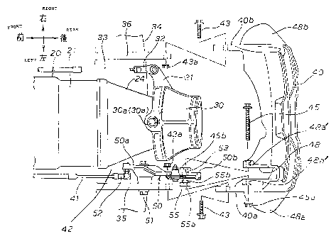
FIG. 2 is a side view showing an essential
portion of the jet-propelled watercraft according to the
present invention. This figure shows a state that the
steering nozzle 30 is additionally mounted to the jet
nozzle 24 at the rear portion of the jet propulsion unit
20, the lower side of the steering nozzle 30 is covered
with the ride plate 34 removably provided on the hull 11,
the left and right supporting brackets 35 and 36 are
provided on the left and right sides of the ride plate 34
respectively, and the reverse bucket 40 is vertically
swingably provided on the left and right brackets 35 and
36.
The jet-propelled watercraft 10 has a feature
that an intermediate lever 50 is disposed in a gap 42
(shown in FIG. 4) between one of the left and right
supporting brackets 35 and 36 (left supporting bracket 35
in the example shown in the figures) and the steering
nozzle 30. The intermediate lever 50 is swingably
mounted to the left supporting bracket 35. The operating
cable 41 is connected to the reverse bucket 40 via the
intermediate lever 50. The operating lever 60 is mounted
to a front end 41a of the operating cable 41.
V~Then the operating lever 60 is vertically swung
around a supporting shaft 61, the intermediate lever 50
is vertically swung around a supporting bolt 51 by
operating the operating cable 41. With this swing motion
_.7 _
CA 02395031 2002-07-25
JJ-11 703CA
of the intermediate lever 50, the reverse bucket 40 can
be vertically swung around a supporting bolt 43.
As a result, the reverse bucket 40 can be
shifted from the forward position P1 located above the
steering nozzle 30 and the reverse position P2 (the
position shown in FIG. 2) located behind the steering
nozzle 30.
FIG. 3 is an exploded side view showing an
essential portion of the jet-propelled watercraft
according to the present invention.
The left supporting bracket 35 is formed into a
shape raised up rearwardly from a rear end 34a of the
ride plate 34. A portion, near a lower end portion 50a,
of the intermediate lever 50 is rotatably mounted to a
front side upper end portion 35a of the left supporting
bracket 35 via the supporting bolt 51. A mounting hole
37 for supporting the reverse bucket 40 is formed in a
rear side upper end portion 35b of the left supporting
bracket 35. A stopper 38 is formed at a central portion
of an outer side surface of the left supporting bracket
35 in such a manner as to project upright therefrom.
The reverse bucket 40 can be rested at the
reverse position P2 (see FIG. 2) by bringing a stopper
piece 44 of the reverse bucket 40 into contact with the
stopper 38 formed on the left supporting bracket 35.
The reverse bucket 40 can be vertically
swingably mounted by inserting a mounting bolt 45 in the
mounting hole 37.
It is to be noted that the right supporting
bracket 36 has the same configuration as that of the left
supporting bracket 35, and therefore, parts of the right
supporting bracket 36, corresponding to those of the left
supporting bracket 35, are denoted by the same reference
numerals and the overlapped description thereof is
omitted.
-.8 -
CA 02395031 2002-07-25
JJ-11 703CA
The intermediate lever 50 is configured such
that a joint 52 is mounted to the lower end portion 50a,
a guide groove 53 is formed into a crank shape in a
region from an upper end portion 50b to a central portion
50c, a slide member 55 is movably disposed in the guide
groove 53, a reverse lock spring 57 is mounted to an
outer side surface, on the upper end 53a side, of the
guide groove 53, and a forward lock spring 58 is mounted
to an outer side surface, on the lower end 53b side, of
the guide groove 53.
The intermediate lever 50 can be connected to
the operating lever 60 (see FIG. 2) by connecting a rear
end 41b of the operating cable 41 to the joint 52.
The slide member 55 can be connected to the
reverse bucket 40 by inserting the mounting bolt 45 of
the reverse bucket 40 in a through-hole 55a of the slide
member 55 and screwing a nut 45a around a leading end
portion of the mounting bolt 45.
A central portion of an upper end of the
reverse lock spring 57 is mounted to the intermediate
lever 50 with a bolt 57a. End portions, located on both
sides of the bolt 57a, of the reverse lock spring 57 are
wound around two pins 57b, respectively, and are made to
extend along the upper end 53a of the guide groove 53.
Leading ends of the end portions of the reverse lock
spring 57, which thus extend along the upper end 53a of
the guide groove 53, are slidably supported by supporting
pieces 50b' and 50c', respectively.
4~Then moved to the upper end 53a of the guide
groove 53, the slide member 55 is clamped by the reverse
lock spring 57 configured as described above.
A central portion of a lower end of the forward
lock spring 58 is mounted to the intermediate lever 50
with a bolt 58a. End portions, located on both sides of
the bolt 58a, of the forward lock spring 58 are wound
.,
- 9 -
CA 02395031 2002-07-25
JJ-11 703CA
around two pins 58b, respectively, and are made to extend
along the lower end 53b of the guide groove 53. Leading
ends of the end portions of the forward lock spring 58,
which thus extend along the lower end 53b of the guide
groove 53, are slidably supported by supporting pieces
50d and 50e, respectively.
TnThen moved to the lower end 53b of the guide
groove 53, the slide member 55 is clamped by the forward
lock spring 58 configured as described above.
The operating cable 41 can be disposed along a
side wall of the housing 21 of the jet propulsion unit 20
by connecting the operating cable 41 to the lower end
portion 50a of the intermediate lever 50 via the joint
52. Accordingly, since it is not required to dispose the
operating cable 41 over the housing 21, it is possible to
eliminate the need of disposition of a space for
disposing the operating cable 41 in a space over the
housing 21.
As a result, it is possible to reduce a height
of the jet-propelled watercraft 10 and hence to lower a
position of a center of gravity of the jet-propelled
watercraft 10.
The reverse bucket 40 includes a curved rear
wall 47 continuous between left and right side walls 46a
and 46b. The left and right side walls 46a and 46b have
jet parts 48a and 48b, respectively. Two supporting
bolts 43 are mounted on the left and right side walls 46a
and 46b, respectively. The reverse bucket 40 is
vertically swingably supported by the left and right
supporting brackets 35 and 36 by inserting the supporting
bolts 43 in the mounting holes 37 of the left and right
supporting brackets 35 and 36, respectively. The reverse
bucket 40 is also connected to the slide member 55 with
the mounting bolts 45.
- 10 -
CA 02395031 2002-07-25
JJ-11 703CA
In such a state, the slide member 55 is
slidably supported in the guide groove 53.
FIG. 4 is an exploded plan view showing an
essential portion of the jet-propelled watercraft
according to the present invention. This figure shows a
state that the left and right supporting brackets 35 and
36 are provided on the left and right sides of the ride
plate 34, that is, on the left and right sides of the
steering nozzle 30, the reverse bucket 40 is vertically
swingably provided on the left and right supporting
brackets 35 and 36 with the left and right supporting
bolts 43 and the associated nuts 43a, a containing pocket
48 is formed in a left end portion of the reverse bucket
40, the upper end portion 50b of the intermediate lever
50 is inserted in the containing pocket 48, and the
inserted intermediate lever 50 is mounted to the reverse
bucket 40 with the mounting bolt 45 and the associated
nut 45a.
In the case of mounting the intermediate lever
50 in the containing pocket 48 with the mounting bolt 45
passing through two mounting holes 48a' formed in the
containing pocket 48, a spacer 45b is placed on an inner
side of the intermediate lever 50 and the slider member
55 is disposed on an outer side of the intermediate lever
50, whereby a gap between the intermediate lever 50 and
the containing pocket 48 is preferably adjusted.
In addition, a projection 55b of the slide
member 55 is slidably fitted in the guide groove 53.
FIG. 4 also shows a state that the intermediate
lever 50 is disposed between the left supporting bracket
and the steering nozzle 30, the intermediate lever 50
is swingably supported by the left supporting bracket 35
with the supporting bolt 51, and the operating cable 41
is connected to the lower end portion 50a of the
35 intermediate lever 50 via the joint 52, whereby the
.,,
- 11 -
CA 02395031 2002-07-25
JJ-11 703CA
operating cable 41 is disposed along a left side wall of
the housing 21.
The reverse bucket 40 can be vertically swung
around the left and right supporting bolts 43 by
operating the operating cable 41 using the operating
lever 60 shown in FIG. 2.
FIG. 4 further shows a state that an arm 31
extends outwardly from a right side wall of the steering
nozzle 30, and an operating cable 33 for steering is
disposed in such a manner as to be connected to a leading
end of the arm 31 via a joint 32 and to extend therefrom
along'a right side wall of the housing 21.
The steering nozzle 30 can be laterally swung
around upper and left supporting shafts 30a by operating
the operating cable 33 for steering using the operating
handlebar 18 shown in FIG. 2.
As shown in FIG. 4, since the left and right
supporting brackets 35 and 36 are provided on the left
and right sides of the ride plate 34 and the intermediate
lever 50 is disposed in the gap 42 between the left
supporting bracket 35 and the steering nozzle 30, it is
possible to ensure a wide gap between the left and right
supporting brackets 35 and 36.
Accordingly, it is possible to widen a width of
the reverse bucket 40 and hence to more efficiently
introduce a water stream jetted from the steering nozzle
forward.
In addition, since the gap between the left and
right supporting brackets 35 and 36 can be widened, it is
30 possible to ensure a space being large enough to rigidly
form left and right supporting portions 40a and 40b of
the reverse bucket 40, and hence to further enhance a
rigidity of the reverse bucket 40.
FIG. 5 is an enlarged view of an essential
portion of FIG. 2, showing a state that a fixed bracket
.,
- 12
CA 02395031 2002-07-25
JJ-11 703CA
65 is mounted to the hull 11, and the operating lever 60
is vertically swingably mounted on the fixed bracket 65
via a supporting shaft 61.
The operating lever 60 formed into an
approximately V-shape has, at its upper end, a handhold
62, and also has a curved guide groove 63 extending
downwardly from the upper end. A rod 66 is inserted in
the guide groove 63, and is mounted to the fixed bracket
65. A front end 41a of the operating cable 41 is
connected to a lower end portion of the operating lever
60 via a joint 64.
When the handhold 62 is manually pulled up, the
operating lever 60 is swung upwardly, to pull up the
operating cable 41, whereby the reverse bucket 40 (see
FIG. 2) can be shifted to the reverse position P2.
On the other hand, when the handhold 62 is
depressed, the operating lever 60 is swung downwardly, to
pull down the operating cable 41, whereby the reverse
bucket 40 (see FIG. 2) can be shifted to the forward
position P1.
The handhold 62 has a recess 62a and a lock
member 67 is fitted in the recess 62a, whereby the
handhold 62 is kept at the position shown in FIG. 5. The
locking state of the handhold 62 can be released by
swinging the lock member 67 around a supporting shaft 6-7a
against a spring force of a lock spring 68, with a result
that the handhold 62 can be pulled up.
An operation of the jet-propelled watercraft 10
will be described below. First, an example that the
reverse bucket of the jet-propelled watercraft 10 is
shifted from the forward position P1 to the reverse
position P2 will be described with reference to FIGS.
6 (a) , 6 (b) , 7 (a) , 7 (b) , 8 (a) , 8 (b) , 9 (a) and 9 (b) .
FIGS. 6(a) and 6(b) are views illustrating a
first operation of the jet-propelled watercraft according
- ~13 -
JJ-11 703CA
CA 02395031 2004-12-20
to the present invention, wherein FIG. 6(b) shows a state
that the reverse bucket 40 is removed from a state shown
in FIG. 6(a).
FIG. 6(a) shows the state that the reverse
bucket 40 is located at the forward position P1.
The operating cable 41 is operated as shown by
an arrow by swinging, in such a state, the operating
lever 60 upward around the supporting shaft 61 as shown
by an arrow, to thereby swing the intermediate lever 50
around the supporting bolt 51 as shown by an arrow OO.
FIG. 6(b) shows a state that the slide member
55 located at the lower end 53b of the guide groove 53 is
clamped by the forward lock spring 58. To be more
specific, in this state, the slide member 55 is held
between the lower end 53b of the guide groove 53 and a
projecting portion 58c of the forward lock spring 58, so
that the intermediate lever 50 is held at the position
shown in FIG. 6(b), to thereby hold the reverse bucket 40
shown in FIG. 6(a) at the forward position P1.
A portion, between the lower end 53b and a
portion 53c, of the guide groove 53 is formed into a
circular-arc centered at the supporting bolt 51. It is
to be noted that the circular-arc between the lower end
53b and the portion 53c is opened by an angle B1. As a
result, in the circular-arc region, even if the
intermediate lever 50 is swung as shown by an arrow OO,
then both the reverse bucket 40 and the slide member 55
are kept as rested, and the forward lock spring 58 is
moved in a direction where it becomes apart from the
slide member 55.
FIGS. 7(a) and 7(b) are views illustrating a
second operation of the jet-propelled watercraft
according to the present invention. As shown in FIG.
7(a), when the portion 53c of the guide groove 53 reaches
the slide member 55, the slide member 55 comes in contact
- 14 -
CA 02395031 2004-12-20
JJ-11 703CA
with the projecting portion 58c of the forward lock
spring 58, to pushed out the projecting portion 58c.
When the intermediate lever 50 is, in such a
state, further swung as shown by an arrow OO, the slide
member 55 is moved along the groove 53 toward the upper
end 53a of the guide groove 53, so that the reverse
bucket 40 is swung around the supporting bolt 43 as shown
by an arrow.
As shown in FIG. 7(b), the reverse bucket 40 is
continuously swung in a direction shown by an arrow OO by
continuously operating the operating cable 41 as shown by
an arrow so as to continuously swing the intermediate
lever 50 around the supporting bolt 51 as shown by an
arrow OO .
FIGS. 8(a) and 8(b) are views illustrating a
third operation of the jet-propelled watercraft according
to the present invention, wherein FIG. 8(b) shows a state
that the reverse bucket 40 is removed from a state shown
in FIG. 8(a).
As shown in FIG. 8(a), when the slide member 55
reaches a portion 53d of the guide groove 53, the stopper
piece 44 of the reverse bucket 40 comes in contact with
the stopper 38 of the left supporting bracket 35, so that
the reverse bucket 40 is rested at the reverse position
P2.
A portion, between the portion 53d and the
upper end 53a, of the guide groove 53 is formed into a
circular-arc centered at the supporting bolt 51. It is
to be noted that the circular-arc between the portion 53d
and the upper end 53a is opened by an angle B2, As a
result, in the circular-arc region, even if the
intermediate lever 50 is swung as shown by an arrow OO,
then both the reverse bucket 40 and the slide member 55
are kept as rested.
- 15 -
CA 02395031 2002-07-25
JJ-11 703CA
FIGS. 9(a) and 9(b) are views illustrating a
fourth operation of the jet-propelled watercraft
according to the present invention, wherein FIG. 9(b)
shows a state that the reverse bucket 40 is removed from
a state shown in FIG. 9(a).
As shown in FIG. 9(a), when the upper end 53a
of the guide groove 53 comes in contact with the slide
member 55, the intermediate lever 50 is rested. The
operation of shifting the reverse bucket 40 to the
reverse position P2 is thus ended.
In such a state, since the slide member 55 is
in the contact state with the upper end 53a of the guide
groove 53 and the stopper piece 44 of the reverse bucket
40 is in the contact state with the stopper piece 38 of
the left supporting bracket 35, the reverse bucket 40 can
be kept at the reverse position P2.
FIG. 9(b) shows a state that the slide member
55 is clamped by the reverse lock spring 57. T«lhen
clamped by the reverse lock spring 57, the slide member
55 expands the reverse lock spring 57, to thereby give a
slight resistance to the operating lever 60 (see FIG.
6(a)). As a result, a driver can sense the fact that the
reverse bucket 40 is just set to the reverse position P2.
An example that the reverse bucket of the jet
propelled watercraft 10 is shifted from the reverse
position P2 to the forward position P1 will be described
with reference to FIGS. 10(a), 10(b), 11(a), 11(b) and
12.
FIGS. 10(a) and 10(b) are views illustrating a
fifth operation of the jet-propelled watercraft according
to th_e present invention, wherein FIG. 10(b) shows a
state that the reverse bucket 40 is removed from a state
shown in FIG. 10(a).
As shown in FIG. 10 (a) , the operating cable 41
is operated as shown by an arrow by swinging downward the
- ~6 -
JJ-11 703CA
CA 02395031 2004-12-20
operating lever 60 around the supporting shaft 61 as
shown by an arrow, to thereby swing the intermediate
lever 50 around the supporting bolt 51 as shown by an
arrow ~ .
As shown in FIG. 10(b), a portion, between the
upper end 53a and the portion 53d, of the guide groove 53
is formed into a circular-arc centered at the supporting
bolt 51. It is to be noted that the circular-arc between
the upper end 53a and the portion 53d is opened by an
angle 82. As a result, in the circular-arc region, even
if the intermediate lever 50 is swung as shown by an
arrow ~, then both the reverse bucket 40 and the slide
member 55 are kept as rested, and the reverse lock spring
57 is moved in a direction where it becomes apart from
the slide member 55.
FIGS. 11(a) and 11(b) are views illustrating a
sixth operation of the jet-propelled watercraft according
to the present invention.
As shown in FIG. 11(a), when the portion 53d of
the guide groove 53 reaches the slide member 55, the
slide member 55 is removed from the reverse rock spring
57. When the intermediate lever 50 is, in such a state,
swung as shown by the arrow ~, the slide member 55 is
moved along the guide groove 53 toward the lower end 53b
of the guide groove 53, to thereby swing the reverse
bucket 40 around the supporting bolt 43 as shown by an
arrow OO .
As shown in FIG. 11(b), the reverse bucket 40
is continuously swung in the direction shown by the arrow
OO by operating the operating cable 41 as shown by an
arrow so as to continuously swing the intermediate lever
50 around the supporting bolt 51 as shown by the arrow ~.
FIG. 12 is a view illustrating a seventh
operation of the jet-propelled watercraft according to
the present invention.
- 17 -
JJ-11 703CA
CA 02395031 2004-12-20
When the slide member 55 reaches the portion
53c of the guide groove 53, the reverse bucket 40 comes
in contact with a stopper (not shown), whereby the
reverse bucket 40 is rested at the reverse position P1.
A portion, between the portion 53c and the
lower end 53b, of the guide groove 53 is formed into a
circular-arc centered at the supporting bolt 51. It is
to be noted that the circular-arc between the portion 53c
and the lower end 53b is opened by an angle 81. As a
result, in the circular-arc region, even if the
intermediate lever 50 is swung as shown by an arrow ~,
then both the reverse bucket 40 and the slide member 55
are kept as rested.
When the upper end 53a of the guide groove 53
comes in contact with the slide member 55, the
intermediate lever 50 is rested. Such a state is equal
to the state sown in FIG. 6(a). The operation of
shifting the reverse bucket 40 to the forward position P1
is thus ended.
At this time, as shown in FIG. 6 (a) , the slide
member 55 is clamped by the forward lock spring 58. When
clamped by the forward lock spring 58, the slide member
55 expands the forward lock spring 58, to thereby give a
slight resistance to the operating lever 60 (see FIG.
10(a)). As a result, a driver can sense the fact that
the reverse bucket 40 is just set to the forward position
P1.
FIGS. 13(a) and 13(b) are illustrative views
for comparing the jet-propelled watercraft according to
the present invention with a related art jet-propelled
watercraft, wherein FIG. 13(a) shows the related art jet-
propelled watercraft as a comparative example, and FIG.
13(b) shows the jet-propelled watercraft as an inventive
example.
- 18 -
CA 02395031 2002-07-25 ~-
JJ-11 703CA
In the comparative example shown in FIG. 13(a),
since the operating cable 106 for operating the reverse
bucket 104 is disposed over a jet propulsion unit 101, it
is required to ensure a containing space for containing
the operating cable 106 over the jet propulsion unit 101.
This obstructs the lowering of the center of gravity of a
jet-propelled watercraft 100.
Another disadvantage of the comparative example
is that since a tensile spring 107 is used as means for
holding the reverse bucket 104 at a forward position P3
or a reverse position P4, a spring force of the tensile
spring 107 is usually applied to an operating lever in
the case of swinging the reverse bucket 104 between the
forward position P3 and the reverse position P4, with a
result that there is room for improvement of the
operability of the reverse bucket 104.
In the inventive example shown in FIG. 13(b),
the operating cable 41 for operating the reverse bucket
40 can be disposed so as to extend along a left wall of
the jet propulsion unit 20. As a result, it is possible
to eliminate the need of ensuring a containing space for
containing the operating cable 41 over the jet propulsion
unit 20, and hence to ensure a preferred layout in terms
of lowering the center of gravity of the jet-propelled
watercraft 10.
Another advantage of the inventive example is
to use the forward lock spring 58 and the reverse lock
spring 57 as means for holding the reverse bucket 40 at
the forward position P1 and the reverse position P2,
respectively.
As a result, in the case of swinging the
reverse bucket 40 between the forward position P1 and the
reverse position P2, the spring force of the lock spring
57 or 58 is not allowed to be applied to the operating
lever 60 (see FIG. 2) in a gap S between the portions 53c
.,
- 19 -
CA 02395031 2002-07-25
JJ-11 703CA
and 53d of the guide groove 53. Accordingly, it is
possible to obtain a desirable operability of the reverse
bucket 40.
The inventive example has a further advantage
that in the case of resting the reverse bucket 40 at the
reverse position P2, the stopper piece 44 of the reverse
bucket 40 can be brought into contact with the stopper 38
of the left supporting bracket 35, so that it is possible
to certainly rest the reverse bucket 40 at the reverse
position P2.
In the above embodiment, the intermediate lever
50 is disposed in the gap 42 between the left supporting
bracket 35 and the steering nozzle 30, the intermediate
lever 50 is swingably mounted to the left supporting
bracket 35, and the operating cable 41 is connected to
the reverse bucket 40 via the intermediate lever 50;
however, the present invention is not limited thereto but
may be configured such that the intermediate lever 50 be
disposed in a gap between the right supporting bracket 36
and the steering nozzle 30, the intermediate lever 50 be
swingably mounted to the right supporting bracket 36, and
the operating cable 41 be connected to the reverse bucket
40 via the intermediate lever 50.
The present invention configured as described
above has the following effects:
According to the present invention, the
intermediate lever is disposed in the gap between one of
the supporting brackets and the steering nozzle and the
operating cable is connected to the reverse bucket via
the intermediate lever. Accordingly, the operating cable
can be disposed along a side surface of the jet
propulsion unit. As a result, it is possible to
eliminate the need of disposition of the operating cable
connected to the reverse bucket in a space over the jet
propulsion unit, and hence to obtain a preferred layout
- 20 -
CA 02395031 2002-07-25 -
JJ-11 703CA
in terms of lowering the center of gravity of the jet
propulsion unit.
Also, since the pair of supporting brackets are
provided on the left and right sides of the ride plate
and the intermediate lever is disposed in the gap between
one of the supporting brackets and the steering nozzle,
it is possible to widen the gap between the pair of the
supporting brackets. This makes it possible to wider a
width of the reverse bucket and hence to more efficiently
introduce a water stream jetted from the steering nozzle
forward.
In addition, since the gap between the pair of
supporting brackets can be widened, it is possible to
ensure a space being large enough to rigidly form the
supporting portions of the reverse bucket, and hence to
further enhance a rigidity of the reverse bucket.
Although various preferred embodiments of the
present invention have been described herein in detail,
it will be appreciated by those skilled in the art, that
variations may be made thereto without departing from the
spirit of the invention or the scope of the appended
claims.
- 21 -