Note: Descriptions are shown in the official language in which they were submitted.
CA 02395323 2002-06-21
WO 01/47691 PCT/US00/34409
FRICTIONALLY WELDED THERMOPLASTIC ARTICLES
HAVING IMPROVED STRENGTH
CROSS-REFERENCES TO RELATED APPLICATIONS
This application is related to co-pending application Serial No.
09/443,595 filed November 15, 1999, entitled "Multi-Purpose Universal Weld
Test System".
to BACKGROUND OF THE INVENTION
1. Field of the Invention
The present invention relates to welding of thermoplastic articles; and
more particularly, to a thermoplastic article comprising a fractionally welded
butt
joint having improved strength and a method for forming the welded joint.
2. Descriution of the Prior Art
Frictional welding of thermoplastic components is well established in the
art. Frictional welding includes the techniques of linear vibration welding,
orbital
welding and spin welding. In each of these techniques, the process is
2o accomplished by placing the two workpieces to be welded in stacked,
juxtaposed
relation, applying a compressive force between the workpieces and then
applying
a vibrational, orbital or rotational motion of the workpieces relative to one
CA 02395323 2002-06-21
WO 01/47691 PCT/US00/34409
2
another in the plane of the interface between the two. Frictional heating of
the
interface causes melt down and flow of the thermoplastic material in a melt
zone.
Upon cessation of motion, and subsequent cooling under pressure,
solidification
of the material in the melt zone forms a welded joint between the workpieces.
Parts to be welded frequently are of different thicknesses. Typically, one
part may be 2 to 4 mm thick and the other part 4 to 6 mm thick in the region
of
the weld area.
The phenomenology of the vibration welding process has been described
and analyzed. See V.K. Stokes, "Vibration Welding of Thermoplastics, Part I:
Phenomenology of the Welding Process", Polymer Engineering and Science, 28,
718 (1988); "Vibration Welding of Thermoplastics, Part II, Analysis of the
Welding Process", Polymer Engineering and Science, 28, 728 (1988). Stokes
described the welding process as occurring in four phases:
1) Heating of the interface by friction;
2) Melting and flow outward in a direction lateral to the vibratory
motion;
3) A steady state at which the melting rate of the solid equals the outflow
of the molten material; and
4) Solidification of the molten material when the vibratory motion is
2o stopped.
The molten material squeezed out of the joint during the welding operation
is variously called "flash" or "flush". If the appearance of the flash is
objectionable in the finished part, a separate operation may remove the flash
after '
CA 02395323 2002-06-21
WO 01/47691 PCT/US00/34409
welding. Alternatively, the parts to be welded may incorporate "flash traps"
which hide the flash from view.
The strength of the fractionally welded zone is a complex function of a
number of parameters. Among these are the vibrational frequency, the amplitude
and direction of the vibratory motion (longitudinal, lateral, angular,
orbital), the
pressure normal to the interface between the workpieces, the weld time or the
weld penetration (melt down) and the hold or cooling time. The effects of some
of these parameters on the strengths of several unfilled thermoplastics has
been
reported by V.K. Stokes in "Vibrational Welding of Thermoplastics, Part IV:
to Strengths of Poly(Butylene Terepthalate), Polyetherimide and Modified
Polyphenylene Oxide Butt Welds" Polymer Engineering and Science, 28, 998
(1988).
For many applications, such as automotive under-the hood applications,
power tools and others, it is necessary to incorporate reinforcing fibers in
the base
15 thermoplastic materials. These reinforcing fibers, such as glass, carbon,
metal,
aramid or other fibers, greatly increase the strength, stiffness and heat
distortion
temperature of the base resins. The presence of these reinforcing fibers
affects
and complicates the relationships between the welding processing parameters
and
the strengths of the welds in the thermoplastic materials to be joined. V.
Kagan
2o et. al. described the vibration welding of such filled thermoplastics in
"The
Optimized Performance of Linear Vibration Welded Nylon 6 and Nylon 66 Butt
Joints", Plastics-Racing into the Future, Proceedings of the SPE 54'h Annual
Technical Conference and Exhibits, p.1266-1274, 1996 and also in U.S. Pat. No.
5,874,146, which publications are herein incorporated by reference thereto. It
was
17-12-2001 U S003440~
CA 02395323 2002-06-21
4
found that under optimized welding processing conditions such that fibers from
one of the workpieces penetrated both into the weld, and into the other
workpiece, the welds reached a maximum tensile strength. Under less than
optimal processing conditions, the reinforcing fibers failed to bridge the
weld
region, and consequently the strengths of the welds were lower.
In each of the above studies, the workpieces to be welded had strictly
planar opposing surfaces. No suggestion was made that other than planar
initial
interfacial geometries could be of advantage. Indeed; in "Vibration Welding of
Thermoplastics, Part I: Phenomenology of the Welding Process", Polymer
Engineering and Science, 28, 718 (1988) at P. 718, first column, second
paragraph, the author states, "The vibration welding process is ideally suited
to
the welding of thermoplastic parts along relatively flat seams. The process
can
also acconunodate seams whose out-of plane curvature is small:' Thus, the
author indicates that non-planar longitudinal interfaces are disadvantages to
be
"acconunodated". No comments were made about the cross-sectional geometry of
the parts to be welded.
A number of disclosures have proposed methods of frictional
welding of thermoplastic articles.
French Patent 2,713,540 recites a hidden weld joint for hollow
2o parts made by vibration welding of the peripheral edges of the constituent
pieces.
The reference discloses a flash trap having sufficient volume to contain and
hide
from exterior view the flash (or burr) that emerges from the periphery of the
weld zone during welding.
AMENDED SHEET
17-12-2001 US003440
CA 02395323 2002-06-21
4a
Japanese Patent Publication JP 10-80952 discloses a method for
improving bonding strength of resin parts bonded together by oscillation
fusion
bonding. In one embodiment first and second workpieces, each having a flange
part, are joined. The first workpiece has projections in its flange part which
are
oscillation fusion bonded to a receiving surface part of the flange part of
the
second workpiece.
U.S. Patent 4,601,927 discloses a method of friction welding
thermoplastic parts. A non-uniform temperature distribution occurs during
welding, which effectively blocks flash flow from the edge of the joint. This
1o aspect of the method disclosed in U.S. Patent 4,601,927 causes the joint to
be at
least partially stress relieved and to resist crazing and cracking.
PCT Patent Application WO 97/17189 discloses an improved
method of vibration welding of thermoplastic joints. The welding is conducted
by vibrating two fiber reinforced thermoplastic parts under pressure along
their
15 common interface to generate frictional heat to melt and fuse their
surfaces
together. Fibers from at least one surface penetrate both into the weld and
into
the other surface. As a result, the welded, fiber reinforced thermoplastic
surfaces
have increased tensile strength than heretofore achievable. Vibration welds of
reinforced thermoplastic surfaces according to this invention achieve a
maximum
2o tensile strength as high as about 120% of a weld formed by the unreinforced
surfaces of corresponding thermoplastic materials.
The method and articles of the present invemion are to be contrasted with
ultrasonic welding and ultrasonically welded articles. In ultrasonic welding,
vibration is imparted in a direction normal to the weld plane rather than in
the
AMENDED SHEET
17-12-2001 US003440~
CA 02395323 2002-06-21
4b
plane of the weld, commonly using an ultrasonic horn. An ultrasonic horn is a
relatively low energy source. Consequently, in contrast to frictional welding,
ultrasonic welding is appropriate only for relatively small parts or for spot
welding.
AMENDED SHEET
CA 02395323 2002-06-21
WO 01/47691 PCT/US00/34409
In order that the ultrasonic energy absorbed by the workpieces is sufficient
to cause local melting, it is necessary to concentrate the energy flux. This
is done
by use of a projection, also known as an "energy director" on the mating
surface
of one of the workpieces. See for example U.S. Patent No. 4,618,516.
An energy director or projection in ultrasonic welding is a means of
concentrating the energy flux. In the design of parts to be ultrasonically
welded, a
single longitudinal energy director (small or large) is most commonly used
(See
"Specification for Standardized Ultrasonic Test Specimen for Thermoplastics",
American Welding Society, AWS Gl.2mlG1.2: 1999, An American National
1o Standard, part 5, page 3.). Although more than one energy director may be
used
under special circumstances, it is not usually done, for the reason that more
than
one energy director disperses the already weak energy source and makes welding
more difficult and slower. An exception may be found in U.S. Patent 5,540,808
where dual energy directors were used.to weld a rigid material to an easily
15 melted, flexible material. As will be seen, the geometry, purpose and
function of
these energy directors differ from the geometry, purpose and function of the
rectangular edge projections of the present invention.
It would be desirable to provide a method of welding thermoplastic articles
to obtain high strength bonds under less than optimum conditions. It would be
2o further desirable if this method were suitable for welding rigid, fiber
reinforced
thermoplastics. It would be yet further desirable if the method were suitable
for
forming welds of substantial dimension. Especially needed are strong,
fractionally welded, rigid, fiber reinforced thermoplastic articles.
CA 02395323 2002-06-21
WO 01/47691 PCT/US00/34409
SUMMARY OF THE INVENTION
The invention provides a fractionally welded, reinforced thermoplastic
article having improved strength. This is accomplished by restricting lateral
flow
of molten material out of the gap between the workpieces sufficient to
maintain a
molten pool of substantial depth from the beginning of melting to the onset of
solidification. The restriction to lateral flow of material out of the gap
between
the workpieces is provided by dams (projections) of essentially rectangular
cross-
section at each lateral edge of one of the workpieces, while the other
workpiece
has a substantially flat mating surface.
Generally stated, the invention provides a fractionally welded
thermoplastic article comprising a first thermoplastic workpiece and a second
thermoplastic workpiece. Each of said first and second thermoplastic
workpieces
have a mating surface. The mating surface of the first thermoplastic workpiece
and the mating surface of the second thermoplastic workpiece are joined in a
melt
down region. Prior to welding, the mating surface of the first workpiece has
been
comprised of a restriction to lateral flow of the melt from between the
workpieces.
The mating surface of said second workpiece is substantially flat.
More specifically, there is provided in accordance with the invention, a
vibration welded thermoplastic article, comprising: a first thermoplastic
workpiece and a second thermoplastic workpiece, each of said first and
thermoplastic workpieces having a mating surface; said mating surface of said
first thermoplastic workpiece and said mating surface of said second
thermoplastic workpiece being joined in a melt down region; said mating
surface of said first workpiece having been comprised, prior to welding, of a
CA 02395323 2002-06-21
WO 01/47691 PCT/US00/34409
restriction to lateral flow of the melt from between the workpieces, and said
mating surface of said second workpiece being substantially flat; wherein the
restriction to lateral flow of the melt from between the workpieces is a
substantially rectangular projection along each lateral edge of the first
workpiece;
wherein the thickness of each of said projections is between about 5% and
about
35% of the thickness of the first workpiece; and the height of each of said
projections, relative to the lowest point on the initial mating surface is at
least
about 25% of the dimension of the melt down region.
In addition there is provided by the invention, a vibration welded
1 o thermoplastic article, comprising: a first thermoplastic workpiece and a
second
thermoplastic workpiece, each of said first and thermoplastic workpieces
having a
mating surface; said mating surface of said first thermoplastic workpiece and
said
mating surface of said second thermoplastic workpiece being joined in a melt
down region; said mating surface of said first workpiece having been
comprised,
15 prior to welding, of a restriction to lateral flow of the melt from between
the
workpieces, and said mating surface of said second workpiece being
substantially
flat; wherein the restriction to lateral flow of the melt from between the
workpieces is a substantially rectangular projection along each lateral edge
of the
first workpiece; wherein the thickness of each of said projections is between
2o about 5% and about 35% of the thickness of the first workpiece; and prior
to
welding, the cross-sectional area of the space defined by a line between the
upper
edges of the rectangular projections and the material surfaces between them is
at
least about 15% of the product of the thickness of the first workpiece and the
dimension of the melt down region.
CA 02395323 2002-06-21
WO 01/47691 PCT/US00/34409
The invention further provides a method for preparing frictionally welded,
reinforced thermoplastic articles of improved strength by restricting the
lateral
flow of molten material out of the gap between them, thereby retaining a
molten
pool of substantial depth between them from the beginning of melting to the
onset
of solidification.
Frictional welding of a first thermoplastic workpiece to a second
thermoplastic workpiece is accomplished by a method comprising the steps of
pressing the first and second workpieces together under a compressive clamping
pressure; moving the first workpiece relative to the second workpiece in a
plane
l0 parallel to their interface sufficient to frictionally heat the interface;
melting the
interfacial surfaces of the first and second workpieces creating a melt down
region; providing a means to restricting the lateral flow of molten material
out of
the gap between said interfacial surfaces; and retaining a molten pool of
substantial depth between the workpieces from the beginning of melting to the
15 onset of solidification.
The articles of this invention exhibit improved utility for automotive
applications such as air intake manifolds, car cross-beams, resonators, fluid
reservoirs, and air filter housings. Such articles are well suited for use in
many
other applications such lawn and garden equipment and power tools.
17-12-2001 U S003440 ~
CA 02395323 2002-06-21
9
BRIEF DESCRIPTION OF THE DRAWINGS
The invention will be more fully understood and further advantages will
become apparent when reference is had to the following detailed description
and
the accompanying drawings, wherein like reference numerals denote similar
elements throughout the several views and in which:
Fig. la is a perspective view of a first workpiece having a flat surface to
be coaxed with second workpiece (not shown) also having a flat mating surface;
Fig. 1b is a sectional view of this first workpiece along line A-A.
The interface geometry illustrated in Fig. 1 a and 1 b is a comparative
example.
1o Fig. 2a is a perspective view of a first workpiece having triangular
"teeth"
running along the surface to be mated with a second workpiece (not shown}
having a flat mating surface;
Fig. 2b is a sectional view of the first workpiece shown in Fig. 2a along
line A-A.
1s The interface geometry illustrated in Figs. 2a and 2b is a comparative
example.
Fig. 3a is a perspective view of a first workpiece having a convex "bump"
along the surface to be mated with a second workpiece (not shown) having a
flat
mating surface;
Fig 3b is a sectional view of the first workpiece shown in Fig. 3a along
20 line A-A.
The interface geometry illustrated in Figs. 3a and 3b is a comparative
example.
Fig. 4a is a perspective view of a first workpiece and a second workpiece,
the first workpiece having a rectangular projection at each edge of its
lateral faces
AMENDED SHEET
17-12-2001 US0034.40!
CA 02395323 2002-06-21
and a smooth groove between said rectangular projections along the surface to
be
mated with the second workpiecewhich has a substantially flat mating surface;
Fig. 46 is a sectional view of the first and second workpieces shown in
Fig. 4a along line A-A.
The interface geometry illustrated in Figs 4a and 4b is an example of the
invention.
Fig. 5a is a perspective view of a fast worlcpiece having a rectangular
projection at each edge of its lateral faces and two semi-circular grooves
between
said rectangular projections along the surface to be mated with a second
1o worlcpiece (not shown) having a substantially flat mating surface;
Fig. 5b is a sectional view of the first worlcpiece shown in Fig. 5a along
line A-A.
The interface geometry illustrated in Figs. 5a and Sb is an example of the
invention.
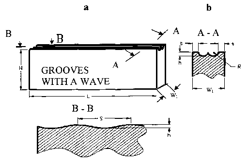
Fig. 6a is a perspective view of a first workpiece having a rectangular
projection at each edge of its lateral faces and a smooth groove between said
rectangular projections along the surface to be mated, mating surface of the
first
worlcpiece having an undulation or wave along its length, and the first
workpiece
being adapted to mate with a second worlcpiece (not shown) having a
2o substantially flat mating surface;
Fig. 6b and be are sectional views of this first workpiece along lines A-A
and B B, respectively:
The interface geometry illustrated in Figs. 6a , 6b and 6c is an example of
the
invention.
AMENDED SHEET
CA 02395323 2002-06-21
WO 01/47691 PCT/US00/34409
11
Fig. 7a is a perspective view of a first workpiece having a rectangular
projection at each edge of its lateral faces and two semi-circular grooves
between
said rectangular projections along the surface to be mated, the mating surface
of
the first workpiece having an undulation or wave along its length, and the
first
workpiece being adapted to mate with a second workpiece (not shown) having a
substantially flat mating surface;
Figs. 7b and 7c are sectional views of the first workpiece shown in Fig.
7a along lines A-A and B-B, respectively.
The interface geometry illustrated in Figs. 7a, 7b and 7c is an example of the
invention.
Fig. 8a is a perspective view of a first workpiece having a rectangular
projection at each edge of its lateral faces and multiple grooves between said
rectangular projections along the surface to be mated with a second workpiece
(not shown) having a substantially flat mating surface;
Fig. 8b is a sectional view of the first workpiece shown in Fig. 8a along
line A-A.
The interface geometry illustrated in Figs. 8a and 8b is an example of the
invention.
Fig. 9 is a sectional view of a prior art complex butt joint with flash traps,
the section schematically illustrating the large amount of flash produced when
flat
surfaces are fractionally welded;
Fig.10 is a sectional view of a complex butt joint of the invention, the
section schematically illustrating how the flash is reduced and a molten pool
is
retained in the region between rectangular edge projections.
CA 02395323 2002-06-21
WO 01/47691 PCT/US00/34409
12
DETAILED DESCRIPTION OF THE INVENTION
The invention provides a frictionally welded, reinforced thermoplastic
article of improved strength by means of restriction to lateral flow of molten
material out of the gap between the workpieces, thereby maintaining a molten
pool of substantial depth from the beginning of melting to the onset of
solidification. Specifically, the restriction to lateral flow of material out
of the
gap between the workpieces is provided by dams (projections) of essentially
rectangular cross-section at each lateral edge of one of the workpieces, while
the
other workpiece has a substantially flat mating surface.
1o The invention also provides a method for preparing friction welded, filled
reinforced thermoplastic articles of improved strength by restricting the
lateral
flow of molten material out of the gap between them, thereby retaining a
molten
pool of substantial depth between them from the beginning of melting to the
onset
of solidification.
15 Techniques of frictional welding and apparatus for conducting frictional
welding are well known in the art. Frictional welders (linear, orbital, spin )
are
commercially available from several multi-national companies (Branson
Ultrasonics, Forward Technologies, Inc., Bielomatik, etc.) in North America,
Europe, Asia, etc. For example, Branson Ultrasonics Corporation, Danbury,
2o Conn., manufactures linear vibration welding machines designated as a Mini-
Vibration Welder II, Ultra HY-Line model VW/8UH, and 90 series Vibration
Welders model VW/6.
Frictional welding may be conducted by placing a first thermoplastic
workpiece and a second thermoplastic workpiece into contact under a
CA 02395323 2002-06-21
WO 01/47691 PCT/US00/34409
13
compressive clamping pressure. The mating surfaces are kept at a predetermined
clamping pressure, for example by positioning them on a platform under
pressure
applied by air or hydraulic cylinders. Motion is then imparted to one surface
with
respect to the other surface to create a frictional rubbing which generates
heat,
melts the surfaces and blends and fuses the thermoplastic materials from the
first
and second workpieces in a "melt down" region. The dimension of the melt down
region is measured by the linear motion of the opposing platforms providing
the
clamping pressure and can be controlled by appropriate machine settings
Clamping pressure is one of the more important parameters. When the
to thermoplastic materials are reinforced with short fibers, such as glass,
carbon,
aramid or other fibers, the manner of blending the materials from the opposing
workpieces becomes very important. Prior to welding, the fibers in the
thermoplastic materials typically are oriented randomly, i.e. have no
preferred
orientation. However, if careful attention is not paid to the conditions of
welding,
15 the relative motion can cause the fibers in the weld region to become
oriented
only within the plane of the weld. This leads to lower strength and mechanical
performance than if the conditions of welding are optimized so as to cause the
fibers to penetrate both into the weld and into the opposing workpiece.
Unfortunately, optimized welding conditions cannot always be achieved.
20 The magnitude of the necessary compressive clamping pressure depends on the
sizes and geometries of the plastic parts and upon the dimensional stability
of the
thermoplastics during previous molding operations. In practice, the workpieces
to be joined are frequently molded with bosses, walls and ribs that cause
differential shrinkage and warpage of the surfaces to be mated. Many
CA 02395323 2002-06-21
WO 01/47691 PCT/US00/34409
14
applications require the welded joint to be hermetically sealed. Under these
circumstances, much higher than optimum clamping pressures must be used to
bring the mating surfaces into uniform contact. This higher than optimum
clamping pressure increases the shear stresses at the interface, accentuates
the
tendency for the fibers to become oriented in the plane of the weld, and
reduces
the tensile strength achieved.
This sensitivity of weld strength to clamping pressure is illustrated by the
data in Table 1 below obtained with planar interface geometries on each
workpiece. The welds of Table 1 were prepared by longitudinal vibration
1o welding in a Branson Ultrasonic Corp., Mini Welder II at a nominal
frequency of
240 Hz, a vibration amplitude of 1.8 mm and a melt down of 1.5 mm. The
material used was a Capron~ nylon 6 from Honeywell International lnc.,
Morristown, New Jersey.
CA 02395323 2002-06-21
WO 01/47691 PCT/US00/34409
Table 1
Influence of Clamping Pressure (MPa) on Weld Tensile Strength at Room
Temperature Capron~ 82336 HS BK-102, nylon 6, 33 wt.% Glass-Fiber
Reinforced
Clamping Pressure,Tensile Strength of
MPa Weld MPa
0.66 73.7
0.86 85.2
1.28 80.3
2.17 77.6
3.5 65
5.6 58.2
6.4 46.8
Without being bound by any particular theory, it is hypothesized that the
effect of higher than optimal clamping pressure has an effect similar to
having a
vi~eld interface thickness which is too low, and which may result in
insufficient
10 space for fiber rotation and hence restrain fibers from crossing the
interface and
penetrating into the opposing workpiece.
To counter this tendency, in this invention the initial, interfacial geometry
was configured to restrict the lateral flow of molten material out of the gap
between the workpieces, thereby maintaining a molten pool of substantial depth
15 from the beginning of melting to the onset of solidification (Compare Figs.
9 and
10).
CA 02395323 2002-06-21
WO 01/47691 PCT/US00/34409
16
According to the invention, the two thermoplastic workpieces to be
welded are composed of any compatible thermoplastic polymeric material.
Suitable thermoplastic polymers nonexclusively include polyamides, polyesters,
polycarbonates, polysulfones, polyimides, polyurethanes, polyethers,
polyolefins,
vinyl polymers, and mixtures thereof. Polyamides such as nylon 6 and nylon 66
for example Capron~ 82336 HS nylon 6 and Capron~ 52336 HS nylon 66 from
Honeywell International of Morrnstown, N.J. and polyesters such as Petra~ 130
polyethylene terepthalate available from Honeywell International are most
preferred. Dissimilar thermoplastic materials may be used provided they blend
1 o compatibly. At least one and preferably both of the thermoplastic
materials are
fiber reinforced. Suitable reinforcing fibers non-exclusively include material
which do not soften, i.e. lose their rigidity, at'temperatures typically used
for
injection molding, such as temperatures up to about 400°C. Preferably
the fiber
reinforcement comprises such a material as glass, carbon, silicon, metals;
1 s minerals, polymeric fibers and mixtures thereof. Glass fiber reinforcement
is
most preferred. In the preferred embodiment, the fiber is rigid and has a
diameter
of from about 8 to about 12 micrometers, preferably from about 9 to about 11
micrometers and most preferably about 10 micrometers. The preferred fiber
length is from about 120 to about 300 micrometers, more preferably from about
2o 130 to 250 micrometers and most preferably from about 140 to about 200
micrometers. In the preferred embodiment the fibers comprise from about 6 to
about 63 weight percent (wt.%) of the thermoplastic composition and more
preferably from about 10 to about 40 wt.% and most preferably from about 14 to
25 wt.%.
17-12-2001 U S003440~
CA 02395323 2002-06-21
17
Referring to Figures 4a and 4b there are depicted workpieces to be joined
in accordance with the invention. First workpiece 10 has an initial mating
surface
14 and substantially rectangular projections 18 at each lateral edge thereof.
Second workpiece 12 has a substantially flat mating surface 16. First
workpiece
and second workpiece 12 are joined by placing their respective mating
surfaces in juxtaposed relationship, pressing the workpieces together under
compressive clamping pressure, moving the first workpiece (10) relative to the
second workpiece (12) in a plane parallel to their interface sufficient to
frictionally heat the interface and melt the interfacial surfaces of the first
and
1 0 second workpieces to create a melt down region 20, and allowing the melt
down
region to solidify.
According to the invention, the thickness of the projections 18 of the first
workpiece 10 are proportioned in relationship to the thickness of the
workpiece.
The thickness of each projection 18 (dimension t in Figs. 4 -7; dimension t1
in
is Fig. 8) is typically between about 5% and about 3s% of the thickness of the
workpiece 10 (dimension Wl in Figs. 4 - 8).
t / Wl ~-_ 0.05 to 0.35 ; t1 /W1 ~-_ 0.05 to 0.35
Preferably, the thickness of each projection 18 will be between about 10%
to about 20% of the thickness of the first workpiece 10.
2o t/Wl=0.10to0.20; tl/Wl~.lOto0.20
The height of each projection 18 (h in Figs. 4 - 8) relative to the lowest
point on the initial mating surface 14 should be in proportion to the desired
melt
down (MD). The height of each projection is typically at least about 25% of
the
melt down and preferably at least about 33% of the melt down.
AMENDED SHEET
17-12-2001 US003440!
CA 02395323 2002-06-21
178
h/MD 2 0.25 ; Preferably, h/MD z 0.33
Alternatively, the geometry of the initial mating surface 14 of the first
workpiece 10 can be defined in terms of the volume of the largest melt pool
that
can be contained relative to the maximum volume of melt produced by welding.
The volume of the largest melt pool that can be contained between the
rectangular
edge projections 18 is equal to the length of the worlq'iece 10 times the
cross-
sectional area of the region defined by the horizontal line between the upper
edges of the rectangular projections 18 and the boundaries of the space
defined
by the rectangular projections 18 and the material surface between them. Call
this
1o cross-sectional area A. The maximum volume of melt produced by welding is
the
length of the
AMENDED SHEET
17-12-2001 US003440'
CA 02395323 2002-06-21
I8
workpiece times the alt down (MD) times the thiclaiess of the workpiece (W1).
Therefore, the volume of the largest melt pool that can be contained between
the
rectangular projections 18 in relation to the largest volume of melt produced
by
welding is AI(MD x Wl). According to the invention this proportion is at least
about 0.15 (15%) and preferably is at least about 0.20 (20%).
AJ(MD x Wl) z 0.15 ; Preferably, A/(MD a Wl) Z 0.20
It is also contemplated that in addition to the essentially rectangular
projections 18 at each lateral edge, the first workpiece 10 may have an
undulation
or wave along its length. The amplitude of this undulation (peak to- trough)
is
1o from about 20% to about 800% of the melt down.
The second worlcpiece 12 will have a substantially flat mating surface 16.
In the context of this invention, a substantially flat mating surface is one
that
maintains restriction of melt flow from between the mating surfaces of the two
is worlcpieces. The second worlcpiece 12 may have some convexity or concavity
so
long as the departure from planarity is less than about 1 mm, preferably less
than
about 0.5 mm in the region where it will abut the rectangular projections 18
of the
first worlcpiece 10.
The following non-linuting examples serve to illustrate the invention. it
2o will be recognized thax variations in elements and proportions may be made
by
those skilled in the art without departing from the scope of the present
invention.
AMENDED SHEET
CA 02395323 2002-06-21
WO 01/47691 PCT/US00/34409
19
EXAMPLES AND COMPARATIVE EXAMPLES
A series of linear vibration welded articles were prepared from injection
molded plaques of different fiber reinforced thermoplastic materials, and of
different initial interface geometries, all using the following constant
conditions:
~ Type of Joint: Butt Joint with same thermoplastic
Welder / Welding Machine: Branson Ultrasonic s Corp., Model Mini Welder
B
~ Initial Dimensions of Molded Plaques:
- First Workpiece: Width (W,) x Length (L) x Thickness(T): 15.24 cm x
l0 6.35 cm x 0.396 cm
- Second Workpiece: Width (W2) x Length (L) x Thickness(T): 15.24 cm
x 6.35 cm x 0.624 cm
Dimensions of Welded Plaques: (W x L): 15.24 cm x 12.7 cm
Initial Interface Design of Workpiece 1: See Table 2
Initial Interface Design of Workpiece 2: Flat
Welding Conditions
Vibration Frequency: 240 Hz (nominal)
Vibration Amplitude: 1.77 mm
Weld clamping pressure: 3 MPa
2o Vibration Direction: Width of plaques (longitudinal)
Welding Environment: Std. Lab. Atmosph., 23°C, SO ~5% R.H.
Melt-down: 1.5 mm
Thermoplastic Materials:
Capron~ 82336 HS nylon 6, 33 wt.% glass fiber
CA 02395323 2002-06-21
WO 01/47691 PCT/US00/34409
Capron~ 82676, nylon 6, 15 wt.% glass fiber + 25 wt.% mineral fillers
Capron~ RX-1104, nylon 6, 33 wt.% glass fiber
Zytel~ 70633 HS 1 L (DuPont), nylon 66, 33 wt.% glass fiber
5 The welded plaques were cut into 1.27 cm wide strips (rectangular
specimens) and the tensile strengths of the welded joints were determined by
the
ISO 527 / ASTM D 638 testing method for plastics at a strain rate of 5 mm/min,
at room temperature 23°C.
The tensile strengths determined for the comparative examples and the examples
10 of the invention as shown in the Figures are presented in Table 2 below.
Tensile Strength of Welded Joints vs. Interface Design
Tensile
Strength
of Welded
Joints,
M Pa
Design
of Workpiece
1
ComparativeComparativeComparativeExampleExample
2
Example Example Example 1
1 2 3
"Flat" "Teeth" "Bump" "Smooth"Grooves"
Groove"
Fig.1 Fig.2 Fig.3 Fig.4 Fig.S
t~~ - - - 0.19 0.13
h/MD - - - 0.33 0.42
A/ (W, x MD) - - - 0.24 0.21
Material
Capron~ 8233669.03 70.09 67.64 76.08 74.95
HS
Capron ~ 8267672.63 73.66 73.18 77.04 79.07
HS
Capron~ RX-110466.91 69.76 59.06 71.99 72.78
Zytel~ 73G30HS71.90 75.77 72.57 76.56 75.96
1 L
AVtKAC~t 70.11 72.32 68.11 75.42 75.69
RelativeTensile 1.00 1.03 0.97 1.08 1.08
Strength
An analysis of variance of the tensile data shows a highly significant
difference
15 between the tensile strengths of the examples of the invention and the
comparative
17-12-2001 US003440~
CA 02395323 2002-06-21
21
examples. This statistically significant diiTerence is also highly
advantageous
from a technological point of view.
The data illustrate the benefits of configuring the initial interface design
to
restrict the lateral flow of melt out of the gap between the workpieces ( i 0,
12)
thmugh the use of darns (projections 18) of essentially rectangular cross-
section
at each lateral edge of one of the workpieces 10 while the other workpiece 12
has
a substantially flat mating surface 16. This can be seen in several ways.
The examples of the invention (Examples 1 and 2) had superior strength
to Comparative Example 1 where the initial mating surfaces were flat on both
l0 workpieces. The examples of the invention had superior strength to
Comparative
Example 2, which had 'teeth"-1'ke projections at each edge of the initial
mating
surfaces. The greatest difference of all was between the examples of the
invention
and Comparative Example 3. In Comparative Example 3, the first workpiece had
a convex "bump" which tended to accelerate melt out of the gap between the
1 S workpieces.
Example 3
Welded plaques are formed as in Examples 1 and 2 above using the
workpiece design of Fig. 6. The tensile strengths of the welded joints are
2o improved relative to those of Comparative Example 1.
Example 4
Welded plaques are formed as in Examples 1 and 2 above using the
workpiece design of Fig. 7. The tensile strengths of the welded joints are
improved relative to those of Comparaxive Example 1.
AMENDED SHEET
CA 02395323 2002-06-21
WO 01/47691 PCT/US00/34409
22
Having thus described the invention in rather full detail, it will be
understood that such detail need not be strictly adhered to but that further
changes
and modifications may suggest themselves to one skilled in the art, all
falling
within the scope of the invention as defined by the subjoined claims.