Language selection

Search

Patent 2395634 Summary

Third-party information liability

Some of the information on this Web page has been provided by external sources. The Government of Canada is not responsible for the accuracy, reliability or currency of the information supplied by external sources. Users wishing to rely upon this information should consult directly with the source of the information. Content provided by external sources is not subject to official languages, privacy and accessibility requirements.

Claims and Abstract availability

Any discrepancies in the text and image of the Claims and Abstract are due to differing posting times. Text of the Claims and Abstract are posted:

  • At the time the application is open to public inspection;
  • At the time of issue of the patent (grant).
(12) Patent Application: (11) CA 2395634
(54) English Title: DEVICE FOR THE CONTINUOUS CASTING OF METALS, ESPECIALLY STEEL
(54) French Title: DISPOSITIF DE COULEE CONTINUE DE METAUX, EN PARTICULIER D'ACIER
Status: Deemed Abandoned and Beyond the Period of Reinstatement - Pending Response to Notice of Disregarded Communication
Bibliographic Data
(51) International Patent Classification (IPC):
  • B22D 11/16 (2006.01)
  • B22D 11/053 (2006.01)
(72) Inventors :
  • FISCHER, LOTHAR (Germany)
  • ZAJBER, ADOLF (Germany)
  • FEST, THOMAS (Germany)
  • SCHWENECKE, SIEGBERT (Germany)
(73) Owners :
  • SMS DEMAG AKTIENGESELLSCHAFT
(71) Applicants :
  • SMS DEMAG AKTIENGESELLSCHAFT (Germany)
(74) Agent: RICHES, MCKENZIE & HERBERT LLP
(74) Associate agent:
(45) Issued:
(86) PCT Filing Date: 2001-05-05
(87) Open to Public Inspection: 2001-11-15
Availability of licence: N/A
Dedicated to the Public: N/A
(25) Language of filing: English

Patent Cooperation Treaty (PCT): Yes
(86) PCT Filing Number: PCT/EP2001/005117
(87) International Publication Number: WO 2001085370
(85) National Entry: 2002-06-25

(30) Application Priority Data:
Application No. Country/Territory Date
100 22 598.5 (Germany) 2000-05-10

Abstracts

English Abstract


The invention relates to a device for the continuous casting of metals,
especially steel, by means of a continuous casting mould (1) which is mounted
in an oscillating frame (3). Said oscillating frame can be driven so that it
oscillates in the direction of casting (2), the course of the oscillation
movement and/or the frequency being adjustable. The oscillating frame (3) is
mounted with spring assemblies (4a, 4b; 5a, 5b) arranged symmetrically on both
sides of the strand, for guiding and weight compensation. The device is used
on a continuous casting mould (1) with a shaped casting cross-section (1a),
which is mounted in the oscillating frame (3). The leaf-spring-mounted
oscillating frame (3) can be operated with the continuous casting mould (1) in
a resonance oscillation method in order to give the preliminary section a
better surface.


French Abstract

La présente invention concerne un dispositif de coulée continue de métaux, en particulier d'acier, au moyen d'une coquille de coulée continue (1) qui est disposée dans un bâti oscillant (3) pouvant être entraîné en oscillation dans une direction de coulée (2). Selon l'invention, la course du mouvement d'oscillation et/ou la fréquence sont réglables et le bâti oscillant (3) est disposé de manière à permettre le guidage et la compensation de poids, au moyen d'ensembles de ressorts (4a, 4b; 5a, 5b) disposés symétriquement aux deux extrémités de la veine de coulée. Ledit dispositif de coulée est utilisé sur une coquille de coulée continue (1) à section de coulée profilée (1a), disposée dans le bâti oscillant (3), le bâti oscillant (3) monté sur ressorts à lames, pouvant être entraîné avec la coquille de coulée continue (1) dans le processus d'oscillation de résonance, afin de donner au profilé une surface de meilleure qualité.

Claims

Note: Claims are shown in the official language in which they were submitted.

CLAIM (S)
1. Machinery for the continuous casting of metals,
especially steel, by means of a continuous casting mold, which is
mounted in an oscillating frame that can be reciprocated in the
direction of casting, such that the amplitude and/or the
frequency of the oscillation can be adjusted, and the oscillating
frame is mounted with spring assemblies, which are symmetrically
arranged on both sides of the strand, for guidance and weight
compensation, characterized by the use of a continuous casting
mold (1) with a shaped casting cross section (1a), which is
mounted in the oscillating frame (3), such that the oscillating
frame (3), which is mounted on leaf springs, and the continuous
casting mold (1) can be operated by the resonance oscillation
method.
2. Machinery in accordance with Claim 1, characterized by
the fact that the continuous casting mold (1) with a shaped
casting cross section (1a) has a casting cross section with a
dog-bone shape.
3. Machinery in accordance with Claim 1 or 2, characterized
by the fact that the oscillatory motion can be varied by the
drive (6) with respect to the oscillation amplitude and/or
oscillation frequency and/or oscillation curve.
4. Machinery in accordance with any of Claims 1 to 3,
characterized by the fact that the oscillatory motion can be
transmitted to the oscillating frame (3) by a hydraulic, electric
or electromechanical drive (6).
9

5. Machinery in accordance with any of Claims 1 to 4,
characterized by the fact that the frictional force can be
influenced by the amplitude of the oscillation or by the type of
oscillatory motion of the oscillating frame (3).
6. Machinery in accordance with any of Claims 1 to 5,
characterized by the fact that the amplitude of the oscillatory
motion of the oscillating frame (3) can be adjusted to about 0.3-
6 mm.
7. Machinery in accordance with any of Claims 1 to 6,
characterized by the fact that in a base frame (7), leaf spring
assemblies (4a, 4b; 5a, 5b), which run in pairs on both sides at
an acute angle to each other, are flexibly mounted at both ends,
and that the oscillating frame (3) that supports the continuous
casting mold (1) is mounted by means of supporting brackets (8),
which are secured to the leaf spring assemblies (4a, 4b; 5a, 5b)
between the ends (3a; 3b) and which join the leaf spring
assemblies and the oscillating frame (3).
8. Machinery in accordance with Claim 7, characterized by
the fact that the upper pair of leaf spring assemblies (5a, 5b)
is horizontally mounted in the base frame (7), which itself is
horizontal or inclined.
9. Machinery in accordance with any of Claims 1 to 8,
characterized by the fact that a hydraulic drive (9) for the
oscillating frame (3) is provided, to which a measuring device is
connected for determining the pressures in the working cylinder
(9a), which can then be used to compute the frictional force

between the casting strand and the continuous casting mold (1).
10. Machinery in accordance with any of Claims 1 to 9,
characterized by the fact that an automatic casting flux feeder
is provided.
11

Description

Note: Descriptions are shown in the official language in which they were submitted.


TRANSLATION:
4V0 01/85,370 A1 PCT/EPO1/05,117
MACHINERY FOR THE CONTINUOUS CASTING
OF METALS, ESPECIALLY STEEL
The invention concerns machinery for the continuous casting
of metals, especially steel, by means of a continuous casting
mold, which is mounted in an oscillating frame that can be
reciprocated in the direction of casting. The amplitude and/or
the frequency of the oscillation can be adjusted. The
oscillating frame is mounted with spring assemblies, which axe
symmetrically arranged on both sides of the strand, for guidance
and weight compensation.
The continuous casting of slabs, e.g.. with a casting cross
section of 210/250 x 1,000-2,050 mm, on a so-called resonance
mold is well known (EP 0,468,607 81). The advantages of this
type of resonance mold are basically a reduction in weight of-the
oscillating components and improvement of the dynamics, so that
the features of a servohydraulic drive can be utilized. The
liquid-cooled continuous casting mold used for this purpose in an
oscillation arrangement has spring elements, which have
significantly lower stiffness in the casting direction than the
transverse directions, are uniformly distributed, are mounted on
one side, and extend transversely to the direction of casting.
The opposite ends of the spring elements are mounted on a base
plate, and the base plate is fastened to a stationary base frame.
CA 02395634 2002-06-25

The reciprocating drive acts on the supporting plate. Leaf
springs of this design are also known, such that the nonrigid
leaf springs are mounted in parallel position both with respect
to one another and with respect to the leaf springs located on
the opposite narrow side of the mold (EP 0,953,391 A1).
The casting of shaped strands (except for simple polygonal
shapes) is technologically demanding, because the frictional
force and the casting flux criteria for individual varieties of
steel are largely undetermined. Therefore, poor strand surfaces
are repeatedly obtained due to high frictional forces. In the
extreme case, sticking-type breakouts destroy the result of the
entire operation and cause severe economic loss. Casting cross
sections where the longitudinal and narrow sides of the mold are
nonuniform are affected to an even greater extent.
The goal of the invention is to improve the casting of cross
sections that are complicated compared to simple rectangular slab
cross sections.
In accordance with the invention, this goal is achieved with
machinery, of the type described at the beginning, for the
continuous casting of metals, especially steel, by the use of a
continuous casting mold with a shaped cross section, which is
mounted in the oscillating frame, such that the oscillating
frame, which is mounted on leaf springs, and the continuous
casting mold can be operated by the resonance oscillation method.
The use of leaf springs ensures deflection that is free of
backlash and wear with guiding precision that is many times
2
CA 02395634 2002-06-25

better than that of previous oscillation equipment and thus
significantly reduced strand friction. A sinusoidal oscillation
or a nonsinusoidal oscillation with high frequencies and small
amplitudes contributes to this. Moreover, this so-called
resonance oscillation is promoted by a reduction in weight of the
oscillating frame components. It is now possible to produce high
surface quality even on shaped casting strands, which is
associated with improvement of the cast structure near the edges.
In addition, the crack sensitivity can also be reduced.
The advantages of the invention can be illustrated by a
selected design example in which the continuous casting mold
produces a casting cross section that is shaped like a dog bone.
Due to the characteristics of the so-called resonance mold
that have been described, the strand surface can be improved
basically by variation of the oscillatory motion by the drive
with respect to the oscillation amplitude and/or the oscillation
frequency and/or the oscillation curve. The reduction of
friction can be computed with computer models, and the values
obtained in this way can be input to control the particular
drive.
One design provides for influencing the frictional force by
the amplitude of the oscillatory motion of the oscillating frame.
The continuous casting mold operated by the resonance method can
be given a low friction value by adjusting the amplitude of the
oscillatory motion of the oscillating frame to about 0.3-6 man.
In accordance with one improvement, the continuous casting
3
CA 02395634 2002-06-25

mold for the resonance oscillation method is mounted in such a
way that leaf spring assemblies that run in pairs on both sides
at an acute angle to each other are flexibly mounted at both
ends, and that the oscillating frame that supports the continuous
casting mold is mounted by means of supporting brackets, which
are secured at the midpoint of the leaf spring assemblies and
which join the leaf spring assemblies and the oscillating frame.
This mounting produces the desired precise guidance using
structural members of the lowest possible weight.
In general, the invention provides that the upper pair of
leaf spring assemblies is horizontally mounted in the base frame,
which itself is horizontal or inclined.
In accordance with additional features of the invention, the
surface of the solidifying strand being cast can be monitored by
providing the oscillating frame with a hydraulic drive to which a
measuring device is connected for determining the pressures in
the working cylinder, which can then be used to compute the
frictional force between the strand being cast and the continuous
casting mold.
Finally, another measure for homogeneous surface forming
consists in the use of an automatic casting flux feeder. This
assures more uniform distribution of the casting flux and further
reduction of friction. The invention will now be explained in
greater detail with reference to the embodiment shown in the
drawings.
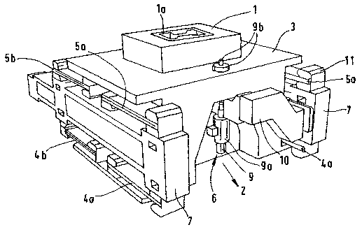
Figure 1 shows a perspective view of a resonance continuous
4
CA 02395634 2002-06-25

casting mold, and
Figure 2 shows a section through a resonance continuous
casting mold.
Figure 1 shows machinery for the continuous casting of
metals, especially steel, by means of a continuous casting mold
1, which is mounted in an oscillating frame 3 that can be
reciprocated in the direction of casting 2. The amplitude and/or
the frequency of the oscillation can be adjusted. The
oscillating frame 3 is mounted with spring assemblies 4a, 4b; 5a,
5b, which are symmetrically arranged on both sides of the strand,
for guidance and weight compensation. The continuous casting
mold 1 has a shaped casting cross section 1a, and the oscillating
frame 3, which is mounted on the leaf springs, and the continuous
casting mold 1 can be operated by the resonance oscillation
method. A dog-bone mold is shown as a good example of a shaped
casting cross section 1a, with which the starting material for I-
beam sections is cast. A homogeneous surface without serious
defects is produced by varying the oscillatory motion by means of
the drive 6 with respect to the oscillation amplitude and/or the
oscillation frequency and/or the oscillation curve. This
oscillatory motion can be transmitted to the oscillating frame 3
by a hydraulic, electric, or electromechanical drive 6. In this
regard, the friction is to be influenced by means of the
amplitude of the oscillatory motion of the oscillating frame,
i.e., it is to be kept as small as possible. The frictional
force and the surface quality can be influenced especially by
CA 02395634 2002-06-25

relatively low amplitudes of the oscillatory motions, e.g., by
adjusting the amplitude of the oscillatory motion of the
oscillating frame to about 0.3-6 mm. The drive 6 acts on the
oscillating frame at the point of application 6a indicated on the
left side of Figure 2.
The design of the mold oscillation equipment is shown in
greater detail in Figure 2. In a base frame 7, leaf spring
assemblies run in pairs on both sides at an acute angle to each
other (assemblies 4a and 4b below and 5a and 5b above).
The drive 6 for the oscillatory motions may consist, as
shown in Figure 1, of a hydraulic drive 9 with a working cylinder
9a, whose driving rod 9b passes through the oscillating frame and
is bolted into it. The oscillating frame 3 is supported on a
crossrail 10 for the drive 6. Each of the leaf spring assemblies
4a, 4b and 5a, 5b.is clamped at its end by means of a spring
clamp 11, as is clearly shown in Figure 2.
As Figure 2 shows, a base frame 7 supports the oscillating
frame 3, which has a lower standard that supports a supporting
bracket 8. The oscillating frame 3 is joined to the base frame 7
by means of a fastening plate 12 and supporting bracket bolted
joints 13 (each consisting of a bolt, a nut and a washer), which
also clamp the leaf spring assemblies 4a, 4b (5a, 5b). The
movement of the oscillating frame 3 is limited below by a safety
stop 14.
Each of the leaf spring assemblies 4a, 4b (5a, 5b on the
other side) is mounted on the base frame 7 in the same way by a
6
CA 02395634 2002-06-25

lower fastening plate 15 and bolted joints 16. The placement of
each of the leaf spring assemblies 4a, 4b is spatially terminated
by a guard plate 17. A centering rod 18 and lateral connecting
bolts 19 are also present.
In the upper part of the base frame 7, the leaf spring
assemblies 5a, 5b are mounted by upper fastening plates 20 and
upper bolted joints 21. In an analogous design, the upper
supporting bracket 8 is provided with upper supporting bracket
bolted joints 22 and an upper stop 23. For the upper leaf spring
assemblies 5a and 5b, a base frame part 24 is likewise provided
for bounding the leaf spring assembly 5b. Joining elements 25
are also shown.
7
CA 02395634 2002-06-25

CA 02395634 2002-06-25
List of Reference Numbers
1 continuous casting mold
1a shaped casting cross section
2 casting direction
3 oscillating frame
3-a end
3b end
4a leaf spring assembly
4b leaf spring assembly
5a leaf spring assembly
5b leaf spring assembly
6 drive
6a point of application for the drive
7 base frame
8 supporting bracket
9 hydraulic drive
9a working cylinder
9b driving rod with bolted joint
crossrail for the drive
11 spring clamp
12 lower fastening plate
13 lower supporting bracket bolted joint
14 safety stop
lower fastening plate
16 bolted joint
17 guard plate
18 centering rod
19 lateral connecting bolt
upper fastening plate
21 upper bolted joints
22 upper supporting bracket bolted joint
23 upper stop
24 base frame part
joining elements
8

Representative Drawing
A single figure which represents the drawing illustrating the invention.
Administrative Status

2024-08-01:As part of the Next Generation Patents (NGP) transition, the Canadian Patents Database (CPD) now contains a more detailed Event History, which replicates the Event Log of our new back-office solution.

Please note that "Inactive:" events refers to events no longer in use in our new back-office solution.

For a clearer understanding of the status of the application/patent presented on this page, the site Disclaimer , as well as the definitions for Patent , Event History , Maintenance Fee  and Payment History  should be consulted.

Event History

Description Date
Inactive: IPC from MCD 2006-03-12
Application Not Reinstated by Deadline 2004-05-05
Time Limit for Reversal Expired 2004-05-05
Appointment of Agent Requirements Determined Compliant 2004-04-21
Inactive: Office letter 2004-04-21
Revocation of Agent Requirements Determined Compliant 2004-04-21
Appointment of Agent Request 2004-04-13
Revocation of Agent Request 2004-04-13
Deemed Abandoned - Failure to Respond to Maintenance Fee Notice 2003-05-05
Letter Sent 2002-12-12
Inactive: Courtesy letter - Evidence 2002-11-05
Inactive: Cover page published 2002-11-04
Inactive: Notice - National entry - No RFE 2002-10-29
Inactive: Single transfer 2002-10-23
Application Received - PCT 2002-09-10
National Entry Requirements Determined Compliant 2002-06-25
Application Published (Open to Public Inspection) 2001-11-15

Abandonment History

Abandonment Date Reason Reinstatement Date
2003-05-05

Fee History

Fee Type Anniversary Year Due Date Paid Date
Basic national fee - standard 2002-06-25
Registration of a document 2002-10-23
Owners on Record

Note: Records showing the ownership history in alphabetical order.

Current Owners on Record
SMS DEMAG AKTIENGESELLSCHAFT
Past Owners on Record
ADOLF ZAJBER
LOTHAR FISCHER
SIEGBERT SCHWENECKE
THOMAS FEST
Past Owners that do not appear in the "Owners on Record" listing will appear in other documentation within the application.
Documents

To view selected files, please enter reCAPTCHA code :


To view images, click a link in the Document Description column. To download the documents, select one or more checkboxes in the first column and then click the "Download Selected in PDF format (Zip Archive)" or the "Download Selected as Single PDF" button.

List of published and non-published patent-specific documents on the CPD .

If you have any difficulty accessing content, you can call the Client Service Centre at 1-866-997-1936 or send them an e-mail at CIPO Client Service Centre.


Document
Description 
Date
(yyyy-mm-dd) 
Number of pages   Size of Image (KB) 
Representative drawing 2002-06-25 1 21
Abstract 2002-06-25 1 25
Claims 2002-06-25 3 91
Description 2002-06-25 8 309
Drawings 2002-06-25 2 70
Cover Page 2002-11-04 1 54
Notice of National Entry 2002-10-29 1 192
Reminder of maintenance fee due 2003-01-07 1 106
Courtesy - Certificate of registration (related document(s)) 2002-12-12 1 106
Courtesy - Abandonment Letter (Maintenance Fee) 2003-06-02 1 175
PCT 2002-06-25 5 207
Correspondence 2002-10-29 1 25
PCT 2002-06-26 2 87
Correspondence 2004-04-13 5 159
Correspondence 2004-04-21 1 13
Correspondence 2004-04-21 1 20