Note: Descriptions are shown in the official language in which they were submitted.
CA 02395690 2006-05-02
TECHNIQUES FOR ADAPTING A SMALL FORM FACTOR INK-JET
CARTRIDGE FOR USE IN A CARRIAGE SIZED FOR A LARGE FORM
FACTOR CARTRIDGE
CROSS REFERENCE TO RELATED APPLICATIONS
This application is related to the following U.S. patents each filed
concurrently
on January 5, 2000: U.S. Patent No. 6,332,676 entitled "Vent For An Ink-Jet
Print
Cartridge"; U.S. Patent No. 6,227,663 entitled "Ink-Jet Print Cartridge Having
A Low
Profile"; U.S. Patent No. 6,499,826 entitled "Horizontally Loadable Carriage
For An
Ink-Jet Printer"; U.S. Patent No. 6,296,345 entitled "Method And Apparatus For
Horizontally Loading And Unloading An Ink-Jet Print Cartridge From A
Carriage";
U.S. Patent No. 6,290,348 entitled "Techniques For Providing Ink-Jet
Cartridges With
A Universal Body Structure"; U.S. Patent No. 6,540,320 entitled "Printer With
A
Two Roller, Two Motor Paper Delivery System"; U.S. Patent No. 6,293,718
entitled
"Low Height Inkjet Service Station"; U.S. Patent No. 6,290,346 entitled "New
Method Of Propelling An Inkjet Printer Carriage"; and U.S. Patent No.
6,471,426
entitled "Multiple Bit Matrix Configuration For Key-Latched Printheads".
BACKGROUND OF THE INVENTION
This invention relates to ink-jet pens and printers, and more particularly to
techniques for adapting a small ink-jet pen for operation in a printer
carriage
constructed to receive an ink-jet pen of a larger size.
Ink-jet printers are in widespread use today for printing functions in
personal
computers, graphics plotters, facsimile machines and other applications. Such
printers
typically include replaceable or semipermanent print cartridges which hold a
supply
of ink and carry the ink-jet printhead. The cartridge typically is secured
into a printer
carriage which supports one or a plurality of cartridges above the print
medium, and
traverses the medium in a direction transverse to the direction of medium
travel
through the printer. Electrical connections are made to the printhead by
flexible
wiring circuits attached to the outside of the cartridge. The carriage
receptacle has a
corresponding electrical circuit with exposed contact pads which contact
cartridge
interconnect pads when the cartridge is mounted in the carriage. Each
printhead
CA 02395690 2006-05-02
2
includes a number of tiny nozzles defined in a substrate and nozzle plate
structure
which are selectively fired by electrical signals applied to the interconnect
pads to
eject droplets of ink in a controlled fashion onto the print medium. The
cartridge may
be connectable to auxiliary supplies of ink for replenishing the internal
supply held in
the cartridge.
In order to achieve accurate printing quality, each removable cartridge
includes datum surfaces which engage against corresponding carriage surfaces
to
precisely locate the cartridge when inserted into the carriage. In this
manner, when a
cartridge ink supply is exhausted, the cartridge may be replaced with a fresh
cartridge,
and the printhead of the new cartridge will be precisely located relative to
the
carriage. The printer carriage receptacle and the cartridge are therefore
designed
together, so that the cartridge fits accurately within the carriage
receptacle, the
respective circuit pads and datum surfaces match up, and the cartridge can be
removed and replaced with a fresh cartridge as needed.
Ink-jet cartridges can be of varying shapes and sizes. Heretofore, a cartridge
of
one size could not be used in a printer carriage designed to receive a
cartridge of a
different size, since the datums and the electrical contacts on the cartridge
and the
carriage would not match up.
It would therefore be an advantage to provide a technique to allow a cartridge
of one size or configuration to be used in a printer with a carriage
receptacle designed
for use with a cartridge of a different size or configuration.
SUMMARY OF THE INVENTION
Accordingly, in one aspect of the present invention there is provided an
adapter kit for inkjet cartridges, comprising, in combination:
an inkjet cartridge including a cartridge housing, a printhead mounted on the
housing, a plurality of datum surfaces on said housing for registering a
position of the
cartridge housing in a fixed, repeatable position in a first carriage
structure, and a
cartridge set of electrical contacts mounted to the cartridge housing and
electrically
coupled to the printhead, said cartridge set of electrical contacts positioned
on the
housing for electrical contact with a corresponding first carriage set of
electrical
contacts when the cartridge is mounted in the first carriage structure; and
CA 02395690 2006-05-02
3
an adapter structure for attachment to the cartridge housing to provide an
assembly of said adapter structure and said cartridge, said assembly adapted
for
mounting in a second carriage structure configured to receive an inkjet
cartridge of a
different size in a fixed, repeatable position, said second carriage structure
having a
second carriage set of electrical contacts, and wherein contact is made
between said
set of electrical contacts and said second carriage set of contacts when the
cartridge is
in said fixed, repeatable position in said second carriage structure.
According to another aspect of the present invention there is provided an ink
delivery system comprising:
a short form factor ink jet cartridge having a supply of ink to facilitate the
depositing of ink on an ink receiving medium; and
an adapter mounted to said short form factor cartridge to permit it to be
removably mounted within a cartridge stall dimensioned to receive a tall form
factor
cartridge.
According to yet another aspect of the present invention there is provided a
method for mounting a short form factor ink jet cartridge into a receptacle
stall sized
for a tall form ink jet cartridge, comprising:
providing the short form factor ink jet cartridge having a supply of ink for
facilitating the depositing of ink on an ink receiving medium; and
mounting an adapter to said short form factor cartridge to provide a cartridge-
adapter assembly for removably mounting within the cartridge stall dimensioned
to
receive a tall form factor cartridge; and
mounting the assembly in the cartridge stall.
According to still yet another aspect of the present invention there is
provided
a method of using a short form factor ink jet cartridge having a supply of
ink,
comprising:
attaching an adapter to the short form factor ink jet cartridge to form a tall
form factor cartridge assembly;
removably mounting said tall factor cartridge assembly within a cartridge
stall
dimensioned to receive a tall form factor ink jet cartridge.
CA 02395690 2006-05-02
4
BRIEF DESCRIPTION OF THE DRAWINGS
These and other features and advantages of the present invention will become
more apparent from the following detailed description of an exemplary
embodiment
thereof, as illustrated in the accompanying drawings, in which:
FIG. 1 is an isometric view of a small form factor inkjet cartridge with which
the subject invention can be employed.
FIG. 2 is a bottom view of the cartridge of FIG. 1.
FIG. 3 is a simplified side view illustrating the latching of the cartridge of
FIG. 1 in a carriage receptacle.
FIG. 4 is an isometric view of the cartridge of FIG. 1 mounted in a carriage
receptacle.
FIG. 5 is an isometric view of an adapter structure in accordance with the
invention.
FIG. 6 is a top view of the adapter structure of FIG. 5.
FIG. 7 is a front view of an assembly of the cartridge of FIG. 1 and the
adapter
structure of FIG. 5.
FIG. 8 is an isometric view of the assembly of FIG. 7.
FIG. 9 is a front view illustrating a size comparison of the cartridge of FIG.
1,
the assembly of FIG. 7 and a large form factor ink-jet cartridge.
FIG. 10 is a bottom side isometric view of a small form factor cartridge
assembly in accordance with the invention and a large form factor cartridge.
CA 02395690 2002-06-17
WO 01/49496 PCT/US00/24440
FIG. 11 is an isometric view of a carriage sized for mounting two large form
factor cartridges, and having mounted therein one large form factor cartridge
and one
small form factor cartridge with an adapter in accordance with the invention.
FIG. 12 is an isometric view of an alternative embodiment of an adapter
structure
5 employing a pressure connector to attach to the cartridge of FIG. 1.
FIG. 13 is an isometric view of the assembly of the cartridge of FIG. 1 and
the adapter
structure of FIG. 12.
DETAILED DESCRIPTION OF THE PREFERRED EMBODIMENT
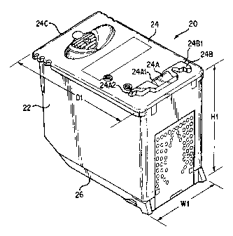
A small form factor inkjet cartridge 20 is shown in FIGS. 1-4, and is
characterized by a relatively small height dimension H1, in this exemplary
embodiment
on the order of 45 mm. This is compared to a typical height dimension of 72 mm
for the
HP 51629A (black ink), 51629G (black ink), 51649A (tri-color) and 51649G (tri-
color)
cartridges marketed by Hewlett-Packard Company. The width dimension W 1 and
depth
dimension D 1 are the same as for these already marketed cartridges; typical
values for
W1 and Dl are 30.9 mm and 48.3 mm, respectively. The small form factor
cartridge 20
has utility for a variety of applications, including by way of example low
profile printing
devices and entertainment center printers.
The cartridge 20 includes a cartridge housing 22, typically fabricated of a
plastic
material, to which a top end cap or lid 24 is attached, e.g. by adhesive or
ultrasonic
bonding techniques. A bottom end cap or nose piece 26 is attached to the lower
end of
the housing, and supports a printhead 28 (FIG. 2). The housing 22 has formed
therein at
least one ink reservoir chamber, filled with a foam material in this example,
for holding a
supply of ink to supply the printhead during printing operations for
delivering ink
droplets onto a print medium during printing operations. The ink reservoir
includes an
ink outlet port in fluid communication with the chamber. The cartridge 20 is
described
more fully in the above referenced patent applications, and particularly in
the application
entitled "Techniques for Providing Ink-Jet Cartridges with a Universal Body
Structure."
CA 02395690 2006-05-02
6
The printhead is fabricated in this exemplary embodiment as part of a TAB
flexible
circuit attached to the housing, and the bottom end cap, and includes a
plurality of ink
ejection orifices generally indicated as 28A (FIG. 2) communicating with the
supply of
ink in the reservoir througli a reservoir outlet port. The TAB circuit further
includes a
cartridge set of electrical contact pads, which are interconnected through the
TAB circuit
to corresponding nozzle firing resistors of the thermal inkjet printhead. When
the
cartridge is mounted in a carriage receptaele, the cartridge set of contacts
is brought into
contact with a corresponding set of carriage contacts,. for supplying, drive
signals to the
printhead. Other types of cartridge reservoirs, printheads, and circuits can
alternatively
be employed without departing from the invention.
The top cap or lid 24 of the cartridge body has formed as an integral part
thereof a
boss or beveled latch feature 24A, and a keying feature 24B. The latch feature
24A is
adapted to provide a latching surface against which a carriage latch member
engages as
the cartridge is inserted into a caniage receptacle adapted to receive the
cartridge. This is
illustrated in FIG. 3, wherein a cantilevered latch spring 104 is shown in a
latched
position relative to the caru dge body. The keying feature 24B is adapted to
match with
corresponding receptacle keying features, when the cartridge is mounted in the
carriage
receptacle.
FIG. 4 illustrates the cartridge 20 mounted in a carriage 100, and
particularly in a
carriage receptacle 102 which is dimensioned particularly to receive the
cutridge 20.
The cartridge and the receptacle are particularly adapted for use as a front
loading system,
wherein the cartridge is inserted in a sideways-facing receptacle opening or
guide chute.
The guide cbute can be formed as an injection molded part, with short sidewall
structures
on the bottom and left and right sides of the chute. A carriage latch feature
and a
receptacle keying feature are formed at the top side of the receptacle chute.
Thus, the
guide chute is formed on three sides by short walls which extend only aldng a
shoy't
portion of the cartridge body. To load the cartridge 20 into the receptacle
carriage
receptacle, the bottom of the cartridge is first inserted into the guide chute
at an angle,
CA 02395690 2006-05-02
7
and then the back of the cartridge is pushed back to engage the latch spring
over the latch
feature of the cartridge.
In accordance with an aspect of the invention, an adapter structure is
provided,
which assembles to the cartridge 20 in order to adapt the small form factor
cartridge 20
for use as an ink delivery system in a printer carriage sized for a large or
tall form factor
cartridge. One embodiment of an adapter structure 50 is illustrated in FIGS. 5-
8. The
adapter 50 is fabricated of a hard plastic material such as polycarbonate, and
is a frame
sized to mount in place on the top of the cartridge body. The adapter thus
comprises side
rail portions 52, 54, end rail portions 56 and 58 and transverse rib 60. The
width of the
adapter structure 50 is slightly smaller than the width of the top cap 24. The
structure 50
has a bottom edge 60 which is generally planar, and contacts the outer
periphery of the
top surface of the cap 24 when the structure is assembled to the cartridge.
The end rail portion 56 is adapted to fit at the rear of the cartridge 20 when
assembled to the position, and includes a downwardly extending tab portion 56B
with a
protruding latch rib 56A. The latch rib is fitted under the edge of the
protruding rim 24C
of the top cap 24 of the cartridge when the adapter is assembled to the
cartridge. The end
rail portion 58 and the rib structure 60 are positioned to straddle the latch
feature 24B at
the front end of the top cap. The rib structure 60 includes a protruding
center tab 60A
which is sized such that the tip of the tab is positioned against the adjacent
vertical
surface 24A1 of the latch feature. Moreover, the interior surfaces 52A, 54A of
the
respective side rails 52, 54 are spaced apart such that each contacts a
respective side
surface 24A2 and 24B I of the top cap 24 when the adapter is assembled to the
cartridge.
Thus, the adapter 50 is registered in position relative to the cartridge by
the tab structure
56B against the edge 24C, and the contact of the rib structure 60 and side
rail surfaces
against latch feature surfaces.
The adapter structure front end has a height dimension H2 which is selected
with
the height Hl of the cartridge 20 to provide an overall height of the assembly
of the
adapter 50 and the cartridge 20 to equal a height of a tall form factor
cartridge.
CA 02395690 2002-06-17
WO 01/49496 PCT/US00/24440
8
Moreover, the adapter 50 provides a datum surface at 72 which duplicates the
location of
a corresponding datum surface at 92 of a corresponding tall form factor
cartridge 90 (FIG.
9).
FIGS. 7 and 8 illustrate the cartridge 20 and adapter structure 50 in an
assembled
condition, forming an assembly or ink delivery system 70.
FIG. 9 is a front view showing a height comparison of the small form factor
cartridge 20, the assembly 70 of the cartridge 20 and the adapter structure
50, and a large
form factor cartridge 90, say an HP 51649A cartridge. While the large form
factor
cartridge has an overall height much larger than the overall height of the
assembly 70, the
datum height of the cartridge 90 at 92 and the datum height of the assembly 70
at 72 are
intended to be identical. The datum surfaces 72 and 92 will contact a
corresponding
carriage datum when the respective cartridges are mounted in a carriage sized
for the
large form factor cartridge 90. Moreover, the respective width and depth of
the cartridge
are the same as the corresponding width and depth of the cartridge 90.
Further, the
15 printhead and the electrical contact pattern of the TAB circuit of the
cartridge 90 and the
printhead and the electrical contact pattern of the cartridge 20 are
identical, so that either
cartridge will be properly driven by similar signals.
FIG. 10 illustrates both the small form factor cartridge assembly 70 and the
large
form factor cartridge 90 in an isometric bottom side view. This illustrates
the identical
20 nose piece structures for the two cartridges.
FIG. 11 is an isometric view of a carriage 120 mounted on a slider rod 140 for
translational movement along a carriage scan axis. The carriage 120 in this
exemplary
embodiment has two cartridge stalls 122 and 124 sized for mounting therein a
corresponding large form factor cartridge 90, with corresponding carriage
datum surfaces
including a carriage datum surface for engaging against datum surface 92 of
the cartridge
90, for precisely registering the position of the cartridge in the stall, and
corresponding
TAB circuits for electrically interconnecting with corresponding cartridge TAB
circuits.
In accordance with the invention, a small form factor cartridge 20 with an
adapter
CA 02395690 2002-06-17
WO 01/49496 PCT/US00/24440
9
structure 20 can be mounted in a stall of the carriage, and still be
registered in position
with datum surface 72 contacting a corresponding carriage datum surface, and
provide the
necessary electrical connection with the carriage TAB circuit. In the example
of FIG. 11,
stall 122 has mounted therein a large form factor cartridge 90, and stall has
mounted
therein a small form factor cartridge 20 with an adapter structure 50 mounted
therein.
Thus, this aspect of the invention permits the small form factor cartridge 20
to be used in
a carriage sized for a large form factor cartridge 90.
FIGS. 12 and 13 illustrate an alternate embodiment of an adapter structure 80
for
adapting the small form factor cartridge 20 for use in a receptacle for a
large form factor
cartridge. This adapter structure 80 employs a pressure connector 82, in this
exemplary
embodiment a threaded pin 82, which is tightened against surface 24A1 of the
latch
feature 24A of the top cap of the cartridge. The structure 80 is an integral
frame as in the
structure 50, but smaller in size, to encircle the latch feature 24A when
installed, as
illustrated in FIG. 13. The structure includes side rail portions 84A, 84B and
front and
back rails 86A, 86B. The back rail has a threaded aperture 88 formed therein
to receive
the pin 82, which has a thumbscrew-type head 82A formed thereon to facilitate
manual
tightening of the fastener. The aperture is formed at an angle from the
horizontal, and the
back rail exterior surface has a beveled portion into which the pin 82 is
threaded. When
the frame is positioned on top of the cap 24 and about the latch feature, the
adapter is
locked in position by tightening the pin 82 against the back surface of the
latch feature.
The pin acts at an angle (sloped down towards the front of the pen) to ensure
that the
adapter is seated on the top cap of the cartridge. The front rail portion 86A
includes a
datum surface at 89 identical to that of the structure 50, which seats against
a correspond-
ing carriage datum surface when the cartridge-adapter assembly as shown in
FIG. 13 is
mounted in a carriage stall sized for a large form factor cartridge.
The short form factor ink-jet cartridge can be constructed as a disposable
cartridge, which is used until the internal supply or supplies of ink are
exhausted, and
then discarded or recycled. Alternatively the short form factor ink-jet
cartridge can be a
CA 02395690 2002-06-17
WO 01/49496 PCT/US00/24440
refillable cartridge, wherein the internal reservoir or reservoirs are
refilled after the initial
supply is exhausted. This refilling can be accomplished by different
techniques. One
technique is to insert a hollow needle into a refill port or opening formed in
the top lid of
the cartridge, and releasing ink into the internal reservoir through the
needle. The needle
5 is connected to a refill supply of ink in an ink container.
The short form factor ink-jet cartridge can be used by attaching an adapter to
the
short form factor ink jet cartridge to form a tall form factor cartridge
assembly, and
removably mounting the tall form factor cartridge assembly within a cartridge
stall
dimensioned to receive a tall form factor ink jet cartridge. The tall form
factor cartridge
10 assembly is removed from the cartridge stall when the short form factor
cartridge has
substantially exhausted the supply of ink. The adapter is removed from the
short form
factor ink jet cartridge, and attached to another short form factor ink jet
cartridge having a
full supply of ink to form another tall form factor cartridge assembly. The
new assembly
is then removably mounted in the carriage stall.
Alternatively, instead of replacing the first short form factor ink-jet
cartridge with
another cartridge with a fresh supply of ink, the tall form factor cartridge
assembly can be
removed from the cartridge stall when the short form factor cartridge has
substantially
exhausted the supply of ink, the short form factor cartridge refilled with a
new supply of
ink, and then replaced in the cartridge stall. The cartridge can be refilled
by
removing the adapter from the short form factor cartridge to facilitate the
refilling
process; and mounting the adapter to the short form factor cartridge when the
cartridge is
recharged with a new supply of ink.
It is understood that the above-described embodiments are merely illustrative
of the
possible specific embodiments which may represent principles of the present
invention.
Other arrangements may readily be devised in accordance with these principles
by those
skilled in the art without departing from the scope and spirit of the
invention.