Note: Descriptions are shown in the official language in which they were submitted.
CA 02395809 2002-06-26
WO 01/48699 PCT/NL99/00808
Mesh generator for and method of generating meshes in an extrusion process
Field of the invention.
The present invention relates to the field of finite element simulation of
extrusion
processes.
It is to be understood that, although the description to follow mainly refers
to aluminum
as the extrusion material the principles of the present invention are equally
applicable
to other fields of extrusion, like polymer extrusion.
Description of the prior art.
In the field of extrusion processes, algebraic equations are necessary to
allow
1 S calculation of shapes of extrusion profiles. Chapters 1, 2 and 3 of B.J.E.
van Rens,
"Finite element simulation of the aluminum extrusion process", thesis,
Technical
University Eindhoven, 1999, present systems of equations, for instance, those
resulting
from the conservation laws for mass, momentum and energy.
To arrive at these systems of algebraic equations, it is crucial that spatial
discretizations
of the relevant domains are available. However, the generation of these
discretizations,
from now on referred to as meshes, poses an enormous challenge due to the
complex
shapes that are associated with (aluminum) extrusion. As a result, existing
meshing
methods of the prior art either fail or generate an unacceptably large number
of
elements for these complex domains. Therefore, new, dedicated meshing
algorithms
have been presented by the inventor Van Rens in his thesis referred to above
that
generate meshes with which the solution field can be captured accurately while
the
number of elements is kept to a minimum. To make these dedicated algorithms as
robust and flexible as possible they are restricted to the generation of
triangular surface
and tetrahedral volume elements.
Chapter 4 of Van Rens discloses algorithms that can be used by a computer
system to
generate meshes for the entire system of extrusion product and extrusion tool.
In
CA 02395809 2002-06-26
WO 01/48699 PCT/NL99/00808
2
chapter 4.1.1 it is suggested that data from a Computer Aided Design (CAD)
package
with which the die has been designed can be used as input data for the mesh
generator.
However, it is not disclosed how this can be accomplished.
Summary of the invention.
The present invention elaborates on the principles as explained in chapter 4
of the
thesis of Van Rens, refer ed to above. The object of the invention is to
provide a
method and an an angement for fully automatic mesh generation of the domains
associated with the extrusion tools and the extrusion material in an extrusion
process
when the contours describing the cross-sections of the extrusion tools and the
extrusion
material are defined.
To that end, the present invention is directed to a computer arrangement for
generating
a mesh structure for an object, the object having an object volume enclosed by
a front
surface, a rear surface and an envelop surface, the front surface having a
front surface
cross-section and the rear surface having a rear surface cross-section
substantially
identical to the front surface cross-section, the computer arrangement being
arranged
for:
(a) receiving input data regarding a set of line sections together defining
the front
surface cross-section;
(b) defining a circle with a radius L~;,~, said radius L~;,~ being just large
enough to
enclose an outer contour of the front surface cross-section;
(c) dividing each of the line sections into a number of consecutive line
elements
connected by nodes in accordance with the following equation:
Lse~ r (n) ~2 ( 1 )
nei (n) - c~ .
j'circ
where:
ne,(n) = number of line elements of line section 25(n) (n = 1, 2, ...., N)
Lsect(n) = length of line section 25(n)
c, = a first predetermined constant
CA 02395809 2002-06-26
WO 01/48699 PCT/NL99/00808
3
c2 = a second predetermined constant
(d) generating a front surface mesh using the line elements and nodes
generated
in step (c);
(e) copying the front surface mesh to the rear surface to generate a rear
surface
mesh;
(f) generating an envelop surface mesh for the envelop surface such that the
envelop surface mesh is conform with the front surface mesh and with the
rear surface mesh;
(g) generating a volume mesh for the object volume such that the volume mesh
is
conform with the front surface mesh, the rear surface mesh and the envelop
surface mesh.
In another embodiment, the invention relates to meshing of a plurality of
objects. Then
the invention relates to a computer arrangement for generating a mesh
structure for a
plurality of objects including at least a first and a last object, each object
having an
object volume defined by a front surface, a rear surface and an envelop
surface, the
front surface having a front surface cross-section and the rear surface having
a rear
surface cross-section substantially identical to the front surface cross-
section, the
computer arrangement being arranged for:
(a) receiving input data regarding a set of line sections together defining
the front
surface cross-section of the first object;
(b) defining a circle with a radius L~;,~, said radius L~;,~ being just large
enough to
enclose an outer contour of the front surface cross-section of the first
object;
(c) dividing each of the line sections into a number of consecutive line
elements
connected by nodes in accordance with the following equation:
n~r (n) = c~ . f Secr (n) c= ( 1 )
fcirc
where:
nei(n) = number of line elements of line section 25(n) (n = 1, 2, ...., N)
Lse~t(n) = length of line section 25(n)
c, = a first predetermined constant
CA 02395809 2002-06-26
WO 01/48699 PCT/NL99/00808
4
c2 = a second predetermined constant
(d) generating front surface meshes for the first object using the line
elements and
nodes generated in step (c);
(e) copying front surface meshes of the first object to the rear surface of
the first
object to generate a rear surface mesh;
(f) generating an envelop surface mesh for the envelop surface of the first
object
such that the envelop surface mesh is conform with the front surface mesh
and with the rear surface mesh of the first object;
(g) generating a volume mesh for the object volume of the first object such
that
the volume mesh is conform with the front surface mesh, the rear surface
mesh and the envelop surface mesh of the first object;
(h) repeating steps (a) through (g) for those surfaces and volumes of all
other
objects not already meshed, such that meshes generated for volumes of
different objects and located on interface surfaces between these volumes are
conform.
In both these embodiments, automatically determining the line elements and
nodes in
this way may be done by the computer arrangement in a time frame of only
minutes,
whereas doing it manually may take hours, sometimes even weeks. In extrusion
processes, the contours describing the cross-sections of the extrusion
material inside
and outside the extrusion tool may be manually input to the computer
arrangement.
This may took some hours. However, in a very advantageous embodiment, the
input
comprises line and curve segments from CAD data that defines the extrusion
tool
design. These data may be electronically available and, thus, electronically
supplied to
the computer arrangement, thus shortening the time to calculate meshes for
extrusion
arrangements significantly, e.g., to a few seconds.
The methods as referred to may advantageously be used when simulating with the
computer arrangement physical behavior of the objects) using a finite element
analysis.
CA 02395809 2002-06-26
WO 01/48699 PCT/NL99/00808
Methods in accordance with the invention are claimed in independent claims 14
and 15.
Computer program products are claimed in claims 16 and 18, whereas data
carriers
provided with such computer programs are claimed in claims 17 and 19.
S Brief description of the drawings.
Figure 1 shows a cross-section of a die tool;
Figure 2 shows a cross-section of a die tool for a relatively simple profile;
Figures 3a through f show a principle of paving;
Figures 4a and 4b show cross-sections through the bearing of a die tool and
the pocket
of the die tool, respectively, to illustrate how input data regarding the
cross-section of
the die package can be used for automatic mesh generation;
Figure 5 shows a computer arrangement that can be used as a mesh generator;
Figure 6 shows an example of the definition of surfaces and volumes of
different
objects to be meshed;
Figure 7 shows the definition of permanent and current boundaries;
Figure 8 shows line elements and nodes for various layers during mesh
generation;
Figures 9a and 9b show how additional nodes and triangles may be inserted
during
mesh generation;
Figure 10 shows flipping of an element with a bad corner;
Figure 11 shows how only nodes inside convex polygons are shifted;
Figures 12a through 12d show cross-section meshes for different parts of the
die tool;
CA 02395809 2002-06-26
WO 01/48699 PCT/NL99/00808
6
Figure 13 shows the generation of triangles when generating envelop surface
meshes;
Figure 14 shows a mesh of envelop surfaces;
Figure 15 shows the generation of prisms in a volume mesh generator;
Figure 16 shows splitting of a prism into 8 or 3 tetrahedra;
Figure 17 shows a diagonal orientation with respect to the 3-tet criterion
Figure 18 shows the generation of a tet by adding a node;
Figure 19 shows removing current boundaries in the Delaunay algorithm;
Figures 20a through 20f show a volume mesh of a die package as well as a cross-
section through the die package;
Figure 21a through 21f shows different steps carried out when stretching a
calculated
mesh for the bearing has to be stretched to correspond to the actual bearing;
Figures 22a and 22b show cross-sections through a die tool arranged for the
extrusion
of hollow profiles and a bridge part of such a die tool, respectively;
Figure 23a through 23f show how mesh elements are removed in different steps
in the
case of extrusion of hollow profiles;
Figure 24a shows an initial mesh and Figure 24 a final mesh during generating
an
aluminum domain mesh for a rectangular hollow profile.
Description of preferred embodiment.
CA 02395809 2002-06-26
WO 01/48699 PCT/NL99/00808
7
For a standard flat profile two types of surfaces define the shape of the die
and thus of
the aluminum domain. This is further explained in Figure 1 that shows an
extrusion tool
1 in accordance with the prior art. The extrusion tool 1 comprises a die 2
enclosing a-
bearing section 3 and a pocket section 5. At its rear side the die 2 is
connected to a
container 8 in which a billet 7 (for instance fluid aluminum heated to about
480 °C)
may be present. A ram 9 is slidably provided within the container 8 to push
the billet 7
in an extrusion direction P. An extrusion profile 13 ("outflow") extends from
the
bearing 3.
It is observed that Figure 1 is very schematic. Actually, the extrusion
profile 13 may
have a very complex shape and thus the cross-sections of the extrusion profile
13, the
bearing 3 and the pocket 5 may have other, more complex forms.
The first type of surface is oriented perpendicular to the extrusion direction
P and will
be referred to as "cross-section surfaces". Surfaces of the second type are
tangential to
the extrusion direction P and will be called "envelope surfaces". The cross-
section
surfaces of the aluminum, i.e., from the billet 7 to the extrusion profile 13,
are fully
defined by the contours that define the extrusion tool, i.e. those related to
the container
8, the pocket 5 and the bearing 3. The envelope surfaces are defined by these
cross-sectional contours, combined with the lengths of the container 8, the
pocket 5, the
bearing 3 and the extrusion profile 13. It should be noted that the length of
the bearing
3 can vary along its contour and that the length of the container 8 is
determined by the
ram 9 position.
Before a 3D volume mesh of the aluminum can be generated, the enclosing
surfaces
have to be meshed. Therefore, first the methods that have been devised to mesh
the
surfaces are discussed, where the generation of the cross-section meshes and
the
envelope meshes will be considered separately. This is followed by the method
that has
been developed to mesh the pocket S, the bearing 3 and the extrusion profile
13
volumes. Thereafter, the method that is adopted to discretize the billet 8
volume is
explained and finally the attention is focused on the meshing of the die.
CA 02395809 2002-06-26
WO 01/48699 PCT/NL99/00808
g
As a first step volume meshes will be created with a constant bearing length.
In
extrusion practice, however, the bearing length varies. The mesh obtained in
the first
step is therefore adapted by local stretching to account for the varying
bearing length.
The methods used to adapt the mesh are described in detail below.
The geometry of the aluminum domain associated with a hollow profile is too
complex
to be fully captured using cross-section and envelope surfaces. The additional
operations that have been designed to capture these complex shapes in the
discretization of the aluminum will be discussed last.
1 Meshing the surfaces - Paving generator
Apart from the description related to Figures 4a, 4b, 5, and 6, the
description to follow
is largely identical to chapter 4 of the thesis of Van Rens referred to above.
Extrusion profiles are often thin walled, which implies that the flow through
the
cross-section is characterized by different length scales; the length scale in
the direction
of the profile wall is much larger than that perpendicular to the wall. This
explained in
Figure 2 which shows a cross section view to the bearing 3 and the pocket S as
seen
from the billet 7 (schematically indicated by II-II in Figure 1 ). Therefore,
the
cross-section mesh should be directionally refined perpendicular to the
profile wall.
Several methods exist to generate directionally refined meshes for domains as
depicted
in Figure 2. These methods can be split into mapped and unstructured
procedures. Here
an unstructured mesh generator is applied because it is more suitable for
complex
domains.
Unstructured mesh generators can globally be split up into two classes,
Delaunay
triangulation type generators (Zheng et al., 1996) and paving or plastering
generators
(Blacker and Stephenson, 1991). Delaunay type generators construct grids
between just
the boundary nodes of the domain. Since this often generates very low-quality
elements, points are added to the interior of the domain in order to meet
quality criteria
for the mesh. Directionally refined meshes can be generated by defining
different
quality criteria for different directions (Gobeau et al., 1995). However, for
complex
CA 02395809 2002-06-26
WO 01/48699 PCT/NL99/00808
9
geometry's the direction of the refinement varies throughout the domain, which
makes
the definition of the refinement direction rather cumbersome. Paying
generators, on the
other hand, add the elements by proceeding along the boundary between the
gridded
and the ungridded part of the domain, adding one element layer at a time (see
Figures
3a through 3f). An advantage of paving, as it has been indicated in (Van Rens
et al.,
1998g), is that the thickness of each layer can be controlled to render
directionally
refined meshes. Therefore a paving algorithm is used.
As can be seen in Figures 3a-3f, the paving algorithm consists of the
following steps
(van Rens et al., 1998c):
(a) Process the input data (Figure 3a); line elements 15 and nodes 17 are
defined;
line elements have a length Lse~~
Repeat
(b) Generate triangles 19 using existing nodes on the current boundary
(Figure 3b)
(c) Add a layer 21 of quadrilaterals and split into triangles (Figure 3c)
(d) Merge nodes on the new boundary that are close (Figure 3d)
(e) Until entire domain is meshed (Figures 3e)
(f) Smooth the mesh to improve the element geometry (Figure 3f)
In the following each of these steps will be discussed briefly.
1.1 Input data
The input for a payer consists of the discretized boundaries of the domain and
a
measure for the thickness of the first layer of elements to be generated.
Additionally an
evolution or growth factor is used to indicate how this thickness should
evolve during
the paving process. In a preferred embodiment, the discretized boundaries are
obtained
(almost) directly from a Computer Aided Design (CAD) package with which the
die 2
has been designed. The thickness and the growth factor are then the only
parameters
that have to be supplied for each contour that defines the die.
CA 02395809 2002-06-26
WO 01/48699 PCT/NL99/00808
How CAD (or manually input) data can be used to automatically generate meshes
for
all parts, including the aluminum within and outside the extrusion tool 1 and
all tool
parts, is explained with reference to figures 4a and 4b.
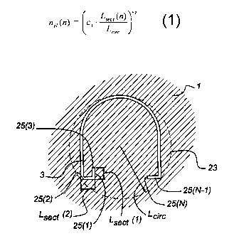
5 Figure 4a shows a cross section through the bearing 3 for the simple profile
of Figure 2.
The bearing 3 is surrounded by the (solid) material of the die 2. In many
occasions, the
data available from a CAD package is 2D data and comprises sections that may
be
straight or curved. These sections together define the die package. The curved
sections
may be parts of a circle. Figure 4a shows such sections 25(n), n = 1, 2, 3,
....., N. Each
10 of the sections have a section length LS~~(n), the value of which may
differ per section.
Of course, instead of 2D CAD data, 3D CAD data may be used if available.
In a first step, each of the sections 25(n) are divided into several line
elements 15
connected to one another via nodes 17 (figure 3a). After that, these sections
can be
directly used as starting contours in the meshing algorithm running on a
computer
arrangement. Figure 5 shows an example of a computer arrangement 27 that can
be
used for all calculating purposes.
The computer arrangement 27 comprises a processor 29 connected to a monitor
31, a
printer 33, data carrier I/O means 35 (I/O = input/output), I/O means 41, ROM
(read
only memory) 43, EEPROM (electrically erasable read only memory) 45, RAM
(random access memory) 47, a keyboard 49, and a mouse 51. Other components may
be connected to the processor 29 as well, as is known to persons skilled in
the art.
The data Garner I/O means 35 are arranged for receiving a data carrier, e.g.,
a floppy
disk 37, a CDROM 39, etc., and for reading data from and possibly writing data
to the
data carrier, as instructed by the processor 29.
The I/O means 41 are arranged as intermediary between the processor 29 and a
communication network 51 that may, e.g., be the PSTN (public switched
telephone
network) or the Internet.
CA 02395809 2002-06-26
WO 01/48699 PCT/NL99/00808
11
The processor 29 is drawn as one single block. However, it may be implemented
as
several parallel operating processors for performing several sub-tasks in
parallel which,
by the way, would enhance calculation speed significantly. Moreover, the
processor (or
some of the sub-processors) may be physically located elsewhere. The single
block 29
is only intended to indicate that there must be provided some intelligence
somewhere to
carry out predetermined calculation tasks. It may be implemented in any way
known to
persons skilled in the art.
Also the memory blocks 43, 45, 47 need not be restricted to those shown in
figure 5.
There may be more memories for storing databases, etc. They may also be
located
remotely from the arrangement shown.
Figure 4a shows a circle 23 having a diameter with length L~;,~ just large
enough to
entirely enclose the outer contour of the bearing 3. Each of the sections
25(n) is divided
into a number of line elements 15. The number of line elements n~;,(n) for
line section
25(n) is computed in accordance with the following equation:
Lsec t (n) c2 ( 1 )
= c~ .
Lcirc
where c, and c2 are constants with predetermined values. Preferably, c, is
between 10
and 200 and c2 is between 0.5 and 1Ø For example, c, = 50 and c2 = 0.75.
Moreover,
nei >_ 1, and if ne, as calculated by equation (1) is not an integer value it
is made equal to
the next higher integer value. By applying equation ( 1 ) and these further
rules, the
number of line elements 15 per section is known and the nodes 17 can be
located on the
sections 25(n).
As will be explained in detail below, the meshing generator as running on the
computer
arrangement of figure 5 (the program being for instance stored in EEPROM 45),
calculates meshes for the entire system including the extrusion tool
components and the
aluminum starting with these line elements 15 as input.
CA 02395809 2002-06-26
WO 01/48699 PCT/NL99/00808
12
The steps to be carried out by the mesh generator will be briefly explained
with
reference to Figure 6. Figure 6 shows, as an example, three coaxial tubes 53,
S5, 57.
Tubes 53, 55, and 57 correspond to the bearing, the pocket and the billet,
respectively,
assuming circular cross sections for simplicity, here.
The first tube 53 has a front cross-sectional surface 59 enclosed by an outer
contour 71.
The second tube 55 has a front cross-sectional surface 61 with an outer
contour 73 and
an inner contour 71'. The inner contour 71' is a projection of contour 71 of
front surface
59 of tube 53 on the plane in which contour 73 is located.
The third tube 57 has a front cross-sectional surface 63 with an outer contour
75 and an
inner contour 73'. The inner contour 73' is a projection of contour 73 of
front surface 61
of second tube 55 on the plane in which contour 75 is located.
The first, second and third tubes 53, 55, and 57 have respective rear surfaces
59"', 61",
and 63' all located in the same plane which is determined by the rear surface
of the third
tube 57. The rear surface of the third tube 57 is defined by an outer contour
75' and
inner contour 73". The inner contour 73" is a projection of contour 73 of
front surface
61 of second tube 55 on the plane in which contour 75' is located.
The tube 53 has envelop surfaces 65, 65' (within tube 55), and 65" (within
tube 57).
The height of tube 53 is hl + h2 + h3.
The tube 55 has envelop surfaces 67 and 6T (within tube 57). The height of
tube 55 is
h2 + h3.
The tube 57 has an envelop surface 69. The height of tube 57 is h3.
For purposes of the mesh generation, a projection surface 61' of surface 61 on
the plane
in which the front surface 63 of the third tube 57 is located, as well as
projection
contours 71" and 71"', respectively, of the outer contour 71 of front surface
59 of the
first tube 53 are defined. Projection contour 71" is located in the plane in
which the
CA 02395809 2002-06-26
WO 01/48699 PCT/NL99/00808
13
front surface of tube 57 is located. Projection contour 71"' is located in the
plane in
which the rear surface of tube 57 is located.
In most situations, contours 71, 73, and 75 will not be circularly shaped but
will be
determined by the cross section contours of the extrusion tool components.
Basically, the steps of the mesh generator to calculate the meshes for the
entire
structure can now be summarized as follows:
(a) generate a cross-sectional surface mesh for cross-sectional surface 59
starting
from contour 71 with line elements on contour 71 as determined with
equation ( 1 );
(b) copy mesh from step (a) to cross-sectional surfaces 59', 59", and 59"';
(c) generate envelop surface meshes for envelop surface 65, as well as for the
envelop surfaces 65' and 65" of the extensions, respectively, of tube 53
within
tubes 55 and 57, respectively; after step (c), the meshes of cross-sectional
surfaces 59, 59', 59", 59"', and envelop surfaces 65, 65', and 65" need to be
conform; i.e., nodes located on the boundaries between the envelop surfaces
65, 65', 65" and cross-sectional surfaces 59, 59', 59", and 59"' coincide for
the
respective envelop surface meshes and cross-sectional surface meshes;
(d) generate a volume mesh for tube 53 using the cross-sectional surface
meshes
of cross-sectional surfaces 59, 59', 59", and 59"' and the envelop surface
meshes of envelop surfaces 65, 65', and 65"; the volume mesh generated need
to be conform with these cross-sectional surface meshes, as well as with these
envelop surface meshes, i.e., nodes on the interfaces between this volume and
these surfaces must coincide for all generated meshes;
(e) repeat steps (a) through (d) for tube 55 and its extension in tube 57;
nodes at
the interface of the volume already meshed in steps (a) through (d) and the
volume meshed in the present step, i.e. at the envelop surfaces 65' and 65",
must coincide for both volumes adjacent to this interface surface;
(f) repeat steps (a) through (d) for tube 57; nodes at the interface of the
volume
already meshed in step (e) and the volume meshed in this step, i.e. at the
envelop surface 67', must coincide for both volumes adjacent to this interface
surface.
CA 02395809 2002-06-26
WO 01/48699 PCT/NL99/00808
14
It is to be understood that Figure 6 only shows the basic principles of
generating the
required mesh structure. Actually, there will be an aluminum (or other)
profile 13
extending from the bearing 3, a die 2 surrounding the bearing 3 and the pocket
5, the
container 8 surrounding the billet 7, and a ram 9 at the rear side of the
billet 7 (Figure
1). These structures will have to be added to the structure shown in Figure 1.
However,
the same principles are followed: i.e. front and rear cross-sectional surface
meshes,
envelop meshes and volume meshes are generated in essentially the same way. If
necessary, for instance for surfaces not being parallel to the extrusion
direction P,
corrections can be made as will be explained later. Again, a requirement is
that nodes
of meshes located on interface surfaces between different volumes are common
to the
volume meshes at opposing sides of the interface surfaces.
In the next paragraphs, it will be explained in detail how the mesh generator
operates in
accordance with these principles for the example of the aluminum profile
already
shown in cross-section in Figures 2, 4a and 4b.
As shown in Figure 7, the contours related to physical boundaries, such as the
bearing
opening, will be referred to as permanent boundaries 77 (Blacker and
Stephenson,
1991 ). The permanent boundaries remain constant during mesh generation. The
boundary between the ungridded domain and the gridded domain will be referred
to as
the current boundary 79. The current boundary 79 continuously evolves during
mesh
generation and eventually vanishes when the entire domain has been meshed.
For every node i on the permanent boundary 77 the starting thickness of the
layers t° is
prescribed. Also a growth factor f,. is specified for every node (see Figure
8). This
growth factor indicates the ratio between the thickness t;" of a layer n and
the thickness
t;"-' of the previous layer n - 1:
t~,t - f, _ t"-~ (2)
CA 02395809 2002-06-26
WO 01/48699 PCT/NL99/00808
1$
A directional refinement can then be achieved by setting the thickness in each
node to a
fraction of the length of the boundary line elements it is connected to. If
this fraction is
small, elements with a high aspect ratio will result.
1.2 Generating triangles with the current boundary nodes
Before adding nodal points to pave a subsequent layer 21 of elements a check
is made
to ensure that there is enough space between opposing parts of the current
boundary 79
to add a new layer 21 of elements. If there is not enough space, adding a
layer 21 would
imply the generation of overlapping elements. To avoid overlapping elements,
bridging
triangles are added at these locations. By adding these triangles the current
boundary 79
is altered such that no overlapping elements will be generated in a subsequent
paving
step. This approach ensures, as an added benefit, that no superfluous nodes 17
are
generated.
The generation of new triangles using the current boundary nodes 17 is
attempted by
checking all the line segments on this boundary. For a line segment e; spanned
by
nodes i and i + 1, triangles are generated by selecting as a third node j any
of the other
nodes 17 on the current boundary 79. The quality of all these triangles is
evaluated. A
triangle is considered to have an acceptable quality if all its corners are
sharp and the
distance h between the line segment e; and the node j satisfies:
n n
h ~ t; + t;+~ + t~ ~3)
2
Of all the triangles that are acceptable the aspect ratio, i.e. the longest
edge length of
the element divided by the shortest edge length, is assessed. The triangle
with the
lowest aspect ratio is then generated and the current boundary 79 is updated.
This
process is repeated until no more acceptable triangles can be generated.
1.3 Adding a layer of elements
CA 02395809 2002-06-26
WO 01/48699 PCT/NL99/00808
16
In order to continue the meshing procedure, new nodes 17 have to be generated.
These
new nodes 17 are positioned at a distance t" along the normals associated with
the
existing nodes 17 on the current boundary 79. The normal in a node 17 is
defined to be
the average normal of the line segments connected to that node 17. Between the
existing and the new nodes 17 quadrilaterals elements are constructed, which
are
subsequently divided into two triangles each (Figure 7).
A slightly different procedure must be followed at sharp angles in the current
boundary
79 in order to avoid distorted elements. Let a; denote the angle between the
normals
n;-, and n; which belong to the line elements e;_i and e;, respectively (see
Figures 9a
and 9b). For a; > ~r / 3 the two new quads that share node i would become too
distorted in node i. To prevent this, additional nodes are inserted (nodes j'
and j" in
Figures 9a and 9b). The number of additional nodes is given by m = a; = ~ / 3
. This
definition of m leads to a small number of extra nodes while maintaining an
acceptable
element shape. Generating elements using the additional nodes is
straightforward.
1.4 Merging nodes on the current boundary
To keep the mesh as efficient as possible the number of nodes 17 on the newly
created
boundary is reduced to a minimum by merging nodes 17 that are almost
coincident.
Two nodes 17 are merged if the distance between the nodes 17 is less than the
average
layer thickness defined in these nodes 17. The replacing node 17 is positioned
exactly
between the two original nodes 17. Both the thickness and the growth factor in
the new
node 17 are the average of the values in the nodes 17 it replaces.
1.5 Smoothing the mesh
After the entire domain has been gridded the quality of the mesh is improved
by
flipping and subsequent node shifting. Flipping is used to replace elements
with large
angles. To obtain a balance between meshing ei~ort and mesh quality it is only
performed on elements that contain a corner with an internal angle greater
than 0.67.
The process of element flipping consists of joining a triangle with that
neighbouring
CA 02395809 2002-06-26
WO 01/48699 PCT/NL99/00808
17
triangle that shares the longest edge with the triangle to be flipped. These
two triangles
then form a quad; the common edge of the triangles is one of the diagonals of
the quad.
Next, the quad is split along the other diagonal to render two new triangles.
Reference
is made to 10 which shows flipping of an element with a bad corner (shaded).
If flipping does not improve the mesh, an attempt is made to shift the node 17
of the
triangle in which the large angle occurs. The displacement of the node 17
should
neither change the refinement direction of the mesh nor turn elements inside
out.
Therefore, a node 17 is only shifted if the polygon formed by the elements
connected to
that node 17 is convex. The node 17 is then moved to the geometrical centre of
the
polygon, as depicted in Figure 11.
1.6 Resulting meshes
In Figure 12a through 12d the meshes for the bearing 3, the pocket 5, the
billet 7, and
the ram 9, respectively, resulting from the procedure introduced above have
been
depicted for the example configuration of Figure 2. It is observed that the
scale of the
billet 7 (Figure 12c) and the ram 9 (Figure 12d) differ from those of the
bearing 3
(Figure 12a) and the pocket 5(Figure 12b). The discretization of each contour
is
identical for every mesh it occurs in, i.e. nodes coincide there, which
facilitates the
meshing of the envelope surfaces. As can be seen, high aspect ratio triangles
have been
generated for the bearing to render many elements across the thickness of the
extrusion
profile because high gradients in the solution fields are to be expected
there. The mesh
of the ram surface is much coarser because near the ram 9 the gradients will
be very
low.
2 Meshing the surfaces - Expansion generator
The meshing of the envelope surfaces is performed in two steps. First, quads
(quadrilaterals) are generated from the line segments in the discretized cross-
section
contours. Next, these quads are subdivided into triangles. This method of
meshing
requires that the discretizations of the two contours that bound the envelope
are
identical.
CA 02395809 2002-06-26
WO 01/48699 PCT/NL99/00808
18
The quads are created by translating the line elements 15 by a prescribed
distance to
render a new discretized contour. The line elements 15 from the two contours
are
combined into quads, as shown in Figure 13). This is repeated until the entire
envelope
surface is meshed with quads. By varying the translation distance between each
contour, different levels of refinement can be obtained in the extrusion
direction P.
To obtain a triangular surface mesh the quads have to be split into triangles.
As
indicated in Figure 13 a quad can be split into two triangles in two different
ways,
depending on the choice of the orientation of the diagonal in the quad. Since,
as a result
of the rectangular shape of the quad, both orientations will render triangles
with the
same quality, either orientation is acceptable. The diagonals are therefore
oriented such
that their direction alternates for adjacent quads. This eliminates the mesh
orientation
that would result from setting all diagonals in the same direction.
In Figure 14 the envelope and the cross-section surface meshes generated for
the
example problem are plotted. Figure 14 shows the surface meshes for the
extrusion
profile 13, the bearing 3, the pocket 5 and the billet 7. In this figure the
alternating
orientation of the diagonals on the envelope surfaces can clearly be seen. It
can also be
observed that the mesh of the bearing envelope is more refined than the meshes
of the
extrusion profile and the pocket envelopes. This is done to appropriately
capture the
high gradients in the solution field in the bearing 3.
3 Meshing the volumes - Expansion generator
Of all the volumes that have to be filled with tetrahedral elements the
volumes of the
pocket 5, the bearing 3 and the extrusion profile 13 are discretized using the
expansion
mesh generator functions discussed in this section. The volumes of the billet
7 and the
die 2 are meshed using the generator functions discussed in the next section.
The
expansion generator applied in this work generates tetrahedra (below called
"tets") in
two steps which will be treated in more detail in the following. First, prisms
are created
from the triangles in the cross-section meshes. Next, the prisms are
subdivided into
tetrahedra. The volumes that can be meshed with this expansion generator are
restricted
CA 02395809 2002-06-26
WO 01/48699 PCT/NL99/00808
19
to volumes of which the top and the bottom surface have topologically
equivalent
meshes and of which the envelope surface has been created using the expansion
surface
generator dealt with in Section 2.
3.1 Generating prisms
The creation of the prisms is performed in a process similar to the creation
of the quads
in the envelope surfaces. Each triangle of the cross-section mesh is
translated in the
extrusion direction P to render a new cross-section mesh (see also Figure 15).
Subsequently, the triangles of both cross-section meshes are combined into
prisms. The
process of translating and combining is repeated until the entire volume is
filled. To
ensure that the nodes 17 on the contour of each cross-section coincide with
the nodes
17 of the envelope mesh that encloses the volume, the distances over which the
cross-section meshes are translated, are equal to the translation distances
that have been
used in the generation of the envelope mesh.
4.3.2 Generating tetrahedra
After the prisms have been generated they are split into tetrahedra. To do so,
each
rectangular face of a prism has to be split into two triangles. Reference is
made to
Figure 16 which shows splitting of a prism into 8 or 3 tetrahedra. The split
has to be
performed such, that the diagonals introduced on the rectangular faces of two
adjacent
prisms have matching directions. This will be referred to as the matching-
criterion.
With the diagonals set, each prism can be subdivided into tets using one of
two
paradigms. The first consists of introducing a node 17 in the baricenter of
the prism.
This node 17 then serves as the common top node 17 which, when combined with
each
of the 8 triangles on the sides of the prism, generates 8 tets. The second
method entails
the splitting of the prisms into 3 tets, without introducing an internal node
17 in each
prism. The second method is applied in this work because it reduces the number
of
nodes 17 and elements. Furthermore, it can easily be verified that the worst
aspect ratio
of the elements that are created by applying the 3-tet split is always better
than the
worst aspect ratio of the elements that are obtained with the 8-tet split.
CA 02395809 2002-06-26
WO 01/48699 PCT/NL99/00808
A disadvantage of the 3-tet split is that it imposes an extra requirement on
the
orientation of the diagonals of each prism. The orientation of the diagonals
should not
only match for adjacent prisms, but within one prism the diagonals should be
oriented
5 such that the 3-tet split is possible (Lohner, 1993). The 3-tet criterion
dictates that both
orientations of the diagonals should occur on the rectangular faces of an
individual
prism: see also Figure 17 which shows a diagonal orientation with respect to
the 3-tet
criterion.
10 An iterative procedure is used to select the orientation of the diagonals
in a pattern that
meets the additional 3-tet requirement (Van Rens et al., 1998c). With the
predefined
diagonal orientations of the faces in the envelope mesh as a starting point a
loop over
the prisms is performed. For those prisms in which the orientation of the
diagonal has
been set for one or two rectangular faces, the orientation is set for one
additional face.
15 The orientation is chosen such that the diagonals of both this prism and of
the adjacent
prism obey the matching criterion and do not violate the 3-tet criterion.
However, it is
not possible to satisfy the matching criterion and the 3-tet criterion for
both prisms in
case both prisms already have two diagonals set and the 3-tet criterion in
each prism
requires non-matching diagonal orientations on their mutual face. In this case
the
20 orientation of the diagonal is set such that the current prism meets the 3-
tet criterion,
which implies that the adjacent prism obtains a diagonal configuration that
does not
satisfy the 3-tet criterion. The prisms with incorrect diagonal configurations
are dealt
with next. This loop is repeated until the diagonals of all the faces are set.
Due to the possible incompatibility between the matching and the 3-tet
criterion
described above, it is likely that the mesh contains prisms for which the 3-
tet criterion
is not satisfied. The orientation of the diagonals in these prisms is
corrected as follows.
For each prism that violates the 3-tet criterion the orientation of one of the
diagonals is
changed while the diagonal of the adjacent prism is altered accordingly to
ensure that
the matching criterion is not violated. Of the three rectangular faces in the
incorrect
prism on which the diagonal can be swapped that face is selected for which the
adjacent
prism still conforms to the 3-tet criterion after the swapping. If none of the
adjacent
prisms allow the swapping of a diagonal, the diagonal direction of one face is
altered
CA 02395809 2002-06-26
WO 01/48699 PCT/NL99/00808
21
nevertheless, thus causing the 3-tet criterion to be violated in the prism
adjacent to this
face. Consequently, it is possible that after the alteration of the diagonal
directions
other prisms violate the 3-tet criterion. These prisms are identified by
performing a new
scan for incorrect prisms, which are adjusted in turn. This is repeated until
all prisms
satisfy the 3-tet criterion (typically 1 to 2 iterations are required). To
avoid repetitions,
the orientation of each diagonal can be altered only once in this process.
4 Meshing the volumes - Unstructured generator
The tetrahedral mesh of the billet 7 (or the die package) cannot be generated
using the
expansion generator discussed in Section 3 because this generator requires
that the
volume has topologically equivalent cross-section meshes on both ends of an
envelope
mesh. The mesh of the ram surface is much coarser than that of the combined
bearing,
pocket and billet surface. Therefore, an unstructured mesh generator is used
to generate
the tetrahedral mesh of the billet 7 (the die package is considered separately
in Section
7).
It is beyond the scope of this document to give a detailed description of the
unstructured mesh generator and therefore only the basic ideas are presented
here. The
unstructured mesh generator is based on ideas similar to the paving approach
introduced in Section 1. It consists of the following steps:
(a) Process the input data
Repeat
(b) Generate tetrahedra using existing nodes 17 on the current boundary 79
(c) Try to add one new node 17 to generate one new tetrahedron
- on success goto (b), else goto (d)
(d) Apply Delaunay method to resolve complex areas
(f) Smooth the mesh
(g) Delete elements with unacceptable shape or size
(h) Until entire domain is meshed
The concepts behind each of the steps will be discussed briefly.
CA 02395809 2002-06-26
WO 01/48699 PCT/NL99/00808
22
4.1 Input data
The input consists of the triangulation data for the volume boundary. As in
the paving
algorithm a distinction is made between the permanent, physical boundary and
the
current, constantly evolving boundary. Before elements have been generated the
permanent and the current boundary 79 coincide. While elements are generated
the
current boundary 79 changes and eventually vanishes.
The triangulation of the permanent boundary 77 is used to compute the edge
length
distribution of the boundary mesh. The edge lengths on the boundary are
interpolated
inside the volume to obtain a field of desired edge lengths for the entire
domain. This
field of edge lengths is used to determine the coarseness of the mesh
everywhere in the
domain.
4.2 Generate elements with the current boundary nodes
Before adding new nodes 17 a check is made whether elements can be generated
using
the existing nodes 17 on the current boundary 79. This is done by considering
all
triangles on the current boundary 79. For each triangle, tets are generated by
combining
the triangle with all the other nodes 17 on the current boundary 79. For each
tet, the
lengths of the edges that connect the node 17 to the triangle are computed.
Also, the
angles between these edges and the triangle surface are determined. The edge
lengths
and angles are compared for every tet associated with one triangle. If at
least one tet has
edge lengths and angles that are acceptable the tet that is most resembling to
an
equilateral tet is generated. To determine whether the edge lengths of a new
tet are
acceptable, they are compared to the local desired edge length that is stored
in the field
computed in step (a), Section 4.1. The angles of a tet are acceptable if they
are within
preset limits. After a tet is generated the current boundary 79 is updated.
Then the loop
over the current boundary 79 is repeated until no additional tets can be
generated.
4.3 Adding a node to generate a tetrahedron
CA 02395809 2002-06-26
WO 01/48699 PCT/NL99/00808
23
If no more tets can be created from the current boundary 79 mesh a new node
has to be
generated to continue the meshing procedure. The new node 17 is created using
a
triangle in the current boundary 79 as basis (see also Figure 18) and is
positioned along
the normal of the triangle that starts in the geometrical centre of the
triangle. The
position is selected such that the edges of the new tet between the triangle
and the new
node 17 have the desired length. If the new node 17 is positioned inside the
unmeshed
part of the domain, the node 17 and the tet are maintained and the current
boundary 79
is updated. Then step (b) is repeated to generate elements with the updated
current
boundary 79. If the new node 17 is positioned inside an existing tet, the node
17 and the
tet are discarded and the next triangle is used to create a new tet by adding
a node 17.
Ibis is repeated until a node 17 and tet have been generated or all triangles
have been
considered. If all the triangles have been tried and no new nodes 17 could be
generated
the current boundary 79 will be very complex. In this case a Delaunay mesh
generator
will be employed for the remaining unmeshed domain.
4.4 Applying the Delaunay algorithm
The Delaunay algorithm is used to deal with complex current boundaries. For a
detailed
description of the Delaunay method the interested reader is referred to (Zheng
et al.,
1996) or (Joe, 199 1991 ) and references therein. Here it is only mentioned
that the
Delaunay method is capable of generating a tetrahedral mesh for almost any
boundary
triangulation without introducing additional nodes 17. One of the few cases
for which it
fails, is a boundary that is topologically equivalent to a prism with
incorrect boundary
orientations as depicted in Figure 17. Then an additional node 17 has to be
added to
generate 8 tets. The major drawback of Delaunay's method is that it often
generates
elements with very poor aspect ratios. Therefore it is only used if the
element
generation algorithms in steps (b) and (c) have failed.
The current boundary 79 is not used for the Delaunay algorithm because the
region it
encloses can be very slender, which may result in extremely deformed tets.
Therefore
the current boundary 79 is redefined by eliminating all the elements connected
to nodes
17 on the current boundary 79 (see also Figure 19 which shows removing of
current
boundaries). After the element elimination the nodes 17 that were on the
current
CA 02395809 2002-06-26
WO 01/48699 PCT/NL99/00808
24
boundary 79 are no longer connected to any elements and are therefore deleted
as well.
Next, the Delaunay algorithm is applied to the redefined boundary.
4.5 Smoothing the mesh
The mesh is smoothed to increase the quality of the tets. This smoothing is
performed
using a standard Lagrangian smoothing algorithm. This algorithm consists of a
loop
over all nodes 17 in the mesh. For each node 17 the polyhedron that is spanned
by the
elements connected to the node 17 is constructed. Then the node 17 is
translated to the
geometrical centre of that polyhedron. It should be noted that it is possible
that
elements become overlapping during this rather crude smoothing method. If this
happens the inside-out elements are dealt with in the next step.
4.6 Deleting unacceptable elements
At the end of one meshing iteration two types of unacceptable elements can
occur in
the mesh. The first type of unacceptable elements are those elements that
overlap other
elements as a result of the node 17 repositioning during the smoothing of the
mesh.
Such elements are never acceptable and are all marked for deletion. The second
type of
unacceptable elements are those elements which have edge lengths that deviate
too
much from the locally desired edge length. Of all the elements that have
unsuitable
edge lengths only the worst element is marked for deletion.
The marked elements are deleted along with all the elements that share a node
17 with
the marked elements. Since the nodes 17 of the marked elements are not
connected to
any elements anymore after the element deletion, these are deleted as well.
The deletion
of marked elements causes the reformation of a current boundary 79 which
necessitates
another meshing iteration. The mesh generation is terminated if no more
elements have
been marked for deletion.
4.7 Resulting mesh of the die package
CA 02395809 2002-06-26
WO 01/48699 PCT/NL99/00808
The mesh of the die package depicted in Figure 20a has been generated using
the un-
structured mesh generator. An intersection of the die package is plotted in
Figure 20b.
In the intersection plane of the die 2 the pocket 5, the bearing 3 and the
outflow offset
85 can be identified. The outflow offset 85 ensures that the aluminum of an
unbalanced
5 profile does not touch the die 2 when the profile exits the die 2 under an
angle.
The domain of the die 2 and the backer 87 are meshed separately. At the
aluminum-die
interface the surface mesh of the die domain is taken in conformity with the
mesh of
the aluminum surface to simplify the modelling of the interactions between
these
10 domains. Also, the surface mesh of the backer at the die-backer interface
is identical to
the surface mesh of the die 2 to simplify the discretization of the Lagrange
multiplier
that is used to model the frictionless contact between the die 2 and the
backer 87. Since
the gradients in the displacement field will be larger in the die domain than
in the
backer domain the element size in the die domain is smaller than in the backer
domain.
5 Stretching the bearing
In the example mesh generated in the previous sections the bearing 3 has a
constant
length in extrusion direction. However, in reality the bearing length varies
along the
bearing contour and numerical experiments indicate that the length of the
bearing 3 has
a significant influence on the outcome of the simulations (Van Rens et al.,
1998d).
Therefore, the constant bearing length mesh is adapted in a number of steps to
incorporate the varying bearing length (Van Rens et al., 1998e). These steps
are
visualised in Figures 21a through 21f, but only for the bearing volume mesh.
Of course,
these operations are applied to the outflow volume mesh and the die mesh as
well to
ensure the meshes remain compatible. In each of the steps nodes 17 are
translated in the
extrusion direction while the topology of the mesh remains the same. This
implies that
different bearing lengths can be studied by repeating only the stretching
operation, i.e.
without having to generate a new mesh.
The mesh of the aluminum bearing volume with a constant bearing length, as
depicted
in Figure 21a, serves as a point of departure. The length of the bearing 3 is
only
specified in a discrete number of control nodes 17 along the bearing contour
and varies
CA 02395809 2002-06-26
WO 01/48699 PCT/NL99/00808
26
linearly between these nodes 17. In the first step the control nodes 17 are
translated to
the specified position, as shown in Figure 21b.
In the second step all the other nodes 17 on the contour are translated to the
real bearing
geometry. The translation distance for these nodes 17 is computed by a linear
interpolation between the control nodes 17, as shown in Figure 21 c. The
linear
interpolation is performed by solving a diffusion problem on the line segments
that
constitute the contour of the bearing 3. In this diffusion problem the
translation
distances are computed by prescribing the bearing lengths in the control
points as
Dirichlet boundary conditions.
It can be seen in Figure 21c that the cross-section surface that separates the
aluminum
bearing volume from the outflow volume has become very distorted. Therefore,
in the
third step, this surface is smoothed by repositioning the nodes 17 that belong
to this
surface, as shown in Figure 21 d. Many methods exist to compute the distance
over
which the surface nodes 17 have to be translated (see e.g. (Tezduyar et al.,
1992) and
(Johnson and Tezduyar, 1994)). Here, it is obtained in the same manner as in
the
previous step, by solving a diffusion problem on the surface. In this problem
the
translation distances for the surface are computed, using Dirichlet boundary
conditions
to prescribe the previously computed translation distances on the bearing
contour.
Lastly, in the fourth step, the volume mesh of the bearing 3 is smoothed by
translating
the nodes 17 in this volume, as shown in Figure 21 e. Again, the translation
distances
for the nodes 17 in the volumes are obtained by solving a diffusion problem
for the
bearing volume. In this diffusion problem the previously computed translation
distances of the cross-section surface are imposed as Dirichlet boundary
conditions.
When both the bearing and the outflow meshes are plotted after the stretching,
Figure
21f is obtained that shows the final mesh including the extrusion profile.
4.6 Extension to hollow dies
For hollow profiles the shape of the aluminum domain is considerably more
complicated than for flat profiles. This is caused by the fact that the die is
constructed
CA 02395809 2002-06-26
WO 01/48699 PCT/NL99/00808
27
out of two parts, instead of one. This is shown in Figures 22a and 22 b. The
first part is
the die plate 2' which determines the external contour of the profile 13. In
the die plate
2' a welding chamber 89 is added to allow the aluminum flow, that has split to
pass
legs 91 of a second part, i.e. a bridge part 95, to weld together again before
entering the
pocket 5 of the die. The second part, the bridge part 95, consists of a core
93 that
determines the internal contour of the profile 13 and the legs 91 which
support the core
93.
The core 93 and the die plate 2' consist of surfaces that are either
perpendicular or
tangential to the extrusion direction. This implies that they can be meshed
with the
methods described earlier in this document. However, as can be seen in Figures
22a
and 22b, the complex geometry of the legs 91 cannot be described with just
perpendicular or tangential surfaces. Therefore, the meshing of the aluminum
domain
associated with hollow profiles is performed in several steps. See Figures 23a
through
23f which shows removing of elements in four steps:
(a) The aluminum geometry is constructed taking only the geometry of the core
93 into
account. The geometry of the legs 91 is described separately.
(b) The aluminum geometry is meshed, incorporating the geometry of the core 93
but
neglecting the geometry of the legs 91, using the methods discussed in the
previous
sections.
(c) The elements of which all nodes 17 are positioned inside the geometry of
the legs
91 are removed.
(d) After the removal of the elements a set of external faces has been
generated. These
newly formed external faces are connected to nodes 17 that are inside the legs
91.
These nodes 17 are translated onto the surface of the legs 91. During the
translation
the new positions of the nodes 17 are determined such that they do not cause
elements to become overlapping. The translation is followed by a local
smoothing
of the mesh around the translated nodes 17. To realise this, the elements that
are
connected to newly formed external faces are marked. The nodes 17 of these
elements that are not connected to external faces are repositioned to increase
the
quality of the elements.
CA 02395809 2002-06-26
WO 01/48699 PCT/NL99/00808
28
(e) It is possible that near sharp edges some elements intersect the legs 91,
even though
their nodes 17 are on or outside the boundary of the legs 91. Therefore, the
elements that have their geometrical centre inside the geometry of the legs 91
are
deleted. The number of elements deleted in this step is generally very small.
S (f) The translation of step (d) is repeated. In this case the newly formed
external faces
are connected to nodes 17 that are positioned on or outside the geometry of
the legs
and these nodes 17 have to be translated onto the surface of the legs as well.
In Figures 24a and 24b an example is given of an initial and final mesh
belonging to the
aluminum domain of a rectangular hollow profile.
Above, the principles of generating meshes of simple and complex profiles has
been
explained with reference to an extrusion process. However, the mesn generator
described can be used in any other method for simulating physical behaviour of
an
object by means of a finite element analysis.
CA 02395809 2002-06-26
WO 01/48699 PCT/NL99/00808
29
List of publications:
T.D. Blacker and M.B. Stephenson. Paving: A new approach to automated
quadrilateral
mesh generation. Int. J. Numer. Methods Engrg., 32:811-847, 1991
J.F. Gobeau, T. Coupez, B. Vergnes, and J.F.A. Agassant. Computation of
profile dies
for thermoplastic polymers using anisotropic meshing. In Simulation of
Materials
Processing: Theory, Methods and Applications, pages 59-66, 1995
B. Joe. Delaunay versus max-min solid angle triangulations for three-
dimensional mesh
generation. Int. J. Numer. Methods Engrg. , 31:987-997, 1991
A.A. Johnson and T.E. Tezduyar. Mesh update strategies in parallel finite
element
computations of flow problems with moving boundaries and interfaces. Comput.
Methods Appl. Mech. Engrg., 119:73-94, 1994
R. Lohner. Matching semi-structured and unstructured grids for Navier-Stokes
calculations. In AIAA 93-3348-CP, pages 555-564, 1993
T.E. Tezduyar, M. Behr, S. Mittal, and J. Liou. A new strategy for finite
element
computations involving moving boundaries and interfaces. Comput. Methods Appl.
Mech. Engrg., 94: 353-371, 1992
B.J.E. van Rens, W.A.M. Brekelmans, and F.P.T. Baaijens. A semi-structured
mesh
generator applied to extrusion. In J. Huetink and F.T.P. Baaijens, editors,
Simulation of
Materials Processing: Theory, Methods and Applications, pages 621-626, 1998c
B.J.E. van Rens, W.A.M. Brekelmans, and F.P.T. Baaijens. Steady, three
dimensional
flow calculations of aluminum extrusion with complicated die geometries. In
J.L.
Chenot, J.F. Agassant, P. Montmitonnet, B. Vergnes, and N. Billon, editors,
Proceedings of the 1st ESAFORM conference on Material Forming, pages 495-498,
1998d
CA 02395809 2002-06-26
WO 01/48699 PCT/NL99/00808
B.J.E. van Rens, W.A.M. Brekelmans, and F.P.T. Baaijens. Three dimensional
finite
element analysis of aluminum extrusion. In B.H.V. Topping, editor, Advances in
Computational Mechanics with High Performance Computing, pages 25-32, 1998e
5 B.J.E. van Rens, D. Brokken, W.A.M. Brekelmans, and F.P.T. Baaijens. A two-
dimensional paving mesh generator for triangles with controllable aspect ratio
and
quadrilaterals with high quality. Engrg. with Computers, 14:248-259, 1998g
Y. Zheng, R.W. Lewis, and D.T. Gethin. Three-dimensional unstructured mesh
10 generation: Part 1. Fundamental aspects of triangulation and point
creation. Comput.
Methods Appl. Mech. Engrg., 134:249-268, 1996